US1852694A - Rail bonding - Google Patents
Rail bonding Download PDFInfo
- Publication number
- US1852694A US1852694A US71378A US7137825A US1852694A US 1852694 A US1852694 A US 1852694A US 71378 A US71378 A US 71378A US 7137825 A US7137825 A US 7137825A US 1852694 A US1852694 A US 1852694A
- Authority
- US
- United States
- Prior art keywords
- terminal
- rail
- bond
- copper
- strands
- Prior art date
- Legal status (The legal status is an assumption and is not a legal conclusion. Google has not performed a legal analysis and makes no representation as to the accuracy of the status listed.)
- Expired - Lifetime
Links
- 229910052802 copper Inorganic materials 0.000 description 30
- 239000010949 copper Substances 0.000 description 30
- RYGMFSIKBFXOCR-UHFFFAOYSA-N Copper Chemical compound [Cu] RYGMFSIKBFXOCR-UHFFFAOYSA-N 0.000 description 29
- 239000004020 conductor Substances 0.000 description 23
- 229910000831 Steel Inorganic materials 0.000 description 15
- 239000010959 steel Substances 0.000 description 15
- 239000002184 metal Substances 0.000 description 14
- 229910052751 metal Inorganic materials 0.000 description 14
- 238000003466 welding Methods 0.000 description 13
- 238000000034 method Methods 0.000 description 10
- 238000003475 lamination Methods 0.000 description 6
- 238000010276 construction Methods 0.000 description 4
- 238000004519 manufacturing process Methods 0.000 description 4
- OKTJSMMVPCPJKN-UHFFFAOYSA-N Carbon Chemical compound [C] OKTJSMMVPCPJKN-UHFFFAOYSA-N 0.000 description 2
- 229910052799 carbon Inorganic materials 0.000 description 2
- 238000005520 cutting process Methods 0.000 description 2
- 238000010891 electric arc Methods 0.000 description 2
- 235000013382 Morus laevigata Nutrition 0.000 description 1
- 244000278455 Morus laevigata Species 0.000 description 1
- 230000001154 acute effect Effects 0.000 description 1
- 230000003190 augmentative effect Effects 0.000 description 1
- 238000005452 bending Methods 0.000 description 1
- 238000005242 forging Methods 0.000 description 1
- 238000002844 melting Methods 0.000 description 1
- 230000008018 melting Effects 0.000 description 1
- 230000000630 rising effect Effects 0.000 description 1
- 238000010008 shearing Methods 0.000 description 1
- 230000035939 shock Effects 0.000 description 1
- 239000007787 solid Substances 0.000 description 1
Images

Classifications
-
- B—PERFORMING OPERATIONS; TRANSPORTING
- B60—VEHICLES IN GENERAL
- B60M—POWER SUPPLY LINES, AND DEVICES ALONG RAILS, FOR ELECTRICALLY- PROPELLED VEHICLES
- B60M5/00—Arrangements along running rails or at joints thereof for current conduction or insulation, e.g. safety devices for reducing earth currents
-
- Y—GENERAL TAGGING OF NEW TECHNOLOGICAL DEVELOPMENTS; GENERAL TAGGING OF CROSS-SECTIONAL TECHNOLOGIES SPANNING OVER SEVERAL SECTIONS OF THE IPC; TECHNICAL SUBJECTS COVERED BY FORMER USPC CROSS-REFERENCE ART COLLECTIONS [XRACs] AND DIGESTS
- Y10—TECHNICAL SUBJECTS COVERED BY FORMER USPC
- Y10T—TECHNICAL SUBJECTS COVERED BY FORMER US CLASSIFICATION
- Y10T29/00—Metal working
- Y10T29/49—Method of mechanical manufacture
- Y10T29/49826—Assembling or joining
- Y10T29/49908—Joining by deforming
- Y10T29/49925—Inward deformation of aperture or hollow body wall
- Y10T29/49927—Hollow body is axially joined cup or tube
- Y10T29/49929—Joined to rod
- Y10T29/49931—Joined to overlapping ends of plural rods
Definitions
- the arc has a tendency to center on the hottest part of the work and since steel is of relatively slow'heat conductivity, the surface of the rail attains a high temperature instantly and so attracts the arc, while on the other hand, the copper of the bond is relatively cold and slower to attract such are. It is consequently diflicult to run a V-seam between a copper and a steel body, as for example the terminal of a copper bond and a steel rail, with a copper pencil, i. e. to lay a string of metal in the angle between two such surfaces lying at approximately right angles to each other where the one surface is steel and the other is copper.
- the arc flame will center on the steel andhot drops of copper will fall on the copper surface and chill without welding; while if the surfaces be reversed in position, the molten copper will weld to the steel but will be chilled against the vertical copper surface, unless this surface be but an edge of such thinness that the heat of the adjacent are flame, together with that of the molten copper which falls in drops, is suflicient to produce the weld.
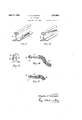
- FIG. 1 is a plan view of one form of myimproved rail bond terminal at an intermediate stage in its manufacture
- Fig. 2 is a similar view of such terminal as completed
- Figs. 3 and 4 are transverse sections of such completed terminal, the latter figure being somewhat conventionalized for clarity, the planes of the sections being indicated by the lines 3-3 and 4-4, respectively, Fig. 2
- Fig. 5 is a view. similar to that of Fig. 2 but showing a modified form of terminal
- Fig. 6 is a side elevational view of such modified form, as viewed from above in Fig. 5
- Fig. 7 is a trans-v verse section and Fig.
- Fig. 8 a longitudinal section of such modified form, the planes of the sections being indicated by the lines 77 and 88, Fig. 5;
- Fig. 9 is a front elevation of a diiferent type of bond showing another form of terminal;
- Fig. 10 is a transverse section of such terminal, the plane of the section being indicated by the line 10-10,
- Fig. 9 Figs. 11, 12 and 13 are diagrammatic perspective views illustrating the. method of application to the rail of bonds havin terminals of the three difl'erent modified orms still illustrated in Figs. 2, 5 and 9, respectively; and
- Figs. 14 and 15 are side elevations of a bond of yet another type with two differently modified forms of terminal embodying my present improved construction.
- the bond there illustrated is of the general type in which the conductor body 1 is formed from a stranded cable.
- the terminal 2 which is designed to be welded to the rail, is formed by first sheathing the corresponding end of such cable in a thin sheet 3 of copper in order to give form to such terminal and strength against vibration and shock when the bond is welded to the rail.
- the terminal including such sheath or sleeve 3 and the portions of the strands of.
- the body that enter therein is then flattened by means of a suitable die under a hammer or press so that such strand portions are left in tightly compressed condition, as shown in Figs. 3 and 4.
- the flattening of the terminal is graduated at its inner end, as shown in Figs. 1 and 2, the sleeve 3 being left in its original approximately circular form at such end so that the entering strands may havea slight amount of relative movement at the point in question.
- the bond is finished by shearing the terminal 2 on a line such as the line a-a, Fig. 1, at an angle to the median line of the terminal and preferably also at an angle to the plane of such terminal.
- a line such as the line a-a, Fig. 1
- the end of the strands of the conductor body that enter into the terminal are of course individually sheared at a corresponding angle and so present for welding an increased area of contact over that presented by a normal section of the flattened terminal.
- the amount of increase in such area of contact may be correspondingly varied, the preferred angle being the one that will give the prescribed ratio of contact weld between the coyiper of the conductor and the steel of the m1
- the edge of the latter is formed into an acute angle bcd, as shown in Fig. l, thus presenting a more or less sharply defined edge upon which to play the are.
- Fig. 4 a portion of the exposed conductors has not been shown in end elevation in order that the angle of cut may be more clearly illustrated.
- the portion of the terminal adjacent the cut aa may be bodily bent out of the plane of the terminal so that when the terminal is laid on the fiat surface of a rail, the whole edge 5 will stand slightly above or clear from such surface (Fig. 5).
- This last mentioned form of terminal is further illustrated in Figs. 6, 7 and 8, which clearly illustrate the manner in which the terminal is twisted or formed in order thus to ofi'set the angularly cut welding edge of the terminal.
- Figs. 9 and 10 still another type of bond is shown, the body 10 whereof, although composed as before of stranded cable, is of U- shape. Such body is shown as comprising twin cables 11, but one or more may be employed as found desirable.
- the respective ends of the stranded conductor body enter in sleeves 12 which are flattened in order tightly to compress the strand portions in question.
- These terminals are thereupon cut at an angle ee (see Fig. 10) that serves to increase the area of contact over a normal section and, as before, the portion of the terminal adjacent such edge is bodily bent or twisted so as to offset such angularly inclined welding edge.
- the first of the foregoing types of bond shown in its finished form in Fig. 2 is designed for application to the top of the base of a rail either for bonding round joints, bonding special work or for cross bonding, and in Fig. 11 such bond is shown as thus attached to a rail R.
- the second type of bond shown in Figs. 5 and 6 is designed more especially for bonding against the vertical surface of a rail as on the head or web of a girder rail, one illustrative mode of application of such bond being shown in Fig. 12.
- the third type of bond shown in Fig. 9, like the preceding type, is designed for application laterally to the rail, one thereof being shown in Fig. 13.
- each of the three types of bond hereinbefore referred to is shown as composed of a stranded cable in which the strands particularly as they enter the flattened terminal lie approximately parallel with each other
- the improvement consisting in forming the welding edge of such terminal at an angle to the strands which thus enter therein, may also be advantageously used with the so-called laminated type of bond.
- the term strand may be understood as denoting either a cable strand, as found in such first three types of bond, or the lamination of such last mentioned type, or for that matter a lsjigle, solid strand or bar may compose the y of the bond.
- terminals 16 are 7 sheathed withthin sheets 17 of copper after the uncut superposed laminations.
- a point p of importance in regard to this detail is the fact that these superposed laminations so re- 7 tard the flow'of heat from one to another that there is never any danger of melting through even though the uppermost one, that is directly exposed to the arc and molten copper, may be melted.
- the form of the notch may be varied to give any desired ratio of contact area between conductor and rail, the exact form depending on the width of the lamination, capacity of bond and ratio of contact specified.
- the notch 20 may be a V notch, the sides of which meet each other, instead of a notch with a flat bottom, such as illustrated in Fig. 14.
- the bond but on the rail at the lowest point exposed within the space between the bond and rail.
- Copper is then added as the flame is continued, the molten metal first added settling and adhering to the very lowest part of the exposed rail surface and the space between the bond terminal and rail being thereupon built up by applying the flame to therail and adding copper.
- the ends of the space in question may be closed or dammed in the same fashion as the bottom of such space. reaches the lower edge of the inclined or angularlycut extremity of the terminal, the latter is easily united to the rising column of hot metal as is also the whole of such inclined or diagonally cut extremity.
- such terminal where constructed in the manner hereinbefore set forth avoids the well known characteristic of flame weld type bonds as heretofore utilized, viz., that of giving the rail contact only along'the line at the top of the weld.
- a rail bond having a stranded metallic conductor body, and an elongated flattened terminal wherein the strands of said body enter in tightly compressed deformed and approximately parallel relation, such flattened terminal with included strands being cut off at an angle, the plane of said out being inclined to the median line, parallel to the longest side of said flattened terminal, at other than a right angle, and the plane of said out being also inclined to a plane perpendicular to the plane of such terminal so as correspondingly to increase the area of the exposed ends of such strands, the thickness of said terminal being less than that of said conductor body.
- a method of forming a terminal on a rail bond having a stranded metallic conductor body which comprises surrounding the end of the body with a metal sheath, flattening the sheath and compressing and flattening the portions of the strands therein, then cutting such terminal at an angle to the median line thereof whereby the area of the exposed ends of such strands is correspondingly increased.
- a method of forming-a terminal on a rail bond having a stranded metallic conductor body which comprises surrounding the end of the body with a metal sheath, flattening the sheath and compressing and flattening the portions of the strands therein, then cutting such terminal both at an angle to the median line and to the plane of the terminal whereby the area of the exposed ends of such strands is correspondingly increased.
Landscapes
- Engineering & Computer Science (AREA)
- Mechanical Engineering (AREA)
- Connections Effected By Soldering, Adhesion, Or Permanent Deformation (AREA)
Description
Ap 1932- c. A. CADWELL RAIL BONDING 2 Sheets-Sheet 1 Filed Nov. 25, 1925 INVENTOR.
C'ildif/ -17. CQQCUG/Z I 'maM ATTORNEYS.
April 5, 1932. c. A. CADWELL RAIL BONDING Filed Nov. 25, 1925 2 Sheets-Sheet 2 INVENTOR. (Earle: J7. ("aciweil ATTORNEYS Patented Apr. 5, 1932 ATE L OFFICE CHARLES A. cAnwELL, or cnnvnnam: HEIGHTS, OHIO, asslenon 'ro'rI-IE nnnczrnrc RAILWAY IMPROVEMENT comrm, or cnnvnnmn, 0310, A conromrrou or OHIO BAIL BONDING Application filed November 25, 1925. Serial No. $1,878.
The welding of copper to steel for the purpose of rail bonding was first done by the cast weld process in which superheated molten copper was poured into a mold against the surface of the rail and around the end of the copper conductor. Experience proved that only where the hot metal impinged upon the surface of the rail in such a manner as to break rather than merely deflect the stream,
would there be a weldin of the copper to the steel, this regardless o the temperature of the metal poured. Similarly, in arc welding where the molten metal is supplied from a copper electrode, and in fact 1n all metallic arc welding, the transfer of the molten drops of metal from the pencil to the work or weld must be made at the precise point to which the electric arc is sprung if a molecular weld of this drop to the work is to be had.
In the method of electric arc welding just referred to, the arc has a tendency to center on the hottest part of the work and since steel is of relatively slow'heat conductivity, the surface of the rail attains a high temperature instantly and so attracts the arc, while on the other hand, the copper of the bond is relatively cold and slower to attract such are. It is consequently diflicult to run a V-seam between a copper and a steel body, as for example the terminal of a copper bond and a steel rail, with a copper pencil, i. e. to lay a string of metal in the angle between two such surfaces lying at approximately right angles to each other where the one surface is steel and the other is copper. If the vertical surface be of steel and the horizontal one of copper, for instance, the arc flame will center on the steel andhot drops of copper will fall on the copper surface and chill without welding; while if the surfaces be reversed in position, the molten copper will weld to the steel but will be chilled against the vertical copper surface, unless this surface be but an edge of such thinness that the heat of the adjacent are flame, together with that of the molten copper which falls in drops, is suflicient to produce the weld.
The foregoing observations apply not only to the case where t e copper pencil consti tutes an electrode from which the arc is sprung, but also to the alternative procedure in WhlCh a carbon electrode is em loyed and the end of the copper pencil (not mcluded in the electric circuit) is gradually melted off I Such observation's 1i ewise apply to the method of weldby bein inserted in the arc.
in t e claims, the annexed drawings and'the following description settin forth in detail certain steps and means em 0d g the invention, such disclosed steps an means constituting, however, but several of the various ways in which the principle of the invention ma .be'used.
n said annexed drawings Fig. 1 is a plan view of one form of myimproved rail bond terminal at an intermediate stage in its manufacture; Fig. 2 is a similar view of such terminal as completed; Figs. 3 and 4 are transverse sections of such completed terminal, the latter figure being somewhat conventionalized for clarity, the planes of the sections being indicated by the lines 3-3 and 4-4, respectively, Fig. 2; Fig. 5 is a view. similar to that of Fig. 2 but showing a modified form of terminal; Fig. 6 is a side elevational view of such modified form, as viewed from above in Fig. 5; Fig. 7 is a trans-v verse section and Fig. 8 a longitudinal section of such modified form, the planes of the sections being indicated by the lines 77 and 88, Fig. 5; Fig. 9 is a front elevation of a diiferent type of bond showing another form of terminal; Fig. 10 is a transverse section of such terminal, the plane of the section being indicated by the line 10-10, Fig. 9 Figs. 11, 12 and 13 are diagrammatic perspective views illustrating the. method of application to the rail of bonds havin terminals of the three difl'erent modified orms still illustrated in Figs. 2, 5 and 9, respectively; and Figs. 14 and 15 are side elevations of a bond of yet another type with two differently modified forms of terminal embodying my present improved construction.
As hereinbefore indicated, in order to weld a copper conductor to the horizontal face of a steel rail by means of a copper are pencil, I have found that the face of the conductor terminal, which is presented for welding, had best be but an edge of such thinness that the heat of the adjacent arc flame which is sprung from the face of the steel, together with that of the molten copper which falls in drops, is sufficient to produce simultaneously Y with the weld of a drop to the steel a weld of that same drop of copper to the edge of the copper conductor. Only if such conditions obtain can a complete weld between every wire or lamination of the conductor and the weld metal be secured.
Referring to Figs. 1 to a, inclusive, the bond there illustrated is of the general type in which the conductor body 1 is formed from a stranded cable. The terminal 2, which is designed to be welded to the rail, is formed by first sheathing the corresponding end of such cable in a thin sheet 3 of copper in order to give form to such terminal and strength against vibration and shock when the bond is welded to the rail.
The terminal including such sheath or sleeve 3 and the portions of the strands of.
the body that enter therein, is then flattened by means of a suitable die under a hammer or press so that such strand portions are left in tightly compressed condition, as shown in Figs. 3 and 4. The flattening of the terminal is graduated at its inner end, as shown in Figs. 1 and 2, the sleeve 3 being left in its original approximately circular form at such end so that the entering strands may havea slight amount of relative movement at the point in question.
The bond is finished by shearing the terminal 2 on a line such as the line a-a, Fig. 1, at an angle to the median line of the terminal and preferably also at an angle to the plane of such terminal. As a result, the end of the strands of the conductor body that enter into the terminal are of course individually sheared at a corresponding angle and so present for welding an increased area of contact over that presented by a normal section of the flattened terminal. By varying the angle of inclination of the shear cut aa,
the amount of increase in such area of contact may be correspondingly varied, the preferred angle being the one that will give the prescribed ratio of contact weld between the coyiper of the conductor and the steel of the m1 At the same time that the area of contact of the individual strands is thus increased by inclining the cut at an angle to the plane of the terminal, the edge of the latter is formed into an acute angle bcd, as shown in Fig. l, thus presenting a more or less sharply defined edge upon which to play the are.
7 In Fig. 4 a portion of the exposed conductors has not been shown in end elevation in order that the angle of cut may be more clearly illustrated.
In order to render such edge still more effective, the portion of the terminal adjacent the cut aa may be bodily bent out of the plane of the terminal so that when the terminal is laid on the fiat surface of a rail, the whole edge 5 will stand slightly above or clear from such surface (Fig. 5). This last mentioned form of terminal is further illustrated in Figs. 6, 7 and 8, which clearly illustrate the manner in which the terminal is twisted or formed in order thus to ofi'set the angularly cut welding edge of the terminal.
In Figs. 9 and 10 still another type of bond is shown, the body 10 whereof, although composed as before of stranded cable, is of U- shape. Such body is shown as comprising twin cables 11, but one or more may be employed as found desirable. As before, the respective ends of the stranded conductor body enter in sleeves 12 which are flattened in order tightly to compress the strand portions in question. These terminals are thereupon cut at an angle ee (see Fig. 10) that serves to increase the area of contact over a normal section and, as before, the portion of the terminal adjacent such edge is bodily bent or twisted so as to offset such angularly inclined welding edge.
The first of the foregoing types of bond shown in its finished form in Fig. 2 is designed for application to the top of the base of a rail either for bonding round joints, bonding special work or for cross bonding, and in Fig. 11 such bond is shown as thus attached to a rail R. The second type of bond shown in Figs. 5 and 6 is designed more especially for bonding against the vertical surface of a rail as on the head or web of a girder rail, one illustrative mode of application of such bond being shown in Fig. 12. The third type of bond shown in Fig. 9, like the preceding type, is designed for application laterally to the rail, one thereof being shown in Fig. 13.
While the conductor body of each of the three types of bond hereinbefore referred to is shown as composed of a stranded cable in which the strands particularly as they enter the flattened terminal lie approximately parallel with each other, the improvement, consisting in forming the welding edge of such terminal at an angle to the strands which thus enter therein, may also be advantageously used with the so-called laminated type of bond. For the purpose of this specification, the term strand may be understood as denoting either a cable strand, as found in such first three types of bond, or the lamination of such last mentioned type, or for that matter a lsjigle, solid strand or bar may compose the y of the bond.
As is well known, in the manufacture of such laminated type of bond, a continuous strip of flat wire copper of prescribed width,
is wound and formed to present a body of general U form, as shown in Fig. 14, with oppositely directed terminals 16. In the present improved construction, such terminals are 7 sheathed withthin sheets 17 of copper after the uncut superposed laminations. A point p of importance in regard to this detail is the fact that these superposed laminations so re- 7 tard the flow'of heat from one to another that there is never any danger of melting through even though the uppermost one, that is directly exposed to the arc and molten copper, may be melted. Asthe arc pencil, centered on the steel, is moved toward the side of the notch, it readily brings the exposed cut ends of the laminations to a welding temperature, with the result that a perfect union is secured between everylamination and the metal of the weld as well as between the latter and the rail. As in the case of the angularly cut terminals of the stranded cable types of bond, so with such laminated bond, the form of the notch may be varied to give any desired ratio of contact area between conductor and rail, the exact form depending on the width of the lamination, capacity of bond and ratio of contact specified. Thus, for example, as shown in Fig. 15, the notch 20 may be a V notch, the sides of which meet each other, instead of a notch with a flat bottom, such as illustrated in Fig. 14.
V The increased effectiveness achieved by the use of my improved form of bond terminal in each of the several forms il- I lustrated is due to the fact that the sectional area of the portion, of the conductor body that enters into such terminal has been enlarged. The advantages flowing from this construction are particularly noticeable where the terminal requires to be welded against a limited portion of the rail face, as for example against the head as illustrated in Figs. 12 and 13. Such advantages, furthermore, may be augmented by the arrangement illustrated in Fig. 13, consisting in the utilization or provision of a dam 22, such as a suitably'shaped block of refractory non 5 conducting material, e. g. carbon, between the position on the rail, as shown, the flame for welding is directed not on. the bond but on the rail at the lowest point exposed within the space between the bond and rail. Copper is then added as the flame is continued, the molten metal first added settling and adhering to the very lowest part of the exposed rail surface and the space between the bond terminal and rail being thereupon built up by applying the flame to therail and adding copper. If found desirable, the ends of the space in question may be closed or dammed in the same fashion as the bottom of such space. reaches the lower edge of the inclined or angularlycut extremity of the terminal, the latter is easily united to the rising column of hot metal as is also the whole of such inclined or diagonally cut extremity.
Whatever may be the particular arrangement of terminal or method of application employed, such terminal where constructed in the manner hereinbefore set forth avoids the well known characteristic of flame weld type bonds as heretofore utilized, viz., that of giving the rail contact only along'the line at the top of the weld. In other words, as heretofore constructed and applied, in bonds of the type in question, at the best the crosssectional area of the conductor is brought abruptly into the weld metal of the terminal and is continued through this medium to the rail without enlargement to meet the lesser conductivity of the weld medium and especially that of the rail; while as a matted of fact, more frequently the effective cross-sectional area is reduced incidentally to the application of the bond to the rail, except where some special provision is made as by attaching to the end of the conductor a shelf to sup port additional molten metal (copper) and give the necessary contact area with the rail. In contradistinction to the foregoing, not only is my improved form of terminal much more, simple and less expensive to manufacture, but it provides an even more effective way to obtain the desired increase of contact area than where a special terminal is formed by upsetting or forging the end of the conductor, or by welding thereto a steel body as in prevailing commercial practice.
Other forms may be employed embodying the features of my invention instead of the one here explained, change being made in .the form or construction, provided the ele men'ts stated by any of the following claims or the equivalent of such stated elements be When the level of the molten metal employed, whether produced by my preferred method or by others embodying steps equivalent to those stated in the following claims.
pressed and approximately parallel relation,
the ends of such strands being exposed and on a bevel and the terminal being bodily bent out of its plane adjacent the edge of such bevel.
2. A- method of forming a terminal on a the terminal, and bodily bending such terminal out of such plane adjacent the cut.
3. As an articleof manufacture, a rail bond having a stranded metallic conductor body,
and an elongated flattened terminal, having a rail engaging face the strands of said body entering said terminal in tightly compressed and approximately parallel relation,suchflattened terminal with included strands being cut off at an angle inclined to the median line of the terminal so as correspondingly to' increase the length of weld line and area of the exposed ends of such strands, the plane of said out being normal to that of said face, and the thickness of said terminal being less than that of said conductor body.
4;. As an article ofmanufacture, a rail bond having a stranded metallic conductor body, and an elongated flattened terminal wherein the strands of said body enter in tightly compressed deformed and approximately parallel relation, such flattened terminal with included strands being cut off at an angle, the plane of said out being inclined to the median line, parallel to the longest side of said flattened terminal, at other than a right angle, and the plane of said out being also inclined to a plane perpendicular to the plane of such terminal so as correspondingly to increase the area of the exposed ends of such strands, the thickness of said terminal being less than that of said conductor body.
5. A method of forming a terminal on a rail bond having a stranded metallic conductor body, which comprises surrounding the end of the body with a metal sheath, flattening the sheath and compressing and flattening the portions of the strands therein, then cutting such terminal at an angle to the median line thereof whereby the area of the exposed ends of such strands is correspondingly increased.
6. A method of forming-a terminal on a rail bond having a stranded metallic conductor body, which comprises surrounding the end of the body with a metal sheath, flattening the sheath and compressing and flattening the portions of the strands therein, then cutting such terminal both at an angle to the median line and to the plane of the terminal whereby the area of the exposed ends of such strands is correspondingly increased.
Signed by me, this 20th day of November,
CHARLES A. CADWELL.
Priority Applications (1)
| Application Number | Priority Date | Filing Date | Title |
|---|---|---|---|
| US71378A US1852694A (en) | 1925-11-25 | 1925-11-25 | Rail bonding |
Applications Claiming Priority (1)
| Application Number | Priority Date | Filing Date | Title |
|---|---|---|---|
| US71378A US1852694A (en) | 1925-11-25 | 1925-11-25 | Rail bonding |
Publications (1)
| Publication Number | Publication Date |
|---|---|
| US1852694A true US1852694A (en) | 1932-04-05 |
Family
ID=22100922
Family Applications (1)
| Application Number | Title | Priority Date | Filing Date |
|---|---|---|---|
| US71378A Expired - Lifetime US1852694A (en) | 1925-11-25 | 1925-11-25 | Rail bonding |
Country Status (1)
| Country | Link |
|---|---|
| US (1) | US1852694A (en) |
Cited By (2)
| Publication number | Priority date | Publication date | Assignee | Title |
|---|---|---|---|---|
| US2630974A (en) * | 1948-09-10 | 1953-03-10 | Horace W Hicks | Rail bond |
| US2743873A (en) * | 1950-10-19 | 1956-05-01 | Erico Prod Inc | Rail bond and apparatus for attaching same |
-
1925
- 1925-11-25 US US71378A patent/US1852694A/en not_active Expired - Lifetime
Cited By (2)
| Publication number | Priority date | Publication date | Assignee | Title |
|---|---|---|---|---|
| US2630974A (en) * | 1948-09-10 | 1953-03-10 | Horace W Hicks | Rail bond |
| US2743873A (en) * | 1950-10-19 | 1956-05-01 | Erico Prod Inc | Rail bond and apparatus for attaching same |
Similar Documents
| Publication | Publication Date | Title |
|---|---|---|
| US2100258A (en) | Composite body of copper and aluminum or copper and magnesium, and method of making same | |
| DE10206361B4 (en) | Method for connecting electrical wires by means of ultrasound | |
| DE9016664U1 (en) | Heatable laminated glass pane with cable connection element | |
| US1852694A (en) | Rail bonding | |
| DE2364811C3 (en) | E-shaped, one-piece, electrical connection made of flat conductor material for heating panels, in particular for motor vehicles | |
| DE112014006851T5 (en) | Terminal connection structure and method for manufacturing the same | |
| US1973113A (en) | Process of welding | |
| US1777644A (en) | Apparatus for severing glass sheets | |
| US1993852A (en) | Welding rod | |
| US1399769A (en) | Soldering-strip | |
| US220907A (en) | Improvement in coating wire | |
| US2707826A (en) | Method of making cold welded wire joints | |
| DE2646233A1 (en) | WELDING MACHINE | |
| US2146332A (en) | Connection in metallic structures | |
| US1991496A (en) | Process of making a compound metallic inlaid structure | |
| US1933564A (en) | Bonding rail | |
| US2544180A (en) | Multiple electrical rail bond | |
| DE2732984A1 (en) | SOLDERING ELEMENT FOR A THERMOCOUPLE AND PROCESS FOR ITS PRODUCTION | |
| US1938563A (en) | Rail bond | |
| US2707824A (en) | Method of making cold-weld joints | |
| US2251820A (en) | Rail bond | |
| US1748822A (en) | Method of making sectional two-component wire | |
| US2008787A (en) | Rail bond | |
| DE2457656C2 (en) | Electromagnetic valve | |
| US656125A (en) | Bond for track-rails. |