US1852691A - Combination landing gear, stabilizing float, and revolving bumper for hydroairplanes - Google Patents
Combination landing gear, stabilizing float, and revolving bumper for hydroairplanes Download PDFInfo
- Publication number
- US1852691A US1852691A US445852A US44585230A US1852691A US 1852691 A US1852691 A US 1852691A US 445852 A US445852 A US 445852A US 44585230 A US44585230 A US 44585230A US 1852691 A US1852691 A US 1852691A
- Authority
- US
- United States
- Prior art keywords
- hull
- wheels
- revolving
- landing gear
- landing
- Prior art date
- Legal status (The legal status is an assumption and is not a legal conclusion. Google has not performed a legal analysis and makes no representation as to the accuracy of the status listed.)
- Expired - Lifetime
Links
Images

Classifications
-
- B—PERFORMING OPERATIONS; TRANSPORTING
- B64—AIRCRAFT; AVIATION; COSMONAUTICS
- B64C—AEROPLANES; HELICOPTERS
- B64C35/00—Flying-boats; Seaplanes
- B64C35/008—Amphibious sea planes
Definitions
- This invention has to do in a general way with landing gears for airplanes and is more particularly related to amphibians, having as a primary object the production of a land ing gear of the class described, which is of simple form and construction and which lends itself readily to use upon airplanes of either the monoplane or bi-plane type.
- the landing gear is formed in a manner such that the landing wheels, when they are retracted for landing the craft upon the water, act as the stabilizing floats for the hull.
- the general construction of the device cont'emplated by this invention comprises a pair of outright frames which are adapted ,to be carried on opposite sides of the hull and have rotatably mounted on their outer end por tions swinging frames which carry the landing wheels.
- the swinging frames are adapted to swing about axes which are substantially parallel to the horizontal axis of the hull and the unit is constructed so that the wheels may be swung from a vertical position where they are'adapted for use as ground 40 landing wheels, to a horizontal posit on where they may optionally act as revolving bumpers or stabilizing floats.
- the swinging frame may be moved intovarlous positions of angular adjustment so' that the degree of emersion of the wheel may be regulated to accurately control the stab1l 1 za tion of the hull with variations in the welght carried thereby.
- shock absorbing means which are associated with the landing gear so as to relieve the hull of sudden jars while the plane is being landed.
- Fig.2 is afront elevation of the plane shown in Fig. 1, which is partly broken away i from the hull so as to give the proper balance and may be considered as having been taken A V in the direction of the arrow 2 in Fig. 1;
- Fig. 3 is an enlarged sectional elevation showing details in the construction of the wheel assembly embodying my invention
- Fig. 4 is an end View of the wheel assembly shown in Fig. 3, showing the frame work with the housing removed, and may be considered as having been taken in the direction of the arrow 4 in Fig. 3;
- Fig. 5 is an enlarged sectional. vlewtaken in a plane represented by the line 55 in Fig. 4;
- ig. 6 is a partial side elevation similar to Fig. 1, showing the manner in which the landing wheel may be retracted into a horizontal position for landing the plane upon the water.
- re erence numeral 11 indicates an airplane of the amphibian monoplane type whlch consists of a hull or body 12 supporting, through the medium of struts 13 and 13, a wing 14.
- the wing 14 is shown as carrying a motor 15 and a propeller 16.
- Reference numeral 17 indicates the combination landing gear and stabilizing float contemplated by this invention.
- the combination landing gear and stabilizing float 17 j is shown as consisting of a pair of out-right frames 18 and 18 which are enclosed within housings 19 and 19' and are shown as being yieldably mounted on opposite sides of the hull or fuselage and as being connected to the wings through the medium of. struts 14a, 14a, 14b and 14?).
- the frames 18 and 18' are shown as being in the form of open boxes consisting of horizontal members 20, upright members 21 and transverse members 22.
- the lower outer end portions of the frames 18 and 18' are adapted to support rotatable shafts indicated by reference numerals 23.
- the shafts 23, which are mounted on suitable bearings 24, have rigidly mounted thereon swinging frames 25 which are also made in the form of open box members comprising standards 26 and 27 and angular race members 28.
- the outer or lower end portions of the standards 26 and 27 are provided with bearings 29 and 29' which support the axle 30 of the landing wheel 31.
- swinging frames 25 are provided with housings 25a which are stream lined to reduce fiyin resistance and are provided with air cham ers 25b designed to act as pontoons and aid the wheels 31 in stabilizing the hull when the plane is in the water.
- adjusting means may be employed for imparting angular adjustment to the swinging frame 25 with respect to the rigid frame 17.
- these adjusting means as comprising a worm wheel segment 35 which is rigidly mounted upon the midportion of the shaft 23 and is adapted to be engaged by a worm 36.
- Both the worm wheel aligned bearings 38 and 38 adapted to form a support for a shaft 39 which extends through and is rigidly attached to the worm 36.
- Reference character 35a indicates a control arm which is rigidly mounted on the shaft 23 and has its outer end portion attached to the point of intersection of the two angular braces 28.
- the shaft 39 is connected through the medium of a universal joint 40, with a main control shaft 41, which may be operated from the hull of the amphibian in any suitable manner, such as by means of a gear or sprocket 42 mounted on the inner end of the shaft 41.
- This sprocket may be associated with a corresponding sprocket on the wheel assembly at the opposite side of the hull and both sprockets maybe operated through the medium of a chain 44 and a crank 45 which is positioned adjacent the pilots seat.
- the wheels are placed in thefull line position shown in Fig. 1 when the craft is to be landed upon the ground.
- means are provided for absorbing the shock incurred during ground landings, such means'being shown as comprising'the connection between the so-called rigid or outright frames 18 and 18 and the hull.
- Figure 3 shows the details in a preferred form of such connection and illustrates the same as comprisin thick rubber washers 50 which are enclose within housings 51.
- the frames are connected to the hull bv means of pivoted bolts 52 which have enlarged shoulders 53 projecting through apertures 54 in the side of the hull.
- the bolts 52 extend through the washers 50 and are secured thereon by means of washers 55 and nuts 56. From this construction it will be seen that the frame 18 is permitted to have a limited swinging movement with respect to the hull, and that the yieldable members 50 will absorb most of the shock incurred when the wheels first strike the ground.
- the wheels When the plane is to be landed on water the wheels are withdrawn to the position B (Fig. 2), so that the wheels 31 and a part. of the pontoon shields or housings 25a extend below the water line C.
- the angle of the swinging frames may, as pointed out above, be adjusted to compensate for various loads in the hull.
- the swinging frames When the plane is being drawh up to a dock, the swinging frames are exviding a revolving bumper.
- the device contemplated by this invention provides a compact and stable landing gear for amphibians, which when .in a partially retracted position for landing on water, provides the stabilizing floats for the v hull, and when in a full retracted position provides a dock bumper.
- This organization greatly reduces the parasite resistance on air craft of this nature, since it may be thought of astdisplacing the pontoons or floats which are ordinarily required to stabilize the hull.
- the retracted wheels have the additional function of providing a revolving bumper which protects the hull and the wings when the amphibianv is being drawn up toa dock or landing platform.
- a landing gear embodying:
- wheels swingably carried on opposite sides of' said hull and adapted to be swung from vertical positions, where they act as ground wheels, to angular positions where they act as stabilizing floats, and to horizontal positions where they act as revolving bumpers.
- a landing gear embodying: wheels swingably carried on opposite sides of said hull and adapted to be swung from vertical positions, where they act as ground wheels, to angular positions where they act as stabilizing floats, andto horizontal positions where they act as revolving bumpers;
- a landing gear for use in combination with the hull of a hydro airplane, a landing gear embodying: wheels swingably carried on opposite sides of said hull and adapted to be swung from vertical positions, where they act as ground wheels, to angular positions where they act as stabilizing floats, and to horizontal positions where they act as revolving bumpers; means for swinging said wheelsjand means for locking said wheels in various positions of angular adjustment.
- a landing gear For use in combination with the hull of i a hydro airplane, a landing gear embodying: wheels swingably carried on opposite sides of said hull and adapted to be swung from ver- ,tical positions, where they act as ground wheels, to angular positions where they act as stabilizing floats, and to horizontal positions where they act as revolving bumpers; means including a worm for swinging said wheels; means for locking said wheels invarious positions of angular adjustment; and
- stop means for limiting the upward swinging movement of said wheels.
- a landing gear embodying: frame members mounted on opposite sides of said hull; yieldable means connecting said frame member to saidvhull; swinging frames mounted in said first mentioned frames and adapted to swing about axes parallel with the longitudinal axis of said hull; and landing wheels rotatablymounted in said swinging frame.
- a landing gear embodying:
Landscapes
- Engineering & Computer Science (AREA)
- Aviation & Aerospace Engineering (AREA)
- Motorcycle And Bicycle Frame (AREA)
Description
Apl'l] 5, 1932. H, A BE|LGARD 1,852,691
COMBINATION LANDING GEAR, STABILIZING FLOAT,
AND REVOLVING BUMPER FOR HYDROAIRPLANES Filed April 2]., 1930 5 Sheets-Sheet l v INVENTOR.
v l I /7 a v17 ORNEYS.
April 5, 1932. A BE|| GARD 1,852,691
COMBINATION LANDING GEAR, STABILIZING FLOAT,
AND REVOLVING BUMPER FOR HYDROAIRPLANES Filed April 21, 1930 5 Sheets-Sheet 2 Byf/gwa/m COMBINATION LANIDING GEAR, STABILIZING FLOAT, AND REVOLVING BUMPER FOR HYDROAIRPLANES Filed April 21, 1930 3 Sheets-Sheet 3 April 5, 1932- H A. BEILGARD 1,852,691
ATTORNEYS.
Patented Apr. 1932 UNITED STATES PATENT OFFICE.
HARVEY A. BEILGARD, or nos ANGIE-LES, CALIFORNIA COMBINATION LANDING Gmn, STABILIZING- mm, AND REVOLVING BUMPER ron K nYnnoMnrLANrs Application filed April 21,
This invention has to do in a general way with landing gears for airplanes and is more particularly related to amphibians, having as a primary object the production of a land ing gear of the class described, which is of simple form and construction and which lends itself readily to use upon airplanes of either the monoplane or bi-plane type.
It is well known to those familiar with the construction and operation of hydro airplanes; that it is necessary to provide stabilizing floats or pontoons which cooperate with the hull to stabilize the craft when it is resting upon the water. It is an important feature of the device contemplated by this invention that the landing gear is formed in a manner such that the landing wheels, when they are retracted for landing the craft upon the water, act as the stabilizing floats for the hull.
It is another object of this invention to produce a landing gear of the class described, in
which the wheels may be retracted for landing on water, and can be further drawn to a position where they act'as revolving bumpers to protect the hull when the airplane is being drawn up to a dock. v The general construction of the device cont'emplated by this invention comprises a pair of outright frames which are adapted ,to be carried on opposite sides of the hull and have rotatably mounted on their outer end por tions swinging frames which carry the landing wheels. The swinging frames are adapted to swing about axes which are substantially parallel to the horizontal axis of the hull and the unit is constructed so that the wheels may be swung from a vertical position where they are'adapted for use as ground 40 landing wheels, to a horizontal posit on where they may optionally act as revolving bumpers or stabilizing floats.
contemplated by this invention, that the swinging frame may be moved intovarlous positions of angular adjustment so' that the degree of emersion of the wheel may be regulated to accurately control the stab1l 1 za tion of the hull with variations in the welght carried thereby.
' It is a noteworthy feature of the device 930. Serial No. 44.5.852
. It well known to those familiar with the usual construction in amphibians that the templated by this invention, thatethe wheels are spaced an appreciable distance 'away when landing.
Another feature of'importance in the device contemplated by this invention, resides inthe provision of shock absorbing means which are associated with the landing gear so as to relieve the hull of sudden jars while the plane is being landed.
I consider it another object of this invention to provide the wheels and their associated frames with stream lined guards which are constructed as hollow shells and therefore have the effect of pontoons in assisting the tires on the wheels in stabilizing the craft while it is in the water.
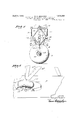
The details in the construction of a preferred embodiment of my invention, together with other objects attending its production, will be best understood from the following description of the accompanying drawings which are chosen for illustrative purposes only, and in which Fig. l'is a side elevation of an amphibian of the monoplane type, which is equipped with a preferred form of my invention;
Fig.2 is afront elevation of the plane shown in Fig. 1, which is partly broken away i from the hull so as to give the proper balance and may be considered as having been taken A V in the direction of the arrow 2 in Fig. 1;
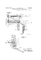
Fig. 3 is an enlarged sectional elevation showing details in the construction of the wheel assembly embodying my invention;
Fig. 4 is an end View of the wheel assembly shown in Fig. 3, showing the frame work with the housing removed, and may be considered as having been taken in the direction of the arrow 4 in Fig. 3;
Fig. 5 is an enlarged sectional. vlewtaken in a plane represented by the line 55 in Fig. 4;
ig. 6 is a partial side elevation similar to Fig. 1, showing the manner in which the landing wheel may be retracted into a horizontal position for landing the plane upon the water. A
More particularly descr'bing the invention as herein illustrated, re erence numeral 11 indicates an airplane of the amphibian monoplane type whlch consists of a hull or body 12 supporting, through the medium of struts 13 and 13, a wing 14. The wing 14 is shown as carrying a motor 15 and a propeller 16. Reference numeral 17 indicates the combination landing gear and stabilizing float contemplated by this invention.
The combination landing gear and stabilizing float 17 j is shown as consisting of a pair of out- right frames 18 and 18 which are enclosed within housings 19 and 19' and are shown as being yieldably mounted on opposite sides of the hull or fuselage and as being connected to the wings through the medium of. struts 14a, 14a, 14b and 14?).
In the form of my invention chosen for the segment 35 and the worm 36 are enclosed in purpose of illustration, the frames 18 and.
18 are shown as being in the form of open boxes consisting of horizontal members 20, upright members 21 and transverse members 22. The lower outer end portions of the frames 18 and 18' are adapted to support rotatable shafts indicated by reference numerals 23. The shafts 23, which are mounted on suitable bearings 24, have rigidly mounted thereon swinging frames 25 which are also made in the form of open box members comprising standards 26 and 27 and angular race members 28. The outer or lower end portions of the standards 26 and 27 are provided with bearings 29 and 29' which support the axle 30 of the landing wheel 31. The upper outer end portion of the rigid frame 17 1s provided with a stop member 32 which is adaptedto be engaged by a suitably positioned engagement member 33 on the swinging frame 25 when this last mentioned frame is swung to the horizontal position indicated in broken lines at A in Figures 2 and 3. The
swinging frames 25 are provided with housings 25a which are stream lined to reduce fiyin resistance and are provided with air cham ers 25b designed to act as pontoons and aid the wheels 31 in stabilizing the hull when the plane is in the water.
It will be understood, of course, that various means may beemployed for imparting angular adjustment to the swinging frame 25 with respect to the rigid frame 17. In the form of my invention chosen for the purpose of illustration, I show these adjusting means as comprising a worm wheel segment 35 which is rigidly mounted upon the midportion of the shaft 23 and is adapted to be engaged by a worm 36. Both the worm wheel aligned bearings 38 and 38 adapted to form a support for a shaft 39 which extends through and is rigidly attached to the worm 36. Reference character 35a indicates a control arm which is rigidly mounted on the shaft 23 and has its outer end portion attached to the point of intersection of the two angular braces 28. The shaft 39 is connected through the medium of a universal joint 40, with a main control shaft 41, which may be operated from the hull of the amphibian in any suitable manner, such as by means of a gear or sprocket 42 mounted on the inner end of the shaft 41. This sprocket may be associated with a corresponding sprocket on the wheel assembly at the opposite side of the hull and both sprockets maybe operated through the medium of a chain 44 and a crank 45 which is positioned adjacent the pilots seat.
Various other means, such as electric or hydraulic units, may be employed for effecting :the swinging movement of the wheels, and it is to be understood, as pointed out above, that the particular construction shown has been chosen for illustrative purposes only.
In the use of the landing gear contemlated by this invention, the wheels are placed in thefull line position shown in Fig. 1 when the craft is to be landed upon the ground. As pointed out above, means are provided for absorbing the shock incurred during ground landings, such means'being shown as comprising'the connection between the so-called rigid or outright frames 18 and 18 and the hull. Figure 3 shows the details in a preferred form of such connection and illustrates the same as comprisin thick rubber washers 50 which are enclose within housings 51. The frames are connected to the hull bv means of pivoted bolts 52 which have enlarged shoulders 53 projecting through apertures 54 in the side of the hull. The bolts 52 extend through the washers 50 and are secured thereon by means of washers 55 and nuts 56. From this construction it will be seen that the frame 18 is permitted to have a limited swinging movement with respect to the hull, and that the yieldable members 50 will absorb most of the shock incurred when the wheels first strike the ground.
When the plane is to be landed on water the wheels are withdrawn to the position B (Fig. 2), so that the wheels 31 and a part. of the pontoon shields or housings 25a extend below the water line C. The angle of the swinging frames may, as pointed out above, be adjusted to compensate for various loads in the hull. When the plane is being drawh up to a dock, the swinging frames are exviding a revolving bumper.
It is well known to those familiar with the art that, in view of the necessity of using ,pontoons on hydro airplanes, it has heretofore been considered impractical to employ monoplane construction in this type of craft, since the pontoons have always been mounted on the bottom wing. My invention makes possible the,,use of monoplane construction in hydro airplanes, since the stabilizing members are mounted on the hull, eliminating the cantilever action which would be incurred in the wings in the event pontoons were sus pended therefrom.
It will be apparent from the foregoing description, that the device contemplated by this invention provides a compact and stable landing gear for amphibians, which when .in a partially retracted position for landing on water, provides the stabilizing floats for the v hull, and when in a full retracted position provides a dock bumper. This organization greatly reduces the parasite resistance on air craft of this nature, since it may be thought of astdisplacing the pontoons or floats which are ordinarily required to stabilize the hull.
As pointed out above, the retracted wheels have the additional function of providing a revolving bumper which protects the hull and the wings when the amphibianv is being drawn up toa dock or landing platform.
It is to be understood that while I have herein described and illustrated one preferred form of my invention, the same is notlimited to the precise description above, but includes within its scope whatever changes fairly come within the spirit of the appended claims.
I claim as my invention:
1. For use in combination with the hull of a hydro airplane, a landing gear embodying:
wheels swingably carried on opposite sides of' said hull and adapted to be swung from vertical positions, where they act as ground wheels, to angular positions where they act as stabilizing floats, and to horizontal positions where they act as revolving bumpers.
2. For use in combination with the hull of a hydro airplane, a landing gear embodying: wheels swingably carried on opposite sides of said hull and adapted to be swung from vertical positions, where they act as ground wheels, to angular positions where they act as stabilizing floats, andto horizontal positions where they act as revolving bumpers;
and means for swinging said wheels.
- 3. For use in combination with the hull of a hydro airplane, a landing gear embodying: wheels swingably carried on opposite sides of said hull and adapted to be swung from vertical positions, where they act as ground wheels, to angular positions where they act as stabilizing floats, and to horizontal positions where they act as revolving bumpers; means for swinging said wheelsjand means for locking said wheels in various positions of angular adjustment.
4:. For use in combination with the hull of i a hydro airplane, a landing gear embodying: wheels swingably carried on opposite sides of said hull and adapted to be swung from ver- ,tical positions, where they act as ground wheels, to angular positions where they act as stabilizing floats, and to horizontal positions where they act as revolving bumpers; means including a worm for swinging said wheels; means for locking said wheels invarious positions of angular adjustment; and
stop means for limiting the upward swinging movement of said wheels.
, 6. For use in combination with the hull of a hydro airplane, a landing gear embodying: frame members mounted on opposite sides of said hull; yieldable means connecting said frame member to saidvhull; swinging frames mounted in said first mentioned frames and adapted to swing about axes parallel with the longitudinal axis of said hull; and landing wheels rotatablymounted in said swinging frame.
7 For use in combination with the hull of a hydro airplane, a landing gear embodying:
frame members mounted on opposite sides of said hull; yielding means connectin said frame member to said hull; swinging rames mounted in said first mentioned frames and adapted to swing about axes parallel with the longitudinal axis of said. hull; landingwheels rotatably mounted in said swinging frame and housings on said'swinging frames partially enclosing said landing wheels.
8. For use in combination with the hull of a' hydro airplane, a landing gear embodying:
' frame members mounted on opposite sides of said hull; yieldable means connecting said frame members tosaid hull swinging frames mounted in said first mentioned frames and adapted to swing about axes parallel with the longitudinal axis of said hull; landing wheels rotatably mounted in said swinging frame; andpontoonhousings on said swinging frames partially enclo'smg said landing wheels.
' In testimony whereof, I have hereunto set my hand at Los Angeles, California, this 15th day of April, 1930. HARVEY A. BEILGARD.
Priority Applications (1)
| Application Number | Priority Date | Filing Date | Title |
|---|---|---|---|
| US445852A US1852691A (en) | 1930-04-21 | 1930-04-21 | Combination landing gear, stabilizing float, and revolving bumper for hydroairplanes |
Applications Claiming Priority (1)
| Application Number | Priority Date | Filing Date | Title |
|---|---|---|---|
| US445852A US1852691A (en) | 1930-04-21 | 1930-04-21 | Combination landing gear, stabilizing float, and revolving bumper for hydroairplanes |
Publications (1)
| Publication Number | Publication Date |
|---|---|
| US1852691A true US1852691A (en) | 1932-04-05 |
Family
ID=23770449
Family Applications (1)
| Application Number | Title | Priority Date | Filing Date |
|---|---|---|---|
| US445852A Expired - Lifetime US1852691A (en) | 1930-04-21 | 1930-04-21 | Combination landing gear, stabilizing float, and revolving bumper for hydroairplanes |
Country Status (1)
| Country | Link |
|---|---|
| US (1) | US1852691A (en) |
Cited By (4)
| Publication number | Priority date | Publication date | Assignee | Title |
|---|---|---|---|---|
| DE1220742B (en) * | 1963-10-02 | 1966-07-07 | Hermann Wurster Dr Ing | Amphibious flying boat with support floats |
| US6113028A (en) * | 1996-02-22 | 2000-09-05 | Lohse; James R. | Amphibious aircraft |
| US7188804B1 (en) | 2004-06-25 | 2007-03-13 | Boetto Steven C | Float retractable landing gear |
| US20250145287A1 (en) * | 2021-11-05 | 2025-05-08 | My Atg Aircraft Technologies Group Inc. | Attachment for an amphibious aircraft |
-
1930
- 1930-04-21 US US445852A patent/US1852691A/en not_active Expired - Lifetime
Cited By (5)
| Publication number | Priority date | Publication date | Assignee | Title |
|---|---|---|---|---|
| DE1220742B (en) * | 1963-10-02 | 1966-07-07 | Hermann Wurster Dr Ing | Amphibious flying boat with support floats |
| US6113028A (en) * | 1996-02-22 | 2000-09-05 | Lohse; James R. | Amphibious aircraft |
| US6367737B1 (en) * | 1996-02-22 | 2002-04-09 | James R. Lohse | Amphibious aircraft |
| US7188804B1 (en) | 2004-06-25 | 2007-03-13 | Boetto Steven C | Float retractable landing gear |
| US20250145287A1 (en) * | 2021-11-05 | 2025-05-08 | My Atg Aircraft Technologies Group Inc. | Attachment for an amphibious aircraft |
Similar Documents
| Publication | Publication Date | Title |
|---|---|---|
| US3221831A (en) | Winged surface effect vehicles | |
| US1852691A (en) | Combination landing gear, stabilizing float, and revolving bumper for hydroairplanes | |
| US1568765A (en) | Helicopter | |
| US1512912A (en) | Aeroplane | |
| US2021439A (en) | Retractable landing gear | |
| GB143591A (en) | Improvements in or relating to aerial craft | |
| US2153266A (en) | Retractable hydrostabilizer for airplanes | |
| US1756463A (en) | Combined automobile and aeroplane | |
| US1929630A (en) | Landing gear for aircraft | |
| US1765328A (en) | Amphibian aircraft | |
| US1329533A (en) | Folding landing-gear for aircraft | |
| US1704076A (en) | Amphibian aeroplane without boat-shaped pontoons | |
| US2044338A (en) | Retractable landing gear | |
| US2392439A (en) | Airplane | |
| US1859624A (en) | Retractable landing gear for airplanes | |
| US1794813A (en) | Amphibian aeroplane | |
| US1765329A (en) | Amphibian aircraft | |
| US2051021A (en) | Retractable landing gear | |
| US1966309A (en) | Mounting for aircraft motors | |
| US2053093A (en) | Amphibian landing gear | |
| US2097990A (en) | Adjusting means for control surfaces | |
| US1779801A (en) | Airplane landing gear | |
| GB427185A (en) | Improvements in and relating to landing gear for aircraft | |
| US1545505A (en) | Airplane | |
| US1784784A (en) | Amphibian plane |