US1852690A - Reamer - Google Patents
Reamer Download PDFInfo
- Publication number
- US1852690A US1852690A US428477A US42847730A US1852690A US 1852690 A US1852690 A US 1852690A US 428477 A US428477 A US 428477A US 42847730 A US42847730 A US 42847730A US 1852690 A US1852690 A US 1852690A
- Authority
- US
- United States
- Prior art keywords
- reamer
- blades
- pilots
- shank
- pilot
- Prior art date
- Legal status (The legal status is an assumption and is not a legal conclusion. Google has not performed a legal analysis and makes no representation as to the accuracy of the status listed.)
- Expired - Lifetime
Links
- 230000008602 contraction Effects 0.000 description 1
Images
Classifications
-
- B—PERFORMING OPERATIONS; TRANSPORTING
- B23—MACHINE TOOLS; METAL-WORKING NOT OTHERWISE PROVIDED FOR
- B23D—PLANING; SLOTTING; SHEARING; BROACHING; SAWING; FILING; SCRAPING; LIKE OPERATIONS FOR WORKING METAL BY REMOVING MATERIAL, NOT OTHERWISE PROVIDED FOR
- B23D77/00—Reaming tools
- B23D77/06—Reaming with means for compensating wear
- B23D77/08—Reaming with means for compensating wear by spreading slotted parts of the tool body
-
- Y—GENERAL TAGGING OF NEW TECHNOLOGICAL DEVELOPMENTS; GENERAL TAGGING OF CROSS-SECTIONAL TECHNOLOGIES SPANNING OVER SEVERAL SECTIONS OF THE IPC; TECHNICAL SUBJECTS COVERED BY FORMER USPC CROSS-REFERENCE ART COLLECTIONS [XRACs] AND DIGESTS
- Y10—TECHNICAL SUBJECTS COVERED BY FORMER USPC
- Y10T—TECHNICAL SUBJECTS COVERED BY FORMER US CLASSIFICATION
- Y10T408/00—Cutting by use of rotating axially moving tool
- Y10T408/83—Tool-support with means to move Tool relative to tool-support
- Y10T408/85—Tool-support with means to move Tool relative to tool-support to move radially
- Y10T408/858—Moving means including wedge, screw or cam
- Y10T408/8583—Moving means including wedge, screw or cam with resiliently urged Tool
- Y10T408/85843—Resilient Tool or tool-support
Definitions
- My invention relates to expansion reamers for general use in hand or machine reaming operations.
- the principal object of the invention is to provide a reamer which will produce perfectly round and straight holes.
- Another object of the invention is to provide right and left hand angled cutting blades one in advance of the other so that the second or following blades will remove all marks or rough parts left by the first or primary cutters.
- Another object of the invention is to provide pilot members integrally formed with the reamer shank adjacent the respective cutting blades to insure substantially simultaneous and uniform expansion of these members.
- Another object of the invention is to position the pilots sufficiently close to the front and rear ends of the respective cutting blades to permit of accurate piloting in the reaming of comparatively short bearings, such as connecting rod bearings.
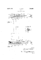
- Figure 1 is a side elevation of a reaming cutter embodying the invention, and shows in outline a connecting rod bearing to which the reamer is applied, the reamer being shown as it appears at the beginning of the reaming operation.
- Figure 2 is a longitudinal section of the reamer showing the means for expanding the cutting blades and pilots;
- Figure 3 is a section on the line 33 of Figure 2.
- Right and left hand angled cutting blades 7 and 8 respectively are integrally formed 011 the reamer shank approximately intermediate the ends thereof. Adjacent the outer ends of the respective groups of cutters are pilots 9 and 10, also integrally formed on the reamer shank, and in order to impart flexibility to the blades and to the pilots, that is permit expansion and contraction of these parts, by means of the expander 7 elongated slots 11 are cut or otherwise formed therein. These slots extend through and for a substantial distance beyond each end of that portion of the shank upon which the cutting blades are formed and are all preferably parallel to the axis of the reamer.
- the opposing angularity of blades and their parallel expansive action results in a better bearing hole being reamed.
- the first set of blades reams or trues the hole while the second set removes the marks or rough places left by the first set, thus producing a perfectly smooth straight bearing surface. It will also be noted that by locating the pilots adjacent the cutting blades that the reaming of very short holes, such as connecting rod bearings or the like, can be effectively accomplished.
- the pilot 9 is separated from the rearwardmost blades 7 by a groove 12, and at its forward edge is formed with short cutting blades 13, which align with and are in effect continuations of the blades 7
- a groove 14 similar to the groove 12, but of slightly less depth separates the forward pilot 10 from the foremost or leading blades 8, in alinement with short continuations 16 formed in the rear edge of the pilot 10.
- Each blade 7 and its corresponding blade 8 terminates in and is separated at its forward and rear end respectively by a broken circular groove 19.
- the bore 4 of the reamer is larger at its forward end than at its rear end, it is desirable to have the groove 12 slightly deeper than the groove 14 in order to get parallel expansion of the blades.
- the rea-mer 1 is inserted in the 19 bore 20 of the connecting rod 21, or other part to be reamed.
- the reaming can be effected by means of a Wrench or other tool applied to the end 3 of the reamer or the latter may be connected to a suitable machine.
- the pilot 10 guides and steadies the cutting blades in the bore 20, and as the pilot 10 leaves the bore the pilot 9 enters and functions during the remainder of the operation.
- a reamer comprising a differentially bored shank, eXpansible cutting blades on said shank, expansible pilots integrally formed on said shank adj acent said blades, said shank having circular grooves separating the blades from the pilots, one of said grooves being deeper than the other to compensate for the variation in size of the bore, and means for 3 expanding the blades and pilots.
Landscapes
- Engineering & Computer Science (AREA)
- Mechanical Engineering (AREA)
- Milling, Broaching, Filing, Reaming, And Others (AREA)
Description
April 1932- o BEARD I 1,852,690
REAMER Filed Feb. 14, 1930 TPatentecl Apr. 5, 1932 UNITED STATES PATENT OFFICE LAWRENCE O. BEARD, OF LANCASTER, PENNSYLVANIA REAMER Application filed February 14, 1930. Serial No. 428,477.
My invention relates to expansion reamers for general use in hand or machine reaming operations.
The principal object of the invention is to provide a reamer which will produce perfectly round and straight holes.
Another object of the invention is to provide right and left hand angled cutting blades one in advance of the other so that the second or following blades will remove all marks or rough parts left by the first or primary cutters.
Another object of the invention is to provide pilot members integrally formed with the reamer shank adjacent the respective cutting blades to insure substantially simultaneous and uniform expansion of these members.
Another object of the invention is to position the pilots sufficiently close to the front and rear ends of the respective cutting blades to permit of accurate piloting in the reaming of comparatively short bearings, such as connecting rod bearings.
Other and more specific objects and advantages of the invention will be apparent as the specification is considered in connection with the accompanying drawings, in which:
Figure 1 is a side elevation of a reaming cutter embodying the invention, and shows in outline a connecting rod bearing to which the reamer is applied, the reamer being shown as it appears at the beginning of the reaming operation.
Figure 2 is a longitudinal section of the reamer showing the means for expanding the cutting blades and pilots; and
Figure 3 is a section on the line 33 of Figure 2.
pprpose of which will be explained hereina ter.
Right and left hand angled cutting blades 7 and 8 respectively are integrally formed 011 the reamer shank approximately intermediate the ends thereof. Adjacent the outer ends of the respective groups of cutters are pilots 9 and 10, also integrally formed on the reamer shank, and in order to impart flexibility to the blades and to the pilots, that is permit expansion and contraction of these parts, by means of the expander 7 elongated slots 11 are cut or otherwise formed therein. These slots extend through and for a substantial distance beyond each end of that portion of the shank upon which the cutting blades are formed and are all preferably parallel to the axis of the reamer.
l/Vhen the cutting faces of the blades 7 and 8 of the reamer 1 wear down, or when it is desired to increase their cutting capacity, expander 7 is screwed home in the bore 4 until the beveled end 17 of the member 7 engages the shoulder 18, thus causing the flexible or expansible blades and pilots to expand practically simultaneously and uniformly.
The opposing angularity of blades and their parallel expansive action results in a better bearing hole being reamed. The first set of blades reams or trues the hole while the second set removes the marks or rough places left by the first set, thus producing a perfectly smooth straight bearing surface. It will also be noted that by locating the pilots adjacent the cutting blades that the reaming of very short holes, such as connecting rod bearings or the like, can be effectively accomplished.
The pilot 9 is separated from the rearwardmost blades 7 by a groove 12, and at its forward edge is formed with short cutting blades 13, which align with and are in effect continuations of the blades 7 It will also be noted that a groove 14 similar to the groove 12, but of slightly less depth, separates the forward pilot 10 from the foremost or leading blades 8, in alinement with short continuations 16 formed in the rear edge of the pilot 10. Each blade 7 and its corresponding blade 8 terminates in and is separated at its forward and rear end respectively by a broken circular groove 19. As the bore 4 of the reamer is larger at its forward end than at its rear end, it is desirable to have the groove 12 slightly deeper than the groove 14 in order to get parallel expansion of the blades.
In practice the rea-mer 1, is inserted in the 19 bore 20 of the connecting rod 21, or other part to be reamed. The reaming can be effected by means of a Wrench or other tool applied to the end 3 of the reamer or the latter may be connected to a suitable machine. 15 During the first part of the reaming operation the pilot 10 guides and steadies the cutting blades in the bore 20, and as the pilot 10 leaves the bore the pilot 9 enters and functions during the remainder of the operation. Q. Having thus described my invention What I claim is:
A reamer comprising a differentially bored shank, eXpansible cutting blades on said shank, expansible pilots integrally formed on said shank adj acent said blades, said shank having circular grooves separating the blades from the pilots, one of said grooves being deeper than the other to compensate for the variation in size of the bore, and means for 3 expanding the blades and pilots.
In testimony whereof I aflix my signature.
LAWRENCE o. BEARD.
Priority Applications (1)
| Application Number | Priority Date | Filing Date | Title |
|---|---|---|---|
| US428477A US1852690A (en) | 1930-02-14 | 1930-02-14 | Reamer |
Applications Claiming Priority (1)
| Application Number | Priority Date | Filing Date | Title |
|---|---|---|---|
| US428477A US1852690A (en) | 1930-02-14 | 1930-02-14 | Reamer |
Publications (1)
| Publication Number | Publication Date |
|---|---|
| US1852690A true US1852690A (en) | 1932-04-05 |
Family
ID=23699061
Family Applications (1)
| Application Number | Title | Priority Date | Filing Date |
|---|---|---|---|
| US428477A Expired - Lifetime US1852690A (en) | 1930-02-14 | 1930-02-14 | Reamer |
Country Status (1)
| Country | Link |
|---|---|
| US (1) | US1852690A (en) |
Cited By (2)
| Publication number | Priority date | Publication date | Assignee | Title |
|---|---|---|---|---|
| US2514121A (en) * | 1944-11-30 | 1950-07-04 | Curtiss Wright Corp | Tool |
| DE1158791B (en) * | 1954-02-08 | 1963-12-05 | Merz A G Dulliken | Adjustable reamer |
-
1930
- 1930-02-14 US US428477A patent/US1852690A/en not_active Expired - Lifetime
Cited By (2)
| Publication number | Priority date | Publication date | Assignee | Title |
|---|---|---|---|---|
| US2514121A (en) * | 1944-11-30 | 1950-07-04 | Curtiss Wright Corp | Tool |
| DE1158791B (en) * | 1954-02-08 | 1963-12-05 | Merz A G Dulliken | Adjustable reamer |
Similar Documents
| Publication | Publication Date | Title |
|---|---|---|
| US1643679A (en) | Flue-sheet tool | |
| US3058199A (en) | Cutting tool | |
| US1017352A (en) | Combined drill, center-reamer, and countersink tool. | |
| MX2014011177A (en) | Drill. | |
| GB405440A (en) | Improvements in and relating to cutter tools of the insertable blade type | |
| US1499584A (en) | Tool for drilling or boring metals | |
| US2093986A (en) | Circular cutting tool | |
| USRE24924E (en) | Gun drilling tool | |
| US1852690A (en) | Reamer | |
| US1514704A (en) | Reamer | |
| US2479136A (en) | Reamer | |
| IE54386B1 (en) | Cutoff insert | |
| US571253A (en) | Drilling or boring tool | |
| US2030846A (en) | Adjustable burnishing reamer | |
| US1762111A (en) | Angular serrated adjustable cutter | |
| US1946416A (en) | Glaze cutter | |
| US2439422A (en) | Shearing tool | |
| US2178384A (en) | Boring tool | |
| US1951100A (en) | Inserted blade cutter | |
| US1470545A (en) | Reamer | |
| US700736A (en) | Milling-machine cutter. | |
| US1725515A (en) | Method of sharpening hollow or mortiser chisels | |
| US1963767A (en) | Adjustable reamer | |
| US1752262A (en) | Bit for boring long holes | |
| US2215939A (en) | Boring-routing tool |