US1852685A - Powder dispenser - Google Patents
Powder dispenser Download PDFInfo
- Publication number
- US1852685A US1852685A US484157A US48415730A US1852685A US 1852685 A US1852685 A US 1852685A US 484157 A US484157 A US 484157A US 48415730 A US48415730 A US 48415730A US 1852685 A US1852685 A US 1852685A
- Authority
- US
- United States
- Prior art keywords
- receptacle
- cap
- air
- powder
- dispensing
- Prior art date
- Legal status (The legal status is an assumption and is not a legal conclusion. Google has not performed a legal analysis and makes no representation as to the accuracy of the status listed.)
- Expired - Lifetime
Links
- 239000000843 powder Substances 0.000 title description 16
- 239000000463 material Substances 0.000 description 7
- FPAFDBFIGPHWGO-UHFFFAOYSA-N dioxosilane;oxomagnesium;hydrate Chemical compound O.[Mg]=O.[Mg]=O.[Mg]=O.O=[Si]=O.O=[Si]=O.O=[Si]=O.O=[Si]=O FPAFDBFIGPHWGO-UHFFFAOYSA-N 0.000 description 4
- 241001477893 Mimosa strigillosa Species 0.000 description 3
- 238000012856 packing Methods 0.000 description 2
- 102000004726 Connectin Human genes 0.000 description 1
- 108010002947 Connectin Proteins 0.000 description 1
- 230000006835 compression Effects 0.000 description 1
- 238000007906 compression Methods 0.000 description 1
- 239000004744 fabric Substances 0.000 description 1
- 239000012850 fabricated material Substances 0.000 description 1
- 210000003811 finger Anatomy 0.000 description 1
- 239000012530 fluid Substances 0.000 description 1
- 239000011521 glass Substances 0.000 description 1
- 239000008187 granular material Substances 0.000 description 1
- 239000010985 leather Substances 0.000 description 1
- 210000002445 nipple Anatomy 0.000 description 1
- 229940099990 ogen Drugs 0.000 description 1
- 239000004482 other powder Substances 0.000 description 1
- 238000005507 spraying Methods 0.000 description 1
- 210000003813 thumb Anatomy 0.000 description 1
Images

Classifications
-
- A—HUMAN NECESSITIES
- A45—HAND OR TRAVELLING ARTICLES
- A45D—HAIRDRESSING OR SHAVING EQUIPMENT; EQUIPMENT FOR COSMETICS OR COSMETIC TREATMENTS, e.g. FOR MANICURING OR PEDICURING
- A45D33/00—Containers or accessories specially adapted for handling powdery toiletry or cosmetic substances
- A45D33/02—Containers or accessories specially adapted for handling powdery toiletry or cosmetic substances with dispensing means, e.g. sprinkling means
Definitions
- This invention relates to improvements in powder distributors and comprises a receptacle having an upper open end adapted to be closed by a cover having incorporated therein a flexible or other pressure creating device with a tube communicating from the pressure device to the interior of the receptacle, whereby an air current may be set up within the receptacle to agitate the contents thereof.
- the invention also comprises a novel form of outlet or spraying device which may be in the form of an applicator or may include a fabricated ad similar to a convent-ional powder puff? 4
- An object of this invention,-is to provide a device of the above mentioned character adapted to be positioned on an ordinary powder can in which talcum powder is dispensed for replacing the sifter cap usually accompanying powder receptacles of this type.
- a further object of this invention is to provide a novel support for the flexible compressible air bulb in combination with the recept acle and the removable cap, or dispensing device.
- a still further object of this invention is to provide a device of the above mentioned character in which the air feed pipe projects downwardly at an angle to the bottom of the receptacle to create a turbulenceof the material therein and feeding the same out through the dispensing opening.
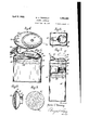
- Figure 1 is a top elevation of a preferred
- Figure 2 is a vertical cross-section of the receptacle illustrating the manner in which the cap is secured to the neck'of the receptacle and illustrating the manner in which the com-' pressible bulb is carried by the cap;
- Figure 3 is a transverse cross-sectional view, taken on line 3- 3 of Figure 2, illustrating the container and the provision of the flexible compressible bulb seated in the novel support;
- Figure 4 is a top elevation of a modified form of the invention, illustrating the flexible compressiblemember carried by the remov-- able cap and illustrating the dispensing noz-; zle removed;
- Figure 5 is a side elevation of the device illustrated in Figure 4 partly in section, illustratlng the manner in which the flexible compressible member is seated in a concaved portion of the cap and showing the manner 30 in which the tube leading from the compressible member is presented to the interior of the receptacle;
- Figure 6 is a still further modified form of the invention illustrating a different form of air supply device including a dash pot structure carried by the removable cap of the powder receptacle;
- Figure 7 is a side elevation of the device illustrated in Figure 6, showing the receptacle partly in section to illustrate the construct-ionof the dash pot air compressor for feeding air to the interior of the powder can or receptacle;
- Fi re 8 is a cross-sectional view of a now or applicator adapted to be removably secured to the dispensing nozzle of the powder can; 7
- Figure 9 is a top elevation of the'powder applicator illustrating the fabricated pad and the contour thereof; and I Figure 10 is a vertical side elevation of a' still further modified form of the invention showing an extended nozzle on the end of which is secured a flexible powder applicator, formed of a fabricated material.
- the reference character 10 will generally be employed to designate a container formed of glass or other material being oblong in crosssect-ion and of a bulbous shape in side-elevation.
- a neck portion 11 is formed at the upper end of the receptacle 10, terminating in an enlarged lip 12 of annular contour.
- the neck 11 and lip 12 are provided with a circular cap 13 having an angular exten-' sion 14 forming an outlet which is perfo rated as at tegr with the cap, and the extension 18 terminates in an angular portion 19 bent downwardly forming a spoon-shaped element 20 which is presented angularly to the receptacle 10.
- a flexible rubber bulb 21 Seated within the concaved spoon-shaped member is a flexible rubber bulb 21 and the bulb 21 may be held in place relative to the concave spoon member 20 by lacing 22 as clearly illustrated in Figures 1 and 2.
- the upper end of the flexible bulb 21 is provided with a nipple 23 to which is secured a metallic tube 24 which extends upwardly and is bent over in the same plane as the radial extension 17 of the cap.
- the free end of the tube 24 passes through an opening 25 formed in the cap 13 and extends downwardly as at 26 in order that the open end thereof may be presented downwardly atan angle to the receptacle 10.
- Figure 3 clearly illustrates the concave spoon member 20 which is formed as an integral part of the radial extension 17 forme on the cap 13.
- Figures 4 and 5 wherein is illustrated a modified form of the invention and wherein the reference character 27 designates a receptacle of the talcum powder type which is oval in transverse crosssection and which is provided with an open upper end having an annular flange 28 to form. a stop for a removable cap 29 which is of the same transverse cross-section as the receptacle 27
- the cap 29 is provided with a downwardly extendingflange 30 whereby the cap may be frictionally held on the receptacle 27.
- the cap 29 is provided with a dispensing nozzle- 31 having a plurality of apertures.
- the dispensing nozzle 31 may be presented at an angle from the cap 29 and may be provided with a metallic applicator 34 having a flexible pad or cloth member 35 held in place by a metallic ring 36 engaging the edges of the pad 35 and holding the same in a recess 37 near the outer edge of the applicator 34.
- the applicator 34 is provided with an annular flange 38 whereby the flange 38 may receive the nozzle 31 and be 'frictionally held thereon.
- a concaved portion 39 is formed in the cap 29 for receiving a flexible compressible member 40 of the same general contour as the elongated concaved portion 39 and a metallic plate 41 may be secured to the flexible member 40 for manually compressing the member 40 and causing air to be forced through the tube 42 which has one of its ends connected to the flexible chamber '40 as at 43 and its opposite end or openend bent downtherefrom and formed integral.
- tangular in transverse cross-section and the receptacle 45 may be of the conventional talcum powder type in which talcum powder or other powder is dispensed.
- the receptacle 45 is provided with a removable cap or cover 46 having a downwardly extending flanged portion 48 which fits over the upper open end of the receptacle 45 and is held therein in a frictional manner.
- the lower edge of the flange 48 is provided with a head 49 to strengthen and reinforce the cap.
- a dispensing nozzle 50 extends at an angle to the cap 48 and is provided with a series of apertures 51 through which the powder in the receptacle 45 is adapted to ass.
- a cylinder 52 Formed integral with the cap 48 is a cylinder 52 having its bottom end closed as at 53 and its upper end opened for the rece 'tion of a plunger 54 which is reci rocab y mounted within the cylinder 52 and 1s adapted to be held in a vertical normal position by means of a coil spring 55.
- a leather packmg element 56 is provided on the lower end of the plunger 54 and is held in place by a ring 57 engaging one edge of the packing element 56 and holding the same into engagement with the plunger in a-frictional manner.
- the free ed es of the packing member 56 extend radia y from the cylindrical plunger 54 and engage the cylinder wall of the cylinder 52.
- the upper end of the cylindrical plunger 54 is provided with a push button 57 whereby the finger or thumb of the operator may rest thereon while reciprocating the plunger 54 against the action of the coil spring 55.
- An air pipe 58 has one of its ends as at 59 secured to the bottom 53 of the cylinder 52 and the opposite end of the tube 58 is curved as at 60 in order that the open end may extend downwardly toward the bottom of the receptacle 45. In this manner, turbulence is also set up within the receptacle 45 in a manner similar to the devices illustrated in Figures 1 to 5 inclusive.
- Figure 10 is illustrated a still further modified form of the invention in which the reference character 61 designates a powder receptacle having an open upper end to which is secured a cap 62 having a nozzle 63 extending vertically therefrom and provided with a dish-shaped element 64 which is concaved and which is provided with a fabricated pad 65 in the form of a powder puff.
- the nozzle 63 is provided with a bore which communicates vwith the interior of the receptacle 61 and,
- the receptacle 61 may be provided with a concave side wall 70 in order to receive the compressible bulb 66 whereby the receptacle and bulb 66 may be held in one hand and operated to cause the contentsof the receptacle to be agitated and dispensed by means of air pressure.
- a receptacle comprising a receptacle, a removable cover .for the receptacle, a nozzleformed integral end, a removable cover frictionally held on the receptacle, a dispensing nozzle supported on a part of the cover, an air supply device carried by the cover, and an air feed pipe having one of its ends connected to the air supply device and extending into the receptac e with its open inner end angularly disposed adjacent a side wall of the receptacle whereby end, a removable cap for closing-the upper end of the receptacle, a dispensing nozzle extending angularly from the cap, formed integral therewith and in direct communication with the interior of the receptacle, an air supply device carried by the cap, and a pipe for feeding air from the air supply device to the interior of the receptacle in such a manner as to cause a turbulence within the receptacle to dispense the material therein in a substantially straight line
- a device of the character described comprising a receptacle having an open upper end, a removable cap or cover frictionally held on the open end of the receptacle, a dis-pensing nozzle presented at an angle to the cap and having a series of dispensing apertures and having a straight line communication with the interior of the receptacle, an air feeding and supplying device supported by the removal cap or cover, and a pipe connecting the air supply device with the interior of the receptacle in such a manner as to cause a turbulence therein for dispensing the contents of the receptacle.
- a device of the character described comprising a receptacle having an open upper end, a cap or cover removably secured to the open upper end of the receptacle, a dispensing nozzle extending angularly from the removable cover or cap, an air supply device carried by the removable cover or cap, and a pipe connecting the air supply device extending through the cap into the receptacle, having its open end presented angularly to the bottom wall of the receptacle, whereby'a turbulence will be set up within the receptacle for dispensing the contents thereof through the dispensing nozzle.
- a device of the character described comprising a receptacle,'a cap removably secured to the opening of the receptacle, a dispensing nozzle formed integral with the cap, a padded applicator carried by the outer end of the dispensing nozzle, and means for forcing air into the interior of the receptacle in such a manner as to cause a turbulence therein for dispensing the contents of the receptacle through the padded applicator.
- a device of the character described comprising a receptacle having an open upper end, a removable cap carried by the receptacle at the open end thereof, a concaved nozzle,
- an air ulb mounted withm the concaved portion of the top, and a pipe communicatin with the air bulb and wit the interior of e receptacle in' such a manner as to cause a turbulence therein for dispensing the contents throu h the removable cap.
- a cap removably carried by t e open end of the receptacle, a concaved portlon formed in a portion of the removable cap, a bulb of flexible material mounted within the concaved portion and held therein, a pi connectin one end of the bulb member to t e interior 0 the receptacle, the open end of the pipe being presented at. an angle to the bot-- tom of the receptacle whereby a turbulence will be set up therein and a dispensmg nozzle formed integral with the cap extending angularly therefrom.
- a device of the character described comprising a receptacle having an upper open end, a cap removably extending an arl from the removable cap, a fabricate app icator adapted to be carried by the outer end of the dispensing a concaved portion formed in a section of the cap, an air supply bulb seated within the concaved portion, means at one end for admitting air to the bulb, a pi connecting the opposite end of the bu b, said pipe extending within the receptacle and aving its open end presented at an angle to the bottom of the receptacle whereby a turbulence will be set up therein to cause the contents to be dispensed through the fabricated applicator.
- a device of the character described comprising'a receptacle having an open upper end, a remova 1e cap carried by t e ope end of the receptacle, a dispensing nozzle resented at an angle to the cap, an air bulb or su plying air to the receptacle, meansforme integral with the cap for supportin the air bulb, and a pipe connecting one end 0% the air bulb to the interior of the receptacle whereby the open end of the pipe will be presented at an angle to the bottom of the receptacle for causing a turbulence therein and causing the dispensing of the material nozzle.
Landscapes
- Closures For Containers (AREA)
Description
April 1932- M. v. TREMBLAY- 85 POWDER DISPENSER Filed Sept. 24, 1930 2 Shee'ts-Sheet l f 14 00444 ariau fi'emblay.
A ril 5, 1932. M. v. TREMBLAY POWDER DISPENSER Filed Sept. 24, 1930 2 Sheets-Sheet 2 Patented Apr. 5, 1:?32
umrao STATES JPATENT] OFFI'CE rownnn nrsrnnsnn Application filed September 24, 1930. Serial No. 484,157.
This invention relates to improvements in powder distributors and comprises a receptacle having an upper open end adapted to be closed by a cover having incorporated therein a flexible or other pressure creating device with a tube communicating from the pressure device to the interior of the receptacle, whereby an air current may be set up within the receptacle to agitate the contents thereof. The invention also comprises a novel form of outlet or spraying device which may be in the form of an applicator or may include a fabricated ad similar to a convent-ional powder puff? 4 An object of this invention,-is to provide a device of the above mentioned character adapted to be positioned on an ordinary powder can in which talcum powder is dispensed for replacing the sifter cap usually accompanying powder receptacles of this type.
A further object of this invention, is to provide a novel support for the flexible compressible air bulb in combination with the recept acle and the removable cap, or dispensing device.
A still further object of this invention, is to provide a device of the above mentioned character in which the air feed pipe projects downwardly at an angle to the bottom of the receptacle to create a turbulenceof the material therein and feeding the same out through the dispensing opening.
Other objects and advantages of the invention will become apparent during the course of the following description, forming a part of the specification, and in which,
Figure 1 is a top elevation of a preferred,
embodiment of the invention illustrating the removable cap associated with the receptacle and the dispensing device secured thereto;
Figure 2 is a vertical cross-section of the receptacle illustrating the manner in which the cap is secured to the neck'of the receptacle and illustrating the manner in which the com-' pressible bulb is carried by the cap;
Figure 3 is a transverse cross-sectional view, taken on line 3- 3 of Figure 2, illustrating the container and the provision of the flexible compressible bulb seated in the novel support;
Figure 4 is a top elevation of a modified form of the invention, illustrating the flexible compressiblemember carried by the remov-- able cap and illustrating the dispensing noz-; zle removed;
Figure 5 is a side elevation of the device illustrated in Figure 4 partly in section, illustratlng the manner in which the flexible compressible member is seated in a concaved portion of the cap and showing the manner 30 in which the tube leading from the compressible member is presented to the interior of the receptacle;
Figure 6 is a still further modified form of the invention illustrating a different form of air supply device including a dash pot structure carried by the removable cap of the powder receptacle;
Figure 7 is a side elevation of the device illustrated in Figure 6, showing the receptacle partly in section to illustrate the construct-ionof the dash pot air compressor for feeding air to the interior of the powder can or receptacle;
Fi re 8 is a cross-sectional view of a now or applicator adapted to be removably secured to the dispensing nozzle of the powder can; 7
Figure 9 is a top elevation of the'powder applicator illustrating the fabricated pad and the contour thereof; and I Figure 10 is a vertical side elevation of a' still further modified form of the invention showing an extended nozzle on the end of which is secured a flexible powder applicator, formed of a fabricated material.
In the drawings, wherein for the purpose of illustrating the invention and wherein like reference characters will be employed to designate like parts throughout the same, the reference character 10 will generally be employed to designate a container formed of glass or other material being oblong in crosssect-ion and of a bulbous shape in side-elevation. A neck portion 11 is formed at the upper end of the receptacle 10, terminating in an enlarged lip 12 of annular contour. The neck 11 and lip 12 are provided with a circular cap 13 having an angular exten-' sion 14 forming an outlet which is perfo rated as at tegr with the cap, and the extension 18 terminates in an angular portion 19 bent downwardly forming a spoon-shaped element 20 which is presented angularly to the receptacle 10.
Seated within the concaved spoon-shaped member is a flexible rubber bulb 21 and the bulb 21 may be held in place relative to the concave spoon member 20 by lacing 22 as clearly illustrated in Figures 1 and 2. The upper end of the flexible bulb 21 is provided with a nipple 23 to which is secured a metallic tube 24 which extends upwardly and is bent over in the same plane as the radial extension 17 of the cap. The free end of the tube 24 passes through an opening 25 formed in the cap 13 and extends downwardly as at 26 in order that the open end thereof may be presented downwardly atan angle to the receptacle 10. Figure 3 clearly illustrates the concave spoon member 20 which is formed as an integral part of the radial extension 17 forme on the cap 13.
Attention is directed to Figures 4 and 5 wherein is illustrated a modified form of the invention and wherein the reference character 27 designates a receptacle of the talcum powder type which is oval in transverse crosssection and which is provided with an open upper end having an annular flange 28 to form. a stop for a removable cap 29 which is of the same transverse cross-section as the receptacle 27 The cap 29 is provided with a downwardly extendingflange 30 whereby the cap may be frictionally held on the receptacle 27. The cap 29 is provided with a dispensing nozzle- 31 having a plurality of apertures. 32 in the end thereof and the dispensing nozzle 31 may be presented at an angle from the cap 29 and may be provided with a metallic applicator 34 having a flexible pad or cloth member 35 held in place by a metallic ring 36 engaging the edges of the pad 35 and holding the same in a recess 37 near the outer edge of the applicator 34. The applicator 34 is provided with an annular flange 38 whereby the flange 38 may receive the nozzle 31 and be 'frictionally held thereon.
A concaved portion 39 is formed in the cap 29 for receiving a flexible compressible member 40 of the same general contour as the elongated concaved portion 39 and a metallic plate 41 may be secured to the flexible member 40 for manually compressing the member 40 and causing air to be forced through the tube 42 which has one of its ends connected to the flexible chamber '40 as at 43 and its opposite end or openend bent downtherefrom and formed integral.
tangular in transverse cross-section and the receptacle 45 may be of the conventional talcum powder type in which talcum powder or other powder is dispensed.
The receptacle 45 is provided with a removable cap or cover 46 having a downwardly extending flanged portion 48 which fits over the upper open end of the receptacle 45 and is held therein in a frictional manner. The lower edge of the flange 48 is provided with a head 49 to strengthen and reinforce the cap. A dispensing nozzle 50 extends at an angle to the cap 48 and is provided with a series of apertures 51 through which the powder in the receptacle 45 is adapted to ass. Formed integral with the cap 48 is a cylinder 52 having its bottom end closed as at 53 and its upper end opened for the rece 'tion of a plunger 54 which is reci rocab y mounted within the cylinder 52 and 1s adapted to be held in a vertical normal position by means of a coil spring 55. A leather packmg element 56 is provided on the lower end of the plunger 54 and is held in place bya ring 57 engaging one edge of the packing element 56 and holding the same into engagement with the plunger in a-frictional manner. The free ed es of the packing member 56 extend radia y from the cylindrical plunger 54 and engage the cylinder wall of the cylinder 52. The upper end of the cylindrical plunger 54 is provided with a push button 57 whereby the finger or thumb of the operator may rest thereon while reciprocating the plunger 54 against the action of the coil spring 55. An air pipe 58 has one of its ends as at 59 secured to the bottom 53 of the cylinder 52 and the opposite end of the tube 58 is curved as at 60 in order that the open end may extend downwardly toward the bottom of the receptacle 45. In this manner, turbulence is also set up within the receptacle 45 in a manner similar to the devices illustrated in Figures 1 to 5 inclusive.
In Figure 10 is illustrated a still further modified form of the invention in which the reference character 61 designates a powder receptacle having an open upper end to which is secured a cap 62 having a nozzle 63 extending vertically therefrom and provided with a dish-shaped element 64 which is concaved and which is provided with a fabricated pad 65 in the form of a powder puff. The nozzle 63 is provided with a bore which communicates vwith the interior of the receptacle 61 and,
is connected to the pipe 67 at whereby powder in the receptacle 61 may be fed to the powder puff element 65 by means of an air supply device in the form of a collapsible tube 66 connected to the cap 62 by means of a pipe 67.. An air sup ly pipe 68 t e juncture 69 and the air supply pipe 68 passes through the receptacle cap 62 and has its open end presented to the bottom of the receptacle 61. The receptacle 61 may be provided with a concave side wall 70 in order to receive the compressible bulb 66 whereby the receptacle and bulb 66 may be held in one hand and operated to cause the contentsof the receptacle to be agitated and dispensed by means of air pressure.
The operation of the device illustrated in Figures 1 to 10 inclusive will be readily understood and by operation of the air devices or compression members 21, and 54, air is forced through the respective tubes 26, 42 and 58 within the receptacles 10, 27 and 45. The tubes above described extend within the receptacle in such a manner that the open ends are presented to the bottom of the receptacle to agitate and cause a turbulence of the powder material within the receptacle whereby the powder material may be dispensed through the nozzle 14, 31 and respectively. The operation of the device as illustrated 1n Figure 10 is obvious and it is to be understood that the device is provided with an extension nozzle 63 whereby the fabricated pad 65 may be caused to reach diflicult parts of the body of the user.
It is also to be understood, that various changes in the shape, size and arrangement of parts may be resorted to without departing from the spirit of the invention or the scope of the sub-joined claims and that the forms of the invention herewith shown and described, are to be taken as the preferred embodiments of the invention, but the invention may be carried out in any number of devices in which dispensing of fluid or granular materials is necessary.
Having thus described the invention, what I clalm is 1. A device of the character described,
comprising a receptacle, a removable cover .for the receptacle, a nozzleformed integral end, a removable cover frictionally held on the receptacle, a dispensing nozzle supported on a part of the cover, an air supply device carried by the cover, and an air feed pipe having one of its ends connected to the air supply device and extending into the receptac e with its open inner end angularly disposed adjacent a side wall of the receptacle whereby end, a removable cap for closing-the upper end of the receptacle, a dispensing nozzle extending angularly from the cap, formed integral therewith and in direct communication with the interior of the receptacle, an air supply device carried by the cap, and a pipe for feeding air from the air supply device to the interior of the receptacle in such a manner as to cause a turbulence within the receptacle to dispense the material therein in a substantially straight line through the dis pensing nozzle of the cap.
4. A device of the character described, comprising a receptacle having an open upper end, a removable cap or cover frictionally held on the open end of the receptacle, a dis-pensing nozzle presented at an angle to the cap and having a series of dispensing apertures and having a straight line communication with the interior of the receptacle, an air feeding and supplying device supported by the removal cap or cover, and a pipe connecting the air supply device with the interior of the receptacle in such a manner as to cause a turbulence therein for dispensing the contents of the receptacle.
5. A device of the character described, comprising a receptacle having an open upper end, a cap or cover removably secured to the open upper end of the receptacle, a dispensing nozzle extending angularly from the removable cover or cap, an air supply device carried by the removable cover or cap, and a pipe connecting the air supply device extending through the cap into the receptacle, having its open end presented angularly to the bottom wall of the receptacle, whereby'a turbulence will be set up within the receptacle for dispensing the contents thereof through the dispensing nozzle.
6. A device of the character described, comprising a receptacle,'a cap removably secured to the opening of the receptacle, a dispensing nozzle formed integral with the cap, a padded applicator carried by the outer end of the dispensing nozzle, and means for forcing air into the interior of the receptacle in such a manner as to cause a turbulence therein for dispensing the contents of the receptacle through the padded applicator.
7. A device of the character described, comprising a receptacle having an open upper end, a removable cap carried by the receptacle at the open end thereof, a concaved nozzle,
ortion formed in a portion of the cap, an air ulb mounted withm the concaved portion of the top, and a pipe communicatin with the air bulb and wit the interior of e receptacle in' such a manner as to cause a turbulence therein for dispensing the contents throu h the removable cap.
8. device of the c aracter described,
comprising a receptacle having an ogen up-.
per end, a cap removably carried by t e open end of the receptacle, a concaved portlon formed in a portion of the removable cap, a bulb of flexible material mounted within the concaved portion and held therein, a pi connectin one end of the bulb member to t e interior 0 the receptacle, the open end of the pipe being presented at. an angle to the bot-- tom of the receptacle whereby a turbulence will be set up therein and a dispensmg nozzle formed integral with the cap extending angularly therefrom.
9. A device of the character described, comprising a receptacle having an upper open end, a cap removably extending an arl from the removable cap, a fabricate app icator adapted to be carried by the outer end of the dispensing a concaved portion formed in a section of the cap, an air supply bulb seated within the concaved portion, means at one end for admitting air to the bulb, a pi connecting the opposite end of the bu b, said pipe extending within the receptacle and aving its open end presented at an angle to the bottom of the receptacle whereby a turbulence will be set up therein to cause the contents to be dispensed through the fabricated applicator.
10. A device of the character described, comprising'a receptacle having an open upper end, a remova 1e cap carried by t e ope end of the receptacle, a dispensing nozzle resented at an angle to the cap, an air bulb or su plying air to the receptacle, meansforme integral with the cap for supportin the air bulb, and a pipe connecting one end 0% the air bulb to the interior of the receptacle whereby the open end of the pipe will be presented at an angle to the bottom of the receptacle for causing a turbulence therein and causing the dispensing of the material nozzle. I aflix my si ature.
v. TREMB AY.
through the dispensm In testimony whereo MARIA secured to the open end of the receptacle, a dispensing nozz e
Priority Applications (1)
| Application Number | Priority Date | Filing Date | Title |
|---|---|---|---|
| US484157A US1852685A (en) | 1930-09-24 | 1930-09-24 | Powder dispenser |
Applications Claiming Priority (1)
| Application Number | Priority Date | Filing Date | Title |
|---|---|---|---|
| US484157A US1852685A (en) | 1930-09-24 | 1930-09-24 | Powder dispenser |
Publications (1)
| Publication Number | Publication Date |
|---|---|
| US1852685A true US1852685A (en) | 1932-04-05 |
Family
ID=23922992
Family Applications (1)
| Application Number | Title | Priority Date | Filing Date |
|---|---|---|---|
| US484157A Expired - Lifetime US1852685A (en) | 1930-09-24 | 1930-09-24 | Powder dispenser |
Country Status (1)
| Country | Link |
|---|---|
| US (1) | US1852685A (en) |
Cited By (12)
| Publication number | Priority date | Publication date | Assignee | Title |
|---|---|---|---|---|
| US2672689A (en) * | 1951-09-15 | 1954-03-23 | Politziner Joseph | Hem marker |
| US2800673A (en) * | 1953-07-15 | 1957-07-30 | Lazisky Laura | Applicator for powders and liquids |
| WO2001052693A1 (en) * | 2000-01-17 | 2001-07-26 | The Aroma Company (Europe) Limited | Fragrance dispensing device |
| WO2003046386A1 (en) * | 2001-11-26 | 2003-06-05 | The Clorox Company | Repressurizing dispenser for carbonated beverage containers |
| US20040035884A1 (en) * | 2001-11-26 | 2004-02-26 | De La Guardia Mario Felix | Pressurizing device for attachment to fluid containers |
| US20040262340A1 (en) * | 2003-06-26 | 2004-12-30 | Spencer Forrest, Inc. | Applicator for hair building solids |
| US20050230426A1 (en) * | 2002-11-26 | 2005-10-20 | De La Guardia Mario F | Pressure sprayer |
| US8172115B1 (en) * | 2008-04-10 | 2012-05-08 | Spencer Forrest, Inc. | Hair building solids dispenser for one handed operation |
| US20120138633A1 (en) * | 2010-12-02 | 2012-06-07 | Buttercup Group, Inc. | Air Collecting and Expelling Amusement Device |
| US20170051483A1 (en) * | 2015-08-17 | 2017-02-23 | Gregory C. Dildilian | Manually cleanable drain trap |
| US20190255558A1 (en) * | 2018-02-20 | 2019-08-22 | Nick Dimakos | Applicators for applying fibers to surfaces |
| US20220151217A1 (en) * | 2020-11-16 | 2022-05-19 | S. C. Johnson & Son, Inc. | Diatomaceous earth and silica dust applicator |
-
1930
- 1930-09-24 US US484157A patent/US1852685A/en not_active Expired - Lifetime
Cited By (19)
| Publication number | Priority date | Publication date | Assignee | Title |
|---|---|---|---|---|
| US2672689A (en) * | 1951-09-15 | 1954-03-23 | Politziner Joseph | Hem marker |
| US2800673A (en) * | 1953-07-15 | 1957-07-30 | Lazisky Laura | Applicator for powders and liquids |
| US20030235522A1 (en) * | 2000-01-17 | 2003-12-25 | Simon Harrop | Fragrance dispensing device |
| WO2001052693A1 (en) * | 2000-01-17 | 2001-07-26 | The Aroma Company (Europe) Limited | Fragrance dispensing device |
| US6991136B2 (en) | 2001-11-26 | 2006-01-31 | De La Guardia Mario Felix | Pressurizing device for attachment to fluid containers |
| US20040035884A1 (en) * | 2001-11-26 | 2004-02-26 | De La Guardia Mario Felix | Pressurizing device for attachment to fluid containers |
| WO2003046386A1 (en) * | 2001-11-26 | 2003-06-05 | The Clorox Company | Repressurizing dispenser for carbonated beverage containers |
| EP1448898A4 (en) * | 2001-11-26 | 2006-06-28 | Clorox Co | Repressurizing dispenser for carbonated beverage containers |
| US7131558B2 (en) * | 2002-11-26 | 2006-11-07 | De La Guardia Mario Felix | Pressure sprayer |
| US20050230426A1 (en) * | 2002-11-26 | 2005-10-20 | De La Guardia Mario F | Pressure sprayer |
| US7140522B2 (en) * | 2003-06-26 | 2006-11-28 | Spencer Forrest, Inc. | Applicator for hair building solids |
| US20040262340A1 (en) * | 2003-06-26 | 2004-12-30 | Spencer Forrest, Inc. | Applicator for hair building solids |
| US8172115B1 (en) * | 2008-04-10 | 2012-05-08 | Spencer Forrest, Inc. | Hair building solids dispenser for one handed operation |
| US20120138633A1 (en) * | 2010-12-02 | 2012-06-07 | Buttercup Group, Inc. | Air Collecting and Expelling Amusement Device |
| US8490830B2 (en) * | 2010-12-02 | 2013-07-23 | Buttercup Group, Inc. | Air collecting and expelling amusement device |
| US20170051483A1 (en) * | 2015-08-17 | 2017-02-23 | Gregory C. Dildilian | Manually cleanable drain trap |
| US20190255558A1 (en) * | 2018-02-20 | 2019-08-22 | Nick Dimakos | Applicators for applying fibers to surfaces |
| US11511312B2 (en) * | 2018-02-20 | 2022-11-29 | Surethik | Applicators for applying fibers to surfaces |
| US20220151217A1 (en) * | 2020-11-16 | 2022-05-19 | S. C. Johnson & Son, Inc. | Diatomaceous earth and silica dust applicator |
Similar Documents
| Publication | Publication Date | Title |
|---|---|---|
| US1852685A (en) | Powder dispenser | |
| US3592365A (en) | Pump-type dispensing apparatus | |
| US2680010A (en) | Foam dispensing device | |
| US3450314A (en) | Dispensing valve having rubber-like dispensing head | |
| US3456850A (en) | Soap dispensing apparatus | |
| US5115948A (en) | Toothpaste dispenser with a flexible air compressing bag used to bring about dispensing | |
| US3085752A (en) | Pressure dispenser | |
| US1716525A (en) | Spraying or atomizing device | |
| US2202079A (en) | Dispenser | |
| US2381454A (en) | Machine for filling products into containers | |
| US2341950A (en) | Dispensing device | |
| US2153156A (en) | Fluid dispensing apparatus | |
| US2252542A (en) | Adhesive dispenser | |
| US1751129A (en) | Dispenser | |
| US1776489A (en) | Powder distributor | |
| US2907358A (en) | Tooth powder containers | |
| US2655407A (en) | Self-filling, hand-operated atomizer or spraying device | |
| US3127073A (en) | Dispensing device | |
| US2283093A (en) | Filling spout | |
| US2312730A (en) | Dispenser | |
| US2091518A (en) | Dispenser for liquids | |
| US2038915A (en) | Dispenser | |
| US2102749A (en) | Dispensing cap | |
| US2431081A (en) | Powder spray dispenser | |
| US3042085A (en) | Condiment holder |