US1852681A - Seal and bearing construction - Google Patents
Seal and bearing construction Download PDFInfo
- Publication number
- US1852681A US1852681A US519479A US51947931A US1852681A US 1852681 A US1852681 A US 1852681A US 519479 A US519479 A US 519479A US 51947931 A US51947931 A US 51947931A US 1852681 A US1852681 A US 1852681A
- Authority
- US
- United States
- Prior art keywords
- shaft
- casing
- seal
- rotating
- ring
- Prior art date
- Legal status (The legal status is an assumption and is not a legal conclusion. Google has not performed a legal analysis and makes no representation as to the accuracy of the status listed.)
- Expired - Lifetime
Links
- 238000010276 construction Methods 0.000 title description 13
- 238000007789 sealing Methods 0.000 description 11
- 230000006835 compression Effects 0.000 description 8
- 238000007906 compression Methods 0.000 description 8
- 239000012530 fluid Substances 0.000 description 3
- 238000004891 communication Methods 0.000 description 2
- 102100034742 Rotatin Human genes 0.000 description 1
- 101710200213 Rotatin Proteins 0.000 description 1
- 230000006870 function Effects 0.000 description 1
- 239000002184 metal Substances 0.000 description 1
- 238000012986 modification Methods 0.000 description 1
- 230000004048 modification Effects 0.000 description 1
- 238000005192 partition Methods 0.000 description 1
Images
Classifications
-
- F—MECHANICAL ENGINEERING; LIGHTING; HEATING; WEAPONS; BLASTING
- F16—ENGINEERING ELEMENTS AND UNITS; GENERAL MEASURES FOR PRODUCING AND MAINTAINING EFFECTIVE FUNCTIONING OF MACHINES OR INSTALLATIONS; THERMAL INSULATION IN GENERAL
- F16J—PISTONS; CYLINDERS; SEALINGS
- F16J15/00—Sealings
- F16J15/16—Sealings between relatively-moving surfaces
- F16J15/34—Sealings between relatively-moving surfaces with slip-ring pressed against a more or less radial face on one member
- F16J15/36—Sealings between relatively-moving surfaces with slip-ring pressed against a more or less radial face on one member connected by a diaphragm or bellow to the other member
- F16J15/363—Sealings between relatively-moving surfaces with slip-ring pressed against a more or less radial face on one member connected by a diaphragm or bellow to the other member the diaphragm or bellow being made of metal
Definitions
- This invention relates to seal and bearing constructions.
- One of the casings is generally provided with a transverse wall thru which projects a shaft common to the motor and to the compressor.
- the shaft at its ends, is mounted in the motor and in the compressor and at an intermediate point, is sealed to the transverse Wall so that fluid communication between the motor casing and the compressor casing is prevented.
- An object of this invention is a seal and bearing connection for a shaft which has ends in two relatively connected casings, one ofthe casings having a transverse wall in which the shaft is supported and to which the shaft is sealed.
- A, further object is a novel form of seal between the casings above mentioned which is so constructed as to insure the alignment of the casin walls with the shaft.
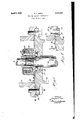
- FIG. 1 shows the device in section.
- Fig. 2 is a partial view of a modification.
- a compressor casing 10 and a motor casing 12 the .latter having a transverse wall 14 which forms a partition between the casings.
- the wall 14 is apertured and thru the aperture projects a shaft 16, one of whose ends is connected to the com pressor unit within the casing 10 and the other of which is connected to the motor unit within the casing 12.
- the ends of the shaft are mounted in bearings (not shown) andv the shaft is. sealed to the transverse wall in such a manner that communication of the fluid from casing 10 to casing 12 is prevented and such sealing means will now be specifically described.
- a cupped plate 20 Secured to the transverse wall .14 is a cupped plate 20 to which is secured one end of an expanslble and contractible bellows 22, the other end of the bellows being secured to the non-rotating ring 24, which is gen erally of anti-friction metal.
- the ring is provided with an annular edge 26 which engages a ring 28 forming one of the races of an anti-friction bearing, the other race comprising a ring 30 which is secured to the transverse wall 14 by means of a press fit, or the like.
- a coil spring 32 Disposed within the cupped plate 20 is a coil spring 32 which biases or orces the ring 24 into sealing engagement with the ring 28 as the latter rotates with the shaft 16.
- an effective seal which at the same time includes an anti-friction bearing ring us one of its elements, is provided and the.construction efficiently carries out its sealing function without minimizing the effect of the anti-friction bearing.
- a second feature of the invention is a novel seal between the casing parts, such seal serving to prevent fluid from escaping from the compressor 10 to the motor casing 12 or into the atmosphere, and such seal also serving as a means to insure the alignment of the shaft with respect to the casing.
- seal serving to prevent fluid from escaping from the compressor 10 to the motor casing 12 or into the atmosphere, and such seal also serving as a means to insure the alignment of the shaft with respect to the casing.
- the casing 10 is provided with a groove 42 having a gasket 44 therein, the gasket abutting the edge of the cupped plate 20, which is thus clamped between the gasket 44 and the transverse wall 14.
- the casings have abutting annular surfaces 44 and 46 which are accurately surfaced, machined, and ground, so as to be in perfect alignment with the shaft hearing surfaces and especially with the surfaces which support the race 30 of the anti-friction bearing in the transverse Wall 14.
- the casing parts are secured to each other by means of annularly spaced bolts 48.
- Fig. 2 there is shown a construction wherein the casings 50 and 52 are sealed and aligned with respect to each other by means of an annular rib 54 one of them being disposed on a gasket 56 in an annular groove 58 of the other, there being the usual accurately surfaced, machined and ground, engaging surfaces 60 and 62, thru which bolts may be passed, there being bolt holes 64 for this purose.
- the seal also serves to align the shaft with respect to the casings by aligning the casings with respect to each other, but the cupped plate 20 is not clamped between the casings as it is in the construction of Fig. 1.
- a combined seal and bearing construction for a casing having an apertured transverse wall thru which a rotating shaft projects comprising a cupped plate secured and sealed to said wall and having an aperture thru which said shaft projects, an anti-friction bearing surroundin said shaft and having a ring fixed to and rotating with said shaft, a non-rotating ring in the cup of said plate, an expansible bellows having its ends sealingly secured to said non-rotating ring and to said plate, and a coiled compression spring in said bellows and tending to expand the latter so as to bias said non-rotating ring into sealing engagement with said rotating
- a combined seal and bearing construction for a casing having an apertured transverse wall thru which a rotating shaft projects comprising a cupped plate secured and sealed to said wall and having an aperture thru which said shaft projects, an anti-friction bearing surrounding said shaft and having a ring fixed to and rotating with said shaft, a non-rotating ring in the cup of said plate, an expansible bellows having its ends sealingly secured to said non
- a combined seal and bearing construction for a casing having an apertured transverse wall thru which a rotating shaft projects comprising a cupped plate secured and sealed to said wall and having an aperture thru which said shaft projects, an anti-friction bearing surrounding said shaft and having a ring fixed to and rotating with said shaft, a non-rotating ring in the cup of said plate, an expansible bellows having its ends sealingly secured to saidnon-rotatingring and to said plate, and a coiled compression spring in said bellows and tending to expand the latter so as to bias said non-rotating ring into sealin engagement with said rotating ring, one 0 said rings having an annular sharp edge which engagesthe adjacent surface of the other ring.
- a combined seal and bearing construc-' tion for a casing having an apertured transverse wall thru which a rotating shaft projects comprising a cupped plate secured and sealed to said wall and having an aperture thru which said shaft projects, an anti-friction bearing surrounding said shaft and having a ring fixed to and rotating with said shaft, 21 non-rotating ring in the cup of said plate, an expansible bellows having its ends sealingly secured to said non-rotating ring and to said plate, and a coiled compression spring in said bellows and tending to expand the latter so as to bias said non-rotating ring into sealing engagement with said rotating ring, said anti-friction bearing being of the double-race type, wherein one race is secured to the casing wall, and the other forms the above mentioned rotating ring, one of said rings having an annular sharp edge which engages the adjacent surface of the other ring.
- Acombined seal and bearing construction including a casing-like part having an apertured transverse wall, a rotating shaft projecting thru the aperture of said wall, a
- said means including a plurality of annularly spaced bolts adapted to draw annular portions of the casing-like parts to each other, the annular portions having 00- operating, accurately formed, planar surfaces adapted to abut each other, one of the portions having an annular groove in which is disposed an annular gasket, the other of the portions having an annular raised portion seated in said groove and on said gasket, and adapted to compressthe latter.
- a combined seal and bearing construction including a casing-like part having an apertured transverse wall, a-rotating shaft projecting thru the aperture of said wall, a
- the shaft bearing in said aperture, a second casing-like part, and means for securing and sealing said casing-like parts to each other, the shaft bearing including a rotatin ring, the wall being provided with a on pe plate secured and sealed thereto, and aving an aperture thru which said shaft projects, a non-rotating ring in the cup of said cupped plate, an expansible bellows having its ends sealingly secured to said non-rotating ring and to the plate, and a coiled compression spring in said bellows and tending to expand the latter so as to bias said non-rotating ring into sealing engagement with said rotating ring.
- a combined seal and bearing construction including a casing-like part havin an apertured transverse wall, a rotating s aft projecting thru the aperture of said wall, a shaft bearing in said aperture, a second casing-like part, and means for securing and sealing said casing-like parts to each other in such a fashion that the ali ment of the shaft with respect to the casmg-like parts is maintained, said means including a Inrality of annularly spaced bolts adapte to draw annular portions of the casing-like parts to each other, the annular portions having cooperating, accurately formed, planar surfaces adapted to abut each other, one of the portions having an annular groove in which is disposed an annular gasket, the other of the portions having an annular raised portion seated in said groove and on said gasket, and adapted to compress the latter, the shaft bearing including a rotating ring, the wall being provided with a cupped plate secured and sealed thereto, and having an aperture thru which said shaft prog'ects, a non
Landscapes
- Engineering & Computer Science (AREA)
- General Engineering & Computer Science (AREA)
- Mechanical Engineering (AREA)
- Mechanical Sealing (AREA)
Description
7 SEAL AND BEARING CONSTRUCTION Filed March 2, 1931 INVENTOR @244 T M Y AITOR'NEY Patented Apr. 5, 1932 UNITED STATES PATENT OFFICE RUSSELL '1. SMITH, OF GZREEN'V'ILLE, MICHIGAN, ASSIGNOR 'IO GIBSON REFRIGERATOR COMPANY, 01' GREENVILLE, MICHIGAN, A CORPORATION OF MICHIGAN SEAL AND BEARING oons'rnuorron Application filed. March 2, 13131. Serial R0. 519,479.
This invention relates to seal and bearing constructions.
It is the practice at present, in refrigerator design, to connect two casings to each other, one of them being a compressor casing and the other being a motor casings One of the casings is generally provided with a transverse wall thru which projects a shaft common to the motor and to the compressor. The shaft, at its ends, is mounted in the motor and in the compressor and at an intermediate point, is sealed to the transverse Wall so that fluid communication between the motor casing and the compressor casing is prevented.
Further, it has been found desirable to support the shaft at points other than in the motor and compressor casings and the transverse wall thru which the shaft projects forms an ideal location for the shaft support or hearing.
An object of this invention, therefore, is a seal and bearing connection for a shaft which has ends in two relatively connected casings, one ofthe casings having a transverse wall in which the shaft is supported and to which the shaft is sealed.
A, further object is a novel form of seal between the casings above mentioned which is so constructed as to insure the alignment of the casin walls with the shaft.
Still furt er objects will readily occur to those skilled in the art upon reference to the following description and the accompanying drawings in which Fig. 1 shows the device in section.
Fig. 2 is a partial view of a modification.
Referring to the drawings, and more particularly to Fig. 1, it will be seen that there has been provided a compressor casing 10 and a motor casing 12, the .latter having a transverse wall 14 which forms a partition between the casings. The wall 14 is apertured and thru the aperture projects a shaft 16, one of whose ends is connected to the com pressor unit within the casing 10 and the other of which is connected to the motor unit within the casing 12. The ends of the shaft are mounted in bearings (not shown) andv the shaft is. sealed to the transverse wall in such a manner that communication of the fluid from casing 10 to casing 12 is prevented and such sealing means will now be specifically described.
Secured to the transverse wall .14 is a cupped plate 20 to which is secured one end of an expanslble and contractible bellows 22, the other end of the bellows being secured to the non-rotating ring 24, which is gen erally of anti-friction metal. The ring is provided with an annular edge 26 which engages a ring 28 forming one of the races of an anti-friction bearing, the other race comprising a ring 30 which is secured to the transverse wall 14 by means of a press fit, or the like. Disposed within the cupped plate 20 is a coil spring 32 which biases or orces the ring 24 into sealing engagement with the ring 28 as the latter rotates with the shaft 16.
It will be seen that an effective seal, which at the same time includes an anti-friction bearing ring us one of its elements, is provided and the.construction efficiently carries out its sealing function without minimizing the effect of the anti-friction bearing.
A second feature of the invention is a novel seal between the casing parts, such seal serving to prevent fluid from escaping from the compressor 10 to the motor casing 12 or into the atmosphere, and such seal also serving as a means to insure the alignment of the shaft with respect to the casing. Such means will now be described specifically.
The casing 10 is provided with a groove 42 having a gasket 44 therein, the gasket abutting the edge of the cupped plate 20, which is thus clamped between the gasket 44 and the transverse wall 14. The casings have abutting annular surfaces 44 and 46 which are accurately surfaced, machined, and ground, so as to be in perfect alignment with the shaft hearing surfaces and especially with the surfaces which support the race 30 of the anti-friction bearing in the transverse Wall 14. The casing parts are secured to each other by means of annularly spaced bolts 48.
When the casings are to be assembled with the shaft in place, the casings are brought together so that the edge of plate 20 and the gasket 44 are clamped between the casing 10 IOU and the transverse wall 14. The bolts 48 are tightened until surfaces 44-46 engage each other, during which time the gasket 44 is being compressed. Since surfaces 44-46 are accurately surfaced, the alignment of the casings and of the shaft will not depend upon the degree of compression of the gasket 44. In other words, casing 10 will be accurately positioned with respect to casing 12, regardless of the gasket 44. In this manner the casings are aligned with respect to each other and accordingly their bearings are accurately located with respect to one another.
In Fig. 2 there is shown a construction wherein the casings 50 and 52 are sealed and aligned with respect to each other by means of an annular rib 54 one of them being disposed on a gasket 56 in an annular groove 58 of the other, there being the usual accurately surfaced, machined and ground, engaging surfaces 60 and 62, thru which bolts may be passed, there being bolt holes 64 for this purose. p In this construction, the seal also serves to align the shaft with respect to the casings by aligning the casings with respect to each other, but the cupped plate 20 is not clamped between the casings as it is in the construction of Fig. 1.
Now having described the invention and the preferred embodiment thereof, it is to be understood that the said invention is to be limited, not to the specific detailsherein set forth, but only by the scope of the claims.
lVhat I claim 1s:
1. A combined seal and bearing construction for a casing having an apertured transverse wall thru which a rotating shaft projects comprising a cupped plate secured and sealed to said wall and having an aperture thru which said shaft projects, an anti-friction bearing surroundin said shaft and having a ring fixed to and rotating with said shaft, a non-rotating ring in the cup of said plate, an expansible bellows having its ends sealingly secured to said non-rotating ring and to said plate, and a coiled compression spring in said bellows and tending to expand the latter so as to bias said non-rotating ring into sealing engagement with said rotating A combined seal and bearing construction for a casing having an apertured transverse wall thru which a rotating shaft projects comprising a cupped plate secured and sealed to said wall and having an aperture thru which said shaft projects, an anti-friction bearing surrounding said shaft and having a ring fixed to and rotating with said shaft, a non-rotating ring in the cup of said plate, an expansible bellows having its ends sealingly secured to said non-rotating ring and to said plate, and a coiled compression spring in said bellows and tending to expand the latter so as to bias said non-rotating ring tion for a casing having an apertured transverse wall thru which a rotating shaft projects comprising a cupped plate secured and sealed to said wall and having an aperture thru which said shaft projects, an anti-friction bearing surrounding said shaft and having a ring fixed to and rotating with said shaft, a non-rotating ringin the cup of said plate, an expansible bellows having its ends sealingly secured to said non-rotating ring and to said plate, and a coiled compression spring in said bellows and tending to expand the latter so as to bias said non-rotating ring into sealing engagement with said rotating ring, said anti-friction bearing being of the double-race ball type, wherein one race is secured to the casing wall, and the other forms the above mentioned rotating ring.
4; A combined seal and bearing construction for a casing having an apertured transverse wall thru which a rotating shaft projects comprising a cupped plate secured and sealed to said wall and having an aperture thru which said shaft projects, an anti-friction bearing surrounding said shaft and having a ring fixed to and rotating with said shaft, a non-rotating ring in the cup of said plate, an expansible bellows having its ends sealingly secured to saidnon-rotatingring and to said plate, and a coiled compression spring in said bellows and tending to expand the latter so as to bias said non-rotating ring into sealin engagement with said rotating ring, one 0 said rings having an annular sharp edge which engagesthe adjacent surface of the other ring.
5. A combined seal and bearing construc-' tion for a casing having an apertured transverse wall thru which a rotating shaft projects, comprising a cupped plate secured and sealed to said wall and having an aperture thru which said shaft projects, an anti-friction bearing surrounding said shaft and having a ring fixed to and rotating with said shaft, 21 non-rotating ring in the cup of said plate, an expansible bellows having its ends sealingly secured to said non-rotating ring and to said plate, and a coiled compression spring in said bellows and tending to expand the latter so as to bias said non-rotating ring into sealing engagement with said rotating ring, said anti-friction bearing being of the double-race type, wherein one race is secured to the casing wall, and the other forms the above mentioned rotating ring, one of said rings having an annular sharp edge which engages the adjacent surface of the other ring.
6. Acombined seal and bearing construction including a casing-like part having an apertured transverse wall, a rotating shaft projecting thru the aperture of said wall, a
shaft bearing in said aperture, a second casing-like part, and means for securing and sealing said casing-like parts to each other, in such a fashion that the alignment of the shaft with respect to the casing-like parts is maintained, said means including a plurality of annularly spaced bolts adapted to draw annular portions of the casing-like parts to each other, the annular portions having 00- operating, accurately formed, planar surfaces adapted to abut each other, one of the portions having an annular groove in which is disposed an annular gasket, the other of the portions having an annular raised portion seated in said groove and on said gasket, and adapted to compressthe latter.
7. A combined seal and bearing construction including a casing-like part having an apertured transverse wall, a-rotating shaft projecting thru the aperture of said wall, a
shaft bearing in said aperture, a second casing-like part, and means for securing and sealing said casing-like parts to each other, the shaft bearing including a rotatin ring, the wall being provided with a on pe plate secured and sealed thereto, and aving an aperture thru which said shaft projects, a non-rotating ring in the cup of said cupped plate, an expansible bellows having its ends sealingly secured to said non-rotating ring and to the plate, and a coiled compression spring in said bellows and tending to expand the latter so as to bias said non-rotating ring into sealing engagement with said rotating ring.
8. A combined seal and bearing construction including a casing-like part havin an apertured transverse wall, a rotating s aft projecting thru the aperture of said wall, a shaft bearing in said aperture, a second casing-like part, and means for securing and sealing said casing-like parts to each other in such a fashion that the ali ment of the shaft with respect to the casmg-like parts is maintained, said means including a Inrality of annularly spaced bolts adapte to draw annular portions of the casing-like parts to each other, the annular portions having cooperating, accurately formed, planar surfaces adapted to abut each other, one of the portions having an annular groove in which is disposed an annular gasket, the other of the portions having an annular raised portion seated in said groove and on said gasket, and adapted to compress the latter, the shaft bearing including a rotating ring, the wall being provided with a cupped plate secured and sealed thereto, and having an aperture thru which said shaft prog'ects, a non-rotating ring in the cup of said plate, an expansible bellows having its ends sealingly secured to said non-rotating ring to the plate, and a coiled compression spring in said bellows and tending to expand the latter so as to bias said non-rotating ring into sealing en 7 tion.
RUSSELL T. SMITH.
Priority Applications (1)
| Application Number | Priority Date | Filing Date | Title |
|---|---|---|---|
| US519479A US1852681A (en) | 1931-03-02 | 1931-03-02 | Seal and bearing construction |
Applications Claiming Priority (1)
| Application Number | Priority Date | Filing Date | Title |
|---|---|---|---|
| US519479A US1852681A (en) | 1931-03-02 | 1931-03-02 | Seal and bearing construction |
Publications (1)
| Publication Number | Publication Date |
|---|---|
| US1852681A true US1852681A (en) | 1932-04-05 |
Family
ID=24068475
Family Applications (1)
| Application Number | Title | Priority Date | Filing Date |
|---|---|---|---|
| US519479A Expired - Lifetime US1852681A (en) | 1931-03-02 | 1931-03-02 | Seal and bearing construction |
Country Status (1)
| Country | Link |
|---|---|
| US (1) | US1852681A (en) |
-
1931
- 1931-03-02 US US519479A patent/US1852681A/en not_active Expired - Lifetime
Similar Documents
| Publication | Publication Date | Title |
|---|---|---|
| US4365816A (en) | Self-damping bellows seal assembly | |
| US2998987A (en) | Teflon lip seal | |
| US2742306A (en) | Seal assembly | |
| US2447663A (en) | Fluid seal | |
| US2676041A (en) | Packing for rotatable surfaces | |
| US3015504A (en) | Temperature compensated seal | |
| US2393260A (en) | Shaft seal | |
| US2395359A (en) | Seal | |
| US2393779A (en) | Sealing structure | |
| US1852681A (en) | Seal and bearing construction | |
| US2322867A (en) | Seal | |
| US3178191A (en) | Sealing structure | |
| US2283022A (en) | Lubricant seal for bearings | |
| US4094394A (en) | Clutch throw-out device | |
| US2978264A (en) | Seal | |
| US2211454A (en) | Piston packing | |
| US1900849A (en) | Seal | |
| US2277196A (en) | Packing gland construction | |
| US3001807A (en) | Sealing devices between a rotating part and a fixed part | |
| US1825918A (en) | Shaft seal | |
| US2433839A (en) | Shaft seal | |
| US1780248A (en) | Journal-bearing seal | |
| US2558970A (en) | Seal for rotary fuel pumps | |
| US2444714A (en) | Package-type seal | |
| US2559963A (en) | Bearing seal |