US1852668A - Mechanical hammer - Google Patents
Mechanical hammer Download PDFInfo
- Publication number
- US1852668A US1852668A US461815A US46181530A US1852668A US 1852668 A US1852668 A US 1852668A US 461815 A US461815 A US 461815A US 46181530 A US46181530 A US 46181530A US 1852668 A US1852668 A US 1852668A
- Authority
- US
- United States
- Prior art keywords
- rotor
- striker block
- striker
- block
- hammer
- Prior art date
- Legal status (The legal status is an assumption and is not a legal conclusion. Google has not performed a legal analysis and makes no representation as to the accuracy of the status listed.)
- Expired - Lifetime
Links
Images

Classifications
-
- B—PERFORMING OPERATIONS; TRANSPORTING
- B25—HAND TOOLS; PORTABLE POWER-DRIVEN TOOLS; MANIPULATORS
- B25D—PERCUSSIVE TOOLS
- B25D11/00—Portable percussive tools with electromotor or other motor drive
- B25D11/06—Means for driving the impulse member
- B25D11/066—Means for driving the impulse member using centrifugal or rotary impact elements
- B25D11/068—Means for driving the impulse member using centrifugal or rotary impact elements in which the tool bit or anvil is hit by a rotary impulse member
Definitions
- Patent 1,770,656 granted tome July 15, 1930, where a locking mechanism is inserted between the rotor and the striker block, which 7 mechanism after each stroke locks the striker block to the rotor, the violent recoil impacts of the striker block on the rotor causes the locking mechanism to be exposed to heavy strains, which may mean a danger of breaking the lock.
- the present invention consists in the provision, in connection with the casing enclosing the rotor and providing bearings for the same, of an arm which for each blow of strik- A er block against the tool is automatically brought into such a position that it will be hit by the striker block when the latter rebounds from the tool, so that the kinetic energy of the striker block produced by the recoil will be transm mitted by way of the said arm to the stationary casing enclosing the hammer, while the rotor remains unaffected.
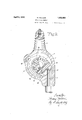
- FIG. 1 shows a section of a mechanical hammer, of the kind specified in said Letters Patent, at right angles to the axis of rotation of the rotor, and with the rotor in the position in which the locking mechanism between the rotor and the striker block is automatically released,
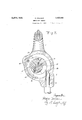
- Fig. 2 a corresponding view of the hammer in the position where the striker block, after having been swung out from the rotor, strikes the tool
- Fig. 3 a viewofthe'hammer at the moment when the striker block, after having struck the tool and after rebounding fromthelatter
- The-casing 1 enclosing the hammer is fitted with a handle 2 and has a bore 3, in which there may be inserted a tool 4, for instance achisel, a button-set or the like.
- the two side walls of the casing are fitted with-ballbearings 5, Fig. 2, for a shaft supporting the rotor 6.
- the latter is fitted with a pin lO-parallel to the shaft of the rotor and supporting the striker block 11, which-is fitted with a milled recess-38 one wall 34 of which forms a hammer face by means of which'the-striker block hits the tool 4 once for every revolution of the rotor 6-.
- the casing 1 is fitted with bearings for a pin 41 parallel to'the shaft of the'rotor and serving as pivot for'an arm 42.
- the arm 42 is integral with another arm 43, and the two armstogether have the shape of a semicircle engaging the rotor 6-with the striker block 11.
- the pin 41 may be resilient, or'it .may be rigid and be journaled in resiliently disposed bearings in the hammer casing l.
- the arm 42 is loaded by-means'of aspring pressing it inward in the direction of the rotor shaft, thenthearm 43 maybe. dispensed with, but a spring will act less reliably and bemore exposed-to fracture.
- the arms42 and 43 will further cause-the striker block 1-1,when the rotor is runnin and the tool 4 has beenremoved, to be turne automatically towards the rotor into *the position shownin Fig. 1 where thelockbinds it to the rotor, when. the automaticireleasing mechanism ofthe lock has been set out. of operation.
- the drawback isavoided that the rotormight revolvewithprojecting striker block when the. tool 4 has been removed.
- the invention may be used in otherzconstructions than the one shown on: the drawings, and it may'be mentioned especially'that the arm 42,v the stop' or the like which the striker block. hits. after having rebounded from the'tool may be 0t any shape'suited to the purpose, when only itis arrangedlin such a manner that the impact from the striker block willi be transmitted: therethroughl to the stationary casing of the hammer'andi not to the rotor.
- a mechanical hammer comprising a casing, a revoluble body, a striker block pivotally connected to said body and arranged under the influence of centrifugal forcetobe flung against atoolat every revolution of said body, an arm pivotally disposed about a pinwith hearings in the casingeocentrio to the axis of rotation of the-revoluble body and adapted to absorb tlie impact from-the striker block, when thelatt'er rebounds' from impact on thetool, soth'at this'impa'ct is transmitted to the casing by way of the said arm.
- a mechanism hammer comprising. a casing, a revoluble body, a striker block pivotaily connected to said body and arranged under the. influence of centrifugal
Landscapes
- Engineering & Computer Science (AREA)
- Mechanical Engineering (AREA)
- Percussive Tools And Related Accessories (AREA)
Description
Filed June 17, 1930 5 Sheets-Sheet l Tigi April 5, 1932. NlELsEN 1,852,668
' MECHANICAL HAMMER Filed June 17, 1950 5 Sheets-Sheet 2 Patented Apr. 5, 1932 PATENT OFFICE HERMAN NIELSEN, OF FREDERIKSBERG, BY COPENHAGEN, DENMARK MECHANICAL HAMMER Application filed June 17, 1930, Serial No. 461,815, and in Germany February 24, 1930.
Mechanical hammers of the kind bywhich one or more striker blocks are suspended from a rapidly rotating member, and are flung outward by centrifugal force and thereby strike a'tool, are subject to objections in that the striker block, after hitting the tool is repelled therefrom, and the recoil action from the impact is thereby taken up by the V rotary member supporting the striker block.
1 The motion of this member, Which in the following will be referred to as the rotor, is retarded by the striker blockv rebounding from the tool, as the rotor has to absorb the kinetic energy of the rebounding striker block, and then has to accelerate the striker block again,
so that the latter acquires the same speed forward as the rotor itself. At the moment when the rotor is hit by the rebounding striker block its rotary speed is reduced consider- 7 ably, and the rotor may even be stopped for a moment or forced to rotate backward for some short distance, until the return motion of the striker block has been stopped, whereafter the rotor once more rotates forward.
Especially if therotor is connected to the driving-motor'by a flexible shaft the effectof the recoil of the striker block will be considerable. The regular recoil impacts of the striker block against the rotor cause the latao ter to move so irregularly that the flexible 40 be the case, if these recoil blows did not occur. It has been attempted to avoid or reduce the effect of the recoil blows of the striker block by inserting, between the rotor and the striker block, a shock absorber, for instance in'shape of a chamber in which the atmospheric air is compressed by action of the striker block, but devices of this kind increase the generation of heat and have therefore not come into common use in practice. m
In hammers of the kind described in U. S.
A. Patent 1,770,656 granted tome July 15, 1930, where a locking mechanism is inserted between the rotor and the striker block, which 7 mechanism after each stroke locks the striker block to the rotor, the violent recoil impacts of the striker block on the rotor causes the locking mechanism to be exposed to heavy strains, which may mean a danger of breaking the lock.
The present invention consists in the provision, in connection with the casing enclosing the rotor and providing bearings for the same, of an arm which for each blow of strik- A er block against the tool is automatically brought into such a position that it will be hit by the striker block when the latter rebounds from the tool, so that the kinetic energy of the striker block produced by the recoil will be transm mitted by way of the said arm to the stationary casing enclosing the hammer, while the rotor remains unaffected. After the striker block, during its return motion, has struck thesaid arm the recoil action from this last impact will impart to the striker block a motion forward in the direction of rotation of the rotor, and as the rotor reaches forward to the striker block at the very moment when the latter strikes the said arms, the locking of the striker block to the rotor will be efifected easily and without any hindrance. The rotor and the flexible shaft will therefore not have to take up the recoil blow from the striker block and, consequently, the hammer will be worn less and heated less, and its blowing effect measured relatively to the consumption of power will be greater, because the motion of the rotor will so be more uniform and will not be counteracted by the recoil of the striker block.
One construction of the invention is illustrated on the drawings, where 5 Fig. 1 shows a section of a mechanical hammer, of the kind specified in said Letters Patent, at right angles to the axis of rotation of the rotor, and with the rotor in the position in which the locking mechanism between the rotor and the striker block is automatically released,
Fig. 2 a corresponding view of the hammer in the position where the striker block, after having been swung out from the rotor, strikes the tool, and
Fig. 3 a viewofthe'hammer at the moment when the striker block, after having struck the tool and after rebounding fromthelatter,
hits the arm disposed in connection with the hammer casing and, thus, instead of the rotorv receives the injurious blow from the striker block.
The-casing 1 enclosing the hammer is fitted with a handle 2 and has a bore 3, in which there may be inserted a tool 4, for instance achisel, a button-set or the like. The two side walls of the casing are fitted with-ballbearings 5, Fig. 2, for a shaft supporting the rotor 6. The latter is fitted with a pin lO-parallel to the shaft of the rotor and supporting the striker block 11, which-is fitted with a milled recess-38 one wall 34 of which forms a hammer face by means of which'the-striker block hits the tool 4 once for every revolution of the rotor 6-.
Between the rotor G-and-the striker blookll there is inserted a locking mechanism, which is not shown on the drawings and the construction of whichis otherwise irrelevant to the present invention. I The casing 1 is fitted with bearings for a pin 41 parallel to'the shaft of the'rotor and serving as pivot for'an arm 42. The arm 42 is integral with another arm 43, and the two armstogether have the shape of a semicircle engaging the rotor 6-with the striker block 11.
When the above mentioned members are in the-position shown in Fig. 1, and the striker block 11' is locked to the rotor 6, then the latter and the striker block can'freely rotate without the interconnected arms 42 and 43.
being moved relatively to the pin 41. If, however, in the position shown in Fig. 1 the lock binding the striker block 11 to the rotor 6 is released, then'the striker block while'actuated by centrifugal force will be flung out into striking position and immediately'thereafter hit the tool 4, as shown in Fig. 2. About simultaneously the striker'block, as shown in Fig. 2, strikes the end of the arm 43 and, thereby, turns the arm 42 inward towards the axis of rotation ofthe rotor. In consequence hereof the striker block, when rebounding from impact. on the tool 4, asshown in Fig. 3,
will hit the/end of the-arm42 which absorbs and annihilates the impact from the striker block, without the latter hitting the rotor 6. Simultaneously the striker block is again locked automatically to the rotor 6, and it participates then in the rotation of the latter, without being flung out by centrifugal force, until the lock between rotor and striking block is released again, which occurs when the rotor has once more reached the position shown in Fig. 1.
In order to mitigate the violent impact between the striker block 11 and the arm 43 the pin 41 may be resilient, or'it .may be rigid and be journaled in resiliently disposed bearings in the hammer casing l. Thereby the further advantage is attained that the striker block, whenever it hits the end of the arm 42, will receive a push forward in the direction of motion of the rotor, -so-that the latter will not be charged with'the work of accelerating the striker block;
If the arm 42 is loaded by-means'of aspring pressing it inward in the direction of the rotor shaft, thenthearm 43 maybe. dispensed with, but a spring will act less reliably and bemore exposed-to fracture.
The arms42 and 43 will further cause-the striker block 1-1,when the rotor is runnin and the tool 4 has beenremoved, to be turne automatically towards the rotor into *the position shownin Fig. 1 where thelockbinds it to the rotor, when. the automaticireleasing mechanism ofthe lock has been set out. of operation. Hereby the drawback isavoided that the rotormight revolvewithprojecting striker block when the. tool 4 has been removed.
The invention may be used in otherzconstructions than the one shown on: the drawings, and it may'be mentioned especially'that the arm 42,v the stop' or the like which the striker block. hits. after having rebounded from the'tool may be 0t any shape'suited to the purpose, when only itis arrangedlin such a manner that the impact from the striker block willi be transmitted: therethroughl to the stationary casing of the hammer'andi not to the rotor.
I claim:
1. A mechanical hammer comprising a casing, a revoluble body, a striker block pivotally connected to said body and arranged under the influence of centrifugal forcetobe flung against atoolat every revolution of said body, an arm pivotally disposed about a pinwith hearings in the casingeocentrio to the axis of rotation of the-revoluble body and adapted to absorb tlie impact from-the striker block, when thelatt'er rebounds' from impact on thetool, soth'at this'impa'ct is transmitted to the casing by way of the said arm.
2. A mechanism hammer" comprising. a casing, a revoluble body, a striker block pivotaily connected to said body and arranged under the. influence of centrifugal
Applications Claiming Priority (1)
| Application Number | Priority Date | Filing Date | Title |
|---|---|---|---|
| DE1852668X | 1930-02-24 |
Publications (1)
| Publication Number | Publication Date |
|---|---|
| US1852668A true US1852668A (en) | 1932-04-05 |
Family
ID=7746080
Family Applications (1)
| Application Number | Title | Priority Date | Filing Date |
|---|---|---|---|
| US461815A Expired - Lifetime US1852668A (en) | 1930-02-24 | 1930-06-17 | Mechanical hammer |
Country Status (1)
| Country | Link |
|---|---|
| US (1) | US1852668A (en) |
-
1930
- 1930-06-17 US US461815A patent/US1852668A/en not_active Expired - Lifetime
Similar Documents
| Publication | Publication Date | Title |
|---|---|---|
| US4287956A (en) | Impact wrench mechanism and pivot clutch | |
| JP2001508707A (en) | Rotary impact tool with involute hammer | |
| US2973071A (en) | Impact tool | |
| US1852668A (en) | Mechanical hammer | |
| US2802556A (en) | Impact hammer element | |
| US3486569A (en) | Impact mechanism | |
| US1770656A (en) | Mechanical hammer | |
| CN102689288A (en) | Automatic nailing gun | |
| US3212590A (en) | Impact wrench | |
| US1531549A (en) | Impact device | |
| US1898069A (en) | Hammer | |
| CN208679412U (en) | Plunger Rock Crusher | |
| CN220323019U (en) | Rebound instrument | |
| CN115284157B (en) | Ball mill for preparing electronic chemicals | |
| US1366850A (en) | Rotary hammer | |
| CN111947506B (en) | Trigger mechanism of a grenade launcher | |
| CN208099047U (en) | A kind of rotary type flexible, which is got rid of, makes forming device | |
| JPH01246080A (en) | Impact clutch | |
| US1824935A (en) | Percussion mechanism for tools | |
| CN116793878B (en) | Resiliometer | |
| US3262506A (en) | Power hammers | |
| US3474871A (en) | Power hammer | |
| SU136743A1 (en) | Rotary impact punching machine for opening the iron notch of the blast furnace | |
| US2025318A (en) | Vibrating device | |
| CN113503770B (en) | Firing device |