US1852657A - Machine for stacking lozenges - Google Patents
Machine for stacking lozenges Download PDFInfo
- Publication number
- US1852657A US1852657A US342390A US34239029A US1852657A US 1852657 A US1852657 A US 1852657A US 342390 A US342390 A US 342390A US 34239029 A US34239029 A US 34239029A US 1852657 A US1852657 A US 1852657A
- Authority
- US
- United States
- Prior art keywords
- discs
- shaft
- machine
- cross bar
- stack
- Prior art date
- Legal status (The legal status is an assumption and is not a legal conclusion. Google has not performed a legal analysis and makes no representation as to the accuracy of the status listed.)
- Expired - Lifetime
Links
- 239000007937 lozenge Substances 0.000 title description 9
- NJPPVKZQTLUDBO-UHFFFAOYSA-N novaluron Chemical compound C1=C(Cl)C(OC(F)(F)C(OC(F)(F)F)F)=CC=C1NC(=O)NC(=O)C1=C(F)C=CC=C1F NJPPVKZQTLUDBO-UHFFFAOYSA-N 0.000 description 2
- 238000010276 construction Methods 0.000 description 1
- 239000000463 material Substances 0.000 description 1
- 239000002184 metal Substances 0.000 description 1
- 238000005192 partition Methods 0.000 description 1
- 230000000452 restraining effect Effects 0.000 description 1
Images


Classifications
-
- B—PERFORMING OPERATIONS; TRANSPORTING
- B65—CONVEYING; PACKING; STORING; HANDLING THIN OR FILAMENTARY MATERIAL
- B65B—MACHINES, APPARATUS OR DEVICES FOR, OR METHODS OF, PACKAGING ARTICLES OR MATERIALS; UNPACKING
- B65B35/00—Supplying, feeding, arranging or orientating articles to be packaged
- B65B35/30—Arranging and feeding articles in groups
- B65B35/32—Arranging and feeding articles in groups by gravity
Definitions
- This invention consists of novel cooperating means for arranging a predetermined number of circular discs or lozenges of metal, confectionary or other materials into a cylinder or stack and transferring the stack to a wrapping belt, where it may be wrapped.
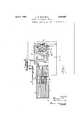
- Fig. 1 is a plan of this improved machine with a portion of the assembling and carrying devices omitted.
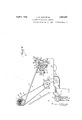
- Fig. 2 is a side elevation of the machine.
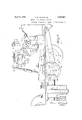
- Fig. 3 is a plan of the driving mechanism beneath the table which is broken away.
- Fig. 4 is a section on the line 44 of Fig. 1, on a larger scale.
- Fig. 5 is a partial longitudinal elevation showing a portion of the wrapping belt.
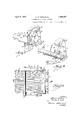
- Fig. 6 is a plan and Fig. 7 is a side elevation of the assembling mechanism.
- Fig. 8 is a section on the line 8-8 of Fig. 6.
- the claimed parts of the present machine include a rack or receiver for the discs to be wrapped embodying a series of converging troughs; a stack forming means and a transfer deviceor carrier which engages the two end discs of the stack to be wrapped'and, pressing the discs together, conveys the stack to a wrapping belt; and mechanism to cause the several devices to operate harmoniously and in order.
- any desired means may be employed to drive this shaft, an electric motor 4 being shown provided with a pulley 5 from which a belt 5a runs to the tight and loose pulleys 6 and 7 on the cross shaft, a shifter 8 for the belt being supplied.
- This cross shaft is provided with a worm (not shown) which meshes with a worm wheel 9 on the main shaft 10.
- a pulley 12 for the round belt 13 is also mounted on this cross shaft.
- a hand wheel 14 may be employedto turn the cross shaft but this is Serial No. 342,390.
- the receiver for the discs to be wrapped is shown in Figs. 1, 2, 6, 7 and 8 and consists of an inclined plate 16 supported by brackets 17 and 18 and having a series of ribs or partitions 19 on its upper surface, which ribs may be parallel at their upper ends but converge lower down.
- the discs A are dumped onto the upper end of the receiver and are caused to assume vertical positions in the spaces between these ribs by means of the rotating brushes 20 on the shaft 21 mounted in bearings 22 that are carried by the receiver, the pulley 23 on this shaft being driven by a belt 30 running to the pulley 31 on a small countershaft 32 (Fig. 2) and a second pulley 33 on this countershaft receives the belt 13.
- Fig. 5 shows how this link connects to a small lever 36, pivoted at 37 to a bracket 38 (Fig. 3) which extends down from a platform 35 on the table 1.
- This lever carries a roller 39 which runs on the cam 40 mounted on the shaft 41 carried in bearings 42 and 43, formed on the brackets 38 and 44.
- This shaft connects to the shaft 45 by means of the similar gears 46 and 47 and the latter shaft is driven from the main shaft 10 by means of similar gears 48 and 49.
- the bar 25 rises and permits a row of discs to run down until they are stopped by the swinging stop bar 50 which is carried by arms 52 mounted on the shaft 53 carried by the brackets 28.
- This stop bar is normally held in position by a spring 54 against the stops 55.
- the discs are supported by an apron 56 pivoted at 57 (Fig. 7), and held up by the spring 58.
- a stop 59 also on the bracket 28, limits the downward movement of the arm 26, cross bar 25 and of the fingers 24.
- Stack transfer The carrier to transfer the stack of discs from above the apron 56 to the wrapping belt is shown in Figs. 1, 2, 3, 4 and 5.
- a crank disc 60 on the end of the shaft 45 (Fig. 3) carries a crank pin 61 which extends through the lower end of the connecting rod 62, and the shaft 45 makes one turn for each cycle of the machine.
- the connecting rod 62 is attached to the pin 63 at the end of the crank arm 64 attached to the hub 65 which is rotatable on the shaft 66 carried by a pedestal 67.
- the friction is controlled by a bolt 72, spring 73 and nut 74 shown in Fig. 5.
- the brake on shaft 66 prevents rotation thereof when hub 65 is rotated but permits shaft 66 to rotate when hubs 74 are caused to rotate by the cross bar 79.
- the arms therefore, rest at the upper and lower ends of their movements while the cross bar 79 slides along the cam plates 76.
- the arms separate while at their lower position to release the stack of discs. They are separated sufliciently to pass the ends of the apron 56 and of the cross bar 50 when they move up, but when they come down, they simply swing these two supports out of the way, the arms 52 carrying the cross bar 50 being swung out, as shown in Fig. 2, and
- a receptacle for discs to be wrapped comprising an inclined surface provided with downwardly converging grooves in which the discs may run down, a vertically movable cross bar above the lower ends of said grooves and pivoted arms to support the bar, pins on the bar adapted to stop a transverse row of discs, a resiliently mounted bar and a resiliently mounted support adapted to receive a transverse row of said discs when the vertically movable cross bar with its pins is elevated, and a disc carrier comprising a pair of'swinging and laterally separable arms adapted to engage the outermost discs of each transverse row, press them together and pull them down from between the resiliently mounted bar and support.
- a receptacle for discs to be wrapped comprising an inclined surface provided with downwardly converging grooves in which the discs may run down, a vertically movable cross bar above the lower ends of said grooves and pivoted arms to supportthe bar, pins on the bar adapted to stop 5atransverse row of discs, a resiliently mounted bar and a resiliently mounted support adapted to receive a transverse row of said discs when the vertically movable cross bar with its pins is elevated.
- a receptacle for discs to be wrapped comprising an inclined surface provided with downwardly converging grooves in which the discs may run down
- a stop for said discs comprising a swinging cross bar above and adjacent to said surface, means to limit down ward movement of said cross bar, means to elevate said cross bar from its lowermost position
- a second stop comprising resiliently mounted jaws adapted to receive a stack of said discs after they have been released by the first stop.
- a receptacle for discs to be wrapped comprising an inclined surface provided with downwardly converging grooves in which the discs may run down, a stop for said discs comprising a swinging cross bar above and adjacent to said surface, means to limit downward movement of said cross bar, means to elevate said cross bar from its lowermost position, and a second stop comprising resiliently mounted jaws adapted to receive a stack of said discs after they have been released by the first stop, both of said jaws being pivoted to said receptacle.
- Means to transfer a stack of discs from a stack forming machine to a stack Wrapping machine comprising a shaft, a pair of hubs spaced along said shaft, arms carried by said hubs, a pair of cams on the inner faces of said hubs, and a cam bar intermediate said hubs and movable With respect thereto so as to cause the latter to slide along said shaft and to rotate With said shaft, as desired.
Landscapes
- Engineering & Computer Science (AREA)
- Mechanical Engineering (AREA)
- Specific Conveyance Elements (AREA)
Description
April 5, 1932. A. w. KATH ET AL MACHINE FOR STACKING LOZENGES Original Filed Jan. 11, 1926 6 Sheets-Sheet 1 IN VEN TOR-Y, 1-.) 165-7 3 April 5, 1932- A. w. KATH ET AL 1,852,657
MACHINE FOR STACKING LOZENGES Original Filed Jan. 11. 1926 6 heets-Sheet 2 April 5, 1932. A. w. KATH ET AL 1,852,557
MACHINE FOR STACKING LOZENGES Original Filed Jan. 11, 1926 6 h e shee 3 INVENTORJ, a l
A TTORNE A ril 5, 1932.
A w. KATH ET AL MACHINE FOR STACKING LOZENGES INVENTOR @JZ ATTORNEY.
Original Filed Jan. 11, 1926 6 Sheets-Sheet 4 April 5, 1932. KATH ET AL 3 1,852,657
MACHINE FOR STACKING LOZENGES Original Filed Jan. 11, 1926 6 SheetsSheet 5 INVENTORJ. I Jazz A TTORNEY.
April 5, 1932. A, w AT ET L 1,852,657
MACHINE FOR STACKING LOZENGES Original Filed Jan. 11, 1926 6 hee 6 IN VEN TORJ.
A TTORNEY.
Patented Apr. 5, 1932 UNITED STATES PATENT orrlcs ALFRED W. KATI-I AND BURTON W. SCOTT, OF DETROIT, MICHIGAN, ASSIGNORS TO ARTHUR COLTON COMPANY, 013 DETROIT, MICHIGAN, A CORPORATION OF MICH- IGAN MACHINE FOR STAGKING LOZENGES Original application filed January 11, 1926, Serial No. 80,449. Divided and this application filed February 25, 1929.
This invention consists of novel cooperating means for arranging a predetermined number of circular discs or lozenges of metal, confectionary or other materials into a cylinder or stack and transferring the stack to a wrapping belt, where it may be wrapped.
It also consists of the details of construction illustrated in the accompanying drawings and particularly pointed out in the claims.
In the accompanying drawings, Fig. 1 is a plan of this improved machine with a portion of the assembling and carrying devices omitted. Fig. 2 is a side elevation of the machine. Fig. 3 is a plan of the driving mechanism beneath the table which is broken away. Fig. 4 is a section on the line 44 of Fig. 1, on a larger scale. Fig. 5 is a partial longitudinal elevation showing a portion of the wrapping belt. Fig. 6 is a plan and Fig. 7 is a side elevation of the assembling mechanism. Fig. 8 is a section on the line 8-8 of Fig. 6.
Similar reference characters refer to like parts throughout the several views.
The claimed parts of the present machine include a rack or receiver for the discs to be wrapped embodying a series of converging troughs; a stack forming means and a transfer deviceor carrier which engages the two end discs of the stack to be wrapped'and, pressing the discs together, conveys the stack to a wrapping belt; and mechanism to cause the several devices to operate harmoniously and in order.
All of this mechanism is mounted on the top and on the lower side of the table 1 which may be supported on legs 2, and is shown to be driven by a cross shaft 3 (Fig.
Any desired means may be employed to drive this shaft, an electric motor 4 being shown provided with a pulley 5 from which a belt 5a runs to the tight and loose pulleys 6 and 7 on the cross shaft, a shifter 8 for the belt being supplied. This cross shaft is provided with a worm (not shown) which meshes with a worm wheel 9 on the main shaft 10. A pulley 12 for the round belt 13 is also mounted on this cross shaft. A hand wheel 14 may be employedto turn the cross shaft but this is Serial No. 342,390.
preferably normally disengaged by sliding.
it along the shaft to relieve the machine of the inertia of this wheel. The main shaft 10 makes one rotation for each operation of the machine. Stack forming The receiver for the discs to be wrapped is shown in Figs. 1, 2, 6, 7 and 8 and consists of an inclined plate 16 supported by brackets 17 and 18 and having a series of ribs or partitions 19 on its upper surface, which ribs may be parallel at their upper ends but converge lower down. The discs A are dumped onto the upper end of the receiver and are caused to assume vertical positions in the spaces between these ribs by means of the rotating brushes 20 on the shaft 21 mounted in bearings 22 that are carried by the receiver, the pulley 23 on this shaft being driven by a belt 30 running to the pulley 31 on a small countershaft 32 (Fig. 2) and a second pulley 33 on this countershaft receives the belt 13.
The discs fill the troughs between the ribs 19 and roll down until stopped by the spring held fingers 24 carried by the cross bar 25 mounted on the arms 26. These arms are pivoted on the shaft 27 mounted in the brackets 28 at the lower end of the receiver and are swung up and down by the link 29 (Fig. 7.) Fig. 5 shows how this link connects to a small lever 36, pivoted at 37 to a bracket 38 (Fig. 3) which extends down from a platform 35 on the table 1. This lever carries a roller 39 which runs on the cam 40 mounted on the shaft 41 carried in bearings 42 and 43, formed on the brackets 38 and 44. This shaft connects to the shaft 45 by means of the similar gears 46 and 47 and the latter shaft is driven from the main shaft 10 by means of similar gears 48 and 49. At each rotation of the main shaft therefore, the bar 25 rises and permits a row of discs to run down until they are stopped by the swinging stop bar 50 which is carried by arms 52 mounted on the shaft 53 carried by the brackets 28. This stop bar is normally held in position by a spring 54 against the stops 55. When against the stop bar the discs are supported by an apron 56 pivoted at 57 (Fig. 7), and held up by the spring 58. A stop 59, also on the bracket 28, limits the downward movement of the arm 26, cross bar 25 and of the fingers 24.
Stack transfer The carrier to transfer the stack of discs from above the apron 56 to the wrapping belt is shown in Figs. 1, 2, 3, 4 and 5. A crank disc 60 on the end of the shaft 45 (Fig. 3) carries a crank pin 61 which extends through the lower end of the connecting rod 62, and the shaft 45 makes one turn for each cycle of the machine. The connecting rod 62 is attached to the pin 63 at the end of the crank arm 64 attached to the hub 65 which is rotatable on the shaft 66 carried by a pedestal 67. A brake drum 68 on one end of this shaft, engaged by a band 69 mounted on the pin 70 carried by the pedestal 67, restrains but does not prevent absolutely the rotation of this shaft. The friction is controlled by a bolt 72, spring 73 and nut 74 shown in Fig. 5.
Slidable on but keyed to the shaft- 66 are the hubs 74 to which the arms 75 connect. Cam plates 76 are attached to the inner sides of these arms and end in lugs 77 and 78. A cross bar 79 slidable in and rotatable with the hub 65 has rounded ends engaging the cam plates 76 which are normally drawn toward each other by the spring shown in Fig. 1.
When the rod 62 moves down the cross bar 79 will move up, the brake restraining the shaft 66 from turning. Thus the cross bar 79 and the cam plates 76 will cause the arms 75 to separate along the shaft 66, when the cross bar reaches and abuts the lugs 77, the arms 75 will be swung up, while separated, until they reach the position shown in Fig. 8. The cross bar 79 then slides down the cam plates 76 and the arms 75 come together due to the spring 80, so as to grip a stack of discs. When the cross bar reaches the lugs 78 the arms 75 holding a stack of discs between them, will swing down to the position shown in Fig. 2, placing the stack of discs on the wrapping belt 84.
The brake on shaft 66 prevents rotation thereof when hub 65 is rotated but permits shaft 66 to rotate when hubs 74 are caused to rotate by the cross bar 79.
The arms, therefore, rest at the upper and lower ends of their movements while the cross bar 79 slides along the cam plates 76. The arms separate while at their lower position to release the stack of discs. They are separated sufliciently to pass the ends of the apron 56 and of the cross bar 50 when they move up, but when they come down, they simply swing these two supports out of the way, the arms 52 carrying the cross bar 50 being swung out, as shown in Fig. 2, and
the apron being swung down on its pivot 57 in a manner which will be obvious.
Detailed description of other parts of the machine are not being included herein, being included in the copending application, Serial No. 80,449, filed January 11, 1926, now Patent No. 1,709,984, of which the present application is a division.
Now having described the invention and the preferred forms of embodiment thereof, it is to be understood that the said invention is to be limited not to the specific details herein described and illustrated, but only by the scope of the claims which follow:
o claim 1. In a disc wrapping machine, the combination of a receptacle for discs to be wrapped comprising an inclined surface provided with downwardly converging grooves in which the discs may run down, a vertically movable cross bar above the lower ends of said grooves and pivoted arms to support the bar, pins on the bar adapted to stop a transverse row of discs, a resiliently mounted bar and a resiliently mounted support adapted to receive a transverse row of said discs when the vertically movable cross bar with its pins is elevated, and a disc carrier comprising a pair of'swinging and laterally separable arms adapted to engage the outermost discs of each transverse row, press them together and pull them down from between the resiliently mounted bar and support.
2. In a disc wrapping machine, the combination of a receptacle for discs to be wrapped comprising an inclined surface provided with downwardly converging grooves in which the discs may run down, a vertically movable cross bar above the lower ends of said grooves and pivoted arms to supportthe bar, pins on the bar adapted to stop 5atransverse row of discs, a resiliently mounted bar and a resiliently mounted support adapted to receive a transverse row of said discs when the vertically movable cross bar with its pins is elevated.
3. In a disc wrapping machine, the combination of a receptacle for discs to be wrapped comprising an inclined surface provided with downwardly converging grooves in which the discs may run down, a stop for said discs comprising a swinging cross bar above and adjacent to said surface, means to limit down ward movement of said cross bar, means to elevate said cross bar from its lowermost position, and a second stop comprising resiliently mounted jaws adapted to receive a stack of said discs after they have been released by the first stop.
4. In a disc wrapping machine, the combination of a receptacle for discs to be wrapped comprising an inclined surface provided with downwardly converging grooves in which the discs may run down, a stop for said discs comprising a swinging cross bar above and adjacent to said surface, means to limit downward movement of said cross bar, means to elevate said cross bar from its lowermost position, and a second stop comprising resiliently mounted jaws adapted to receive a stack of said discs after they have been released by the first stop, both of said jaws being pivoted to said receptacle.
5. Means to transfer a stack of discs from a stack forming machine to a stack Wrapping machine, comprising a shaft, a pair of hubs spaced along said shaft, arms carried by said hubs, a pair of cams on the inner faces of said hubs, and a cam bar intermediate said hubs and movable With respect thereto so as to cause the latter to slide along said shaft and to rotate With said shaft, as desired.
ALFRED W. KATH. BURTON W. SCOTT.
Priority Applications (1)
| Application Number | Priority Date | Filing Date | Title |
|---|---|---|---|
| US342390A US1852657A (en) | 1926-01-11 | 1929-02-25 | Machine for stacking lozenges |
Applications Claiming Priority (2)
| Application Number | Priority Date | Filing Date | Title |
|---|---|---|---|
| US80449A US1709984A (en) | 1926-01-11 | 1926-01-11 | Wrapping machine |
| US342390A US1852657A (en) | 1926-01-11 | 1929-02-25 | Machine for stacking lozenges |
Publications (1)
| Publication Number | Publication Date |
|---|---|
| US1852657A true US1852657A (en) | 1932-04-05 |
Family
ID=26763530
Family Applications (1)
| Application Number | Title | Priority Date | Filing Date |
|---|---|---|---|
| US342390A Expired - Lifetime US1852657A (en) | 1926-01-11 | 1929-02-25 | Machine for stacking lozenges |
Country Status (1)
| Country | Link |
|---|---|
| US (1) | US1852657A (en) |
-
1929
- 1929-02-25 US US342390A patent/US1852657A/en not_active Expired - Lifetime
Similar Documents
| Publication | Publication Date | Title |
|---|---|---|
| US3058604A (en) | Article treating machine and loadunload mechanism therefor | |
| US1490594A (en) | Veneer and rotary cut lumber stacker | |
| US2704177A (en) | Roll panning machine | |
| US2780340A (en) | Turning device | |
| US2667259A (en) | Sheet handling apparatus | |
| US1852657A (en) | Machine for stacking lozenges | |
| US1959327A (en) | Cup dropping machine | |
| US2442827A (en) | Bottle transferring apparatus | |
| US3052278A (en) | Devices for forming grooves in articles | |
| US2089385A (en) | Unstacking and transferring mechanism | |
| US1959656A (en) | Machine for rounding and backing books | |
| US3122241A (en) | Automatic packaging machine | |
| US2135805A (en) | Can stacking machine | |
| US3106315A (en) | Packaging apparatus | |
| US1801997A (en) | Machine for feeding biscuits and the like | |
| US1593882A (en) | Conveyer for driers | |
| US2057772A (en) | Machine for making pretzels | |
| US1117244A (en) | Stacking-machine. | |
| US2224510A (en) | Egg carton and egg filler assembling machine | |
| US1430628A (en) | Paring machine | |
| US1303599A (en) | salerno | |
| US3269568A (en) | Apparatus for unstacking pallets | |
| US2284575A (en) | Feeding machine for rolling mills | |
| US2354103A (en) | Can transfer apparatus and method | |
| US2116793A (en) | Can casing machine |