US1852656A - Altitude finder - Google Patents
Altitude finder Download PDFInfo
- Publication number
- US1852656A US1852656A US532896A US53289631A US1852656A US 1852656 A US1852656 A US 1852656A US 532896 A US532896 A US 532896A US 53289631 A US53289631 A US 53289631A US 1852656 A US1852656 A US 1852656A
- Authority
- US
- United States
- Prior art keywords
- scale
- altitude
- ring
- horizon
- globe
- Prior art date
- Legal status (The legal status is an assumption and is not a legal conclusion. Google has not performed a legal analysis and makes no representation as to the accuracy of the status listed.)
- Expired - Lifetime
Links
- 208000004067 Flatfoot Diseases 0.000 description 1
- 238000010276 construction Methods 0.000 description 1
Images
Classifications
-
- G—PHYSICS
- G09—EDUCATION; CRYPTOGRAPHY; DISPLAY; ADVERTISING; SEALS
- G09B—EDUCATIONAL OR DEMONSTRATION APPLIANCES; APPLIANCES FOR TEACHING, OR COMMUNICATING WITH, THE BLIND, DEAF OR MUTE; MODELS; PLANETARIA; GLOBES; MAPS; DIAGRAMS
- G09B27/00—Planetaria; Globes
- G09B27/06—Celestial globes
Definitions
- This invention relates to improvements in altitude and azimuth finders and, more especially, such a device adapted for use With a sphere or globe in a mounting including an horizon ring.
- My improved apparatus also -enables a user to 5nd the azimuth of a star or other body on a celestial globe or the longitude of a city or other place on a terrestrial globe (assuming the) axis of the terrestrial globe to be vertical
- My improved device is so constructed that it can be used in conjunction With the horizon ring so that it can be placed in any position with respect to the globe and supported in a substantially vertical plane passing through the center of the sphere. vWhen thus positioned, the altitude can be read on the scale and the position of the foot or base of the scale on the horizon ring Will shovv the azimuth.
- the scale in order to show the correct altitude and azimuth, the scale must lie in a vertical plane passing through the center of the sphere; and my improved scale is provided With a base adapted to be fitted on the horizon ring so that the scale can be ease ily and correctly placed.
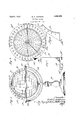
- Figure 1 is a vievv in side elevation
- Fig. 2 is a top plan view
- Fig. 3 is a fragmentary view of the scale in end elevation
- Fig. 4t is a similar view of the scale in side elevation.
- 10 indicates a celestial globe rotatably mounted in the meridian ring 11, which latter is rotatably sup- 1931.
- Numeral 13 indicates an ordinary supportrvvith a semicircular member 14 carrying the horizon ring 12.
- the horizon ring 12 is provided With a flat horizontal upper surface 12'L1 graduated or scaled, as indicated by 12".
- My improved' altitude and azimuth finder includes ⁇ an arc-shaped or quadrant scale 15 suitably graduated in degrees, as indicated by 16, from the base to the upper end. It is understood that the curvature of the scale corresponds to the curvature of the globe With which it is to be used. As here shown, the scale is preferably not quite a complete quadrant'. It may be, for example, only 85 long so that when the aXis of the globe is vertical, there will be room for the axle mounting 17.
- the scale 15 is provided With a base 18 having a flat lower surface 18a lying at right angles to the plane of the scale 15. Vhen this base 18 is placed on the horizon ring with the surface 18a fiat on the up.- per surface 12a of the horizon ring, it Will ensure that the scale l5 lies in a vertical plane, that is, a plane at right angles to the upper horizontal surface of the horizon ring. In order to position the scale accurately, the same must lie not only in a vertical plane, but in a vertical plane passing through the center of the sphere. rihe base 18 of the scale is accordingly provided With two depending members 18b adapted to be placed in contact With the outer circular edge 12c of the horizon ring.
- the members 18b are so arranged that When they are both in contact With such outer edge of the horizon ring, the scale 15 will lie in a vertical plane passing through a radius of the horizon ring and, consequently, passing through the center of the sphere. It is obvious that instead of providing two depending members 18", 18h, a single elongated one suitably curved or arc-ed to fit against the outer surface of the horizon ring could be used. In fact, the two pieces 18h, 18b may be considered as a single curved elongated member with the middle portion removed.
- Figs. 1 and 2 the scale is shown in position and it Will be seen that the altitude of a star can be read on the scale itself and the azimuth can be read on the scale on the upper surface of the horizon ring by noting the position of the foot of the vertical arc or scale 15. Y
- a relatively narrow arc-shaped member having a scale of substantially thereon, said member having a broad foot projecting substantially at right angles to its plane, said foot adapted to be fitted on the horizon ring of a sphere to prevent lateral tipping of said arc-shaped member.
- a device as claimed in claim 1 in which the foot is adapted to be fitted on the horizon ring to hold the arc-shaped member in a substantially vertical plane passing through the center of said ring.
- a device as claimed in claim 1 in which he foot is provided with a bottom iat surface adapted to be fitted on the. top of an horizon ring having a Hat upper surface.
- a relatively narrow arc-shaped member having a scale of substantially 90o thereon, said member having a broad flat foot pro* jecting substantially at right angles to its plane, said foot having a flat bottom surface adapted to rest on the top of an horizon ring having a iat upper surface and said foot h strings provided with a part or parts adapted to engage the outer edge of a curved horizon ring to hold the scale in a vertical plane passing through the center of such a ring.
Landscapes
- Physics & Mathematics (AREA)
- General Physics & Mathematics (AREA)
- Engineering & Computer Science (AREA)
- Astronomy & Astrophysics (AREA)
- Business, Economics & Management (AREA)
- Educational Administration (AREA)
- Educational Technology (AREA)
- Theoretical Computer Science (AREA)
- Instructional Devices (AREA)
Description
W. E. JOHNSON ALTITUDE FINDER April 5, 1932.
Filed April 25, 1931 Patented Apr. s, 1932 UNITE s Tar oFFplcE WILLIAM E. JOHNSON, OF CHICAGO, ILLINOIS, VASSIGNOR TO RAND MCNALLY & -COM- PANY, OF CHICAGG, ILLINOIS, A CORPORATION 0F ILLINOIS ALTITUDE FINDER Application led April 25,
This invention relates to improvements in altitude and azimuth finders and, more especially, such a device adapted for use With a sphere or globe in a mounting including an horizon ring.
Among the features of my invention is the provision of such a device enabling a user to find the altitude of a star or other body above the horizon on a celestial globe, or the latitude of a city or other place on a terrestrial globe (assuming the axis of the globe to be vertical). For the purpose of illustration, the globe here shown is a celestial globe.
My improved apparatus also -enables a user to 5nd the azimuth of a star or other body on a celestial globe or the longitude of a city or other place on a terrestrial globe (assuming the) axis of the terrestrial globe to be vertical My improved device is so constructed that it can be used in conjunction With the horizon ring so that it can be placed in any position with respect to the globe and supported in a substantially vertical plane passing through the center of the sphere. vWhen thus positioned, the altitude can be read on the scale and the position of the foot or base of the scale on the horizon ring Will shovv the azimuth.
It is obvious that in order to show the correct altitude and azimuth, the scale must lie in a vertical plane passing through the center of the sphere; and my improved scale is provided With a base adapted to be fitted on the horizon ring so that the scale can be ease ily and correctly placed.
Other features and advantages of my invention Will appear more fully as I proceed With my specification.
In that form of device embodying the features of my invention shown in the accom panying drawings- Figure 1 is a vievv in side elevation; Fig. 2 is a top plan view; Fig. 3 is a fragmentary view of the scale in end elevation; and Fig. 4t is a similar view of the scale in side elevation.
As shown in the drawings, 10 indicates a celestial globe rotatably mounted in the meridian ring 11, Which latter is rotatably sup- 1931. Serial No. 532,898.
ported in the horizon ring 12. Numeral 13 indicates an ordinary supportrvvith a semicircular member 14 carrying the horizon ring 12.
As here shown, the horizon ring 12 is provided With a flat horizontal upper surface 12'L1 graduated or scaled, as indicated by 12".
My improved' altitude and azimuth finder includes` an arc-shaped or quadrant scale 15 suitably graduated in degrees, as indicated by 16, from the base to the upper end. It is understood that the curvature of the scale corresponds to the curvature of the globe With which it is to be used. As here shown, the scale is preferably not quite a complete quadrant'. It may be, for example, only 85 long so that when the aXis of the globe is vertical, there will be room for the axle mounting 17.
As shown in F ig. 3, the scale 15 is provided With a base 18 having a flat lower surface 18a lying at right angles to the plane of the scale 15. Vhen this base 18 is placed on the horizon ring with the surface 18a fiat on the up.- per surface 12a of the horizon ring, it Will ensure that the scale l5 lies in a vertical plane, that is, a plane at right angles to the upper horizontal surface of the horizon ring. In order to position the scale accurately, the same must lie not only in a vertical plane, but in a vertical plane passing through the center of the sphere. rihe base 18 of the scale is accordingly provided With two depending members 18b adapted to be placed in contact With the outer circular edge 12c of the horizon ring. The members 18b are so arranged that When they are both in contact With such outer edge of the horizon ring, the scale 15 will lie in a vertical plane passing through a radius of the horizon ring and, consequently, passing through the center of the sphere. It is obvious that instead of providing two depending members 18", 18h, a single elongated one suitably curved or arc-ed to fit against the outer surface of the horizon ring could be used. In fact, the two pieces 18h, 18b may be considered as a single curved elongated member with the middle portion removed.
In Figs. 1 and 2, the scale is shown in position and it Will be seen that the altitude of a star can be read on the scale itself and the azimuth can be read on the scale on the upper surface of the horizon ring by noting the position of the foot of the vertical arc or scale 15. Y
While I have shown and described certain embodiments of my invention, it is to be understood that it is capable of many modications. Changes, therefore, in the construction and arrangement may be made Without departing from the spirit and scope of the invention as disclosed in the appended claims, in which it is my intention to claim all novelty inherent in my invention as broadly as permissible, in view of the prior art.
What I regard as new, and desire to secure by Letters Patent, is:
1. A relatively narrow arc-shaped member having a scale of substantially thereon, said member having a broad foot projecting substantially at right angles to its plane, said foot adapted to be fitted on the horizon ring of a sphere to prevent lateral tipping of said arc-shaped member.
2. A device as claimed in claim 1 in which the foot is adapted to be fitted on the horizon ring to hold the arc-shaped member in a substantially vertical plane passing through the center of said ring.
3. A device as claimed in claim 1 in which he foot is provided with a bottom iat surface adapted to be fitted on the. top of an horizon ring having a Hat upper surface.
4. A relatively narrow arc-shaped member having a scale of substantially 90o thereon, said member having a broad flat foot pro* jecting substantially at right angles to its plane, said foot having a flat bottom surface adapted to rest on the top of an horizon ring having a iat upper surface and said foot heilig provided with a part or parts adapted to engage the outer edge of a curved horizon ring to hold the scale in a vertical plane passing through the center of such a ring.
In witness` whereof, I have hereunto set my hand and seal, this 21 day of April, 1931.
WILLIAM E. JOHNSON.
Priority Applications (1)
| Application Number | Priority Date | Filing Date | Title |
|---|---|---|---|
| US532896A US1852656A (en) | 1931-04-25 | 1931-04-25 | Altitude finder |
Applications Claiming Priority (1)
| Application Number | Priority Date | Filing Date | Title |
|---|---|---|---|
| US532896A US1852656A (en) | 1931-04-25 | 1931-04-25 | Altitude finder |
Publications (1)
| Publication Number | Publication Date |
|---|---|
| US1852656A true US1852656A (en) | 1932-04-05 |
Family
ID=24123644
Family Applications (1)
| Application Number | Title | Priority Date | Filing Date |
|---|---|---|---|
| US532896A Expired - Lifetime US1852656A (en) | 1931-04-25 | 1931-04-25 | Altitude finder |
Country Status (1)
| Country | Link |
|---|---|
| US (1) | US1852656A (en) |
Cited By (1)
| Publication number | Priority date | Publication date | Assignee | Title |
|---|---|---|---|---|
| US4096646A (en) * | 1977-04-28 | 1978-06-27 | Solem Philip M | Device for identifying and locating a star in the heavens |
-
1931
- 1931-04-25 US US532896A patent/US1852656A/en not_active Expired - Lifetime
Cited By (1)
| Publication number | Priority date | Publication date | Assignee | Title |
|---|---|---|---|---|
| US4096646A (en) * | 1977-04-28 | 1978-06-27 | Solem Philip M | Device for identifying and locating a star in the heavens |
Similar Documents
| Publication | Publication Date | Title |
|---|---|---|
| US4438568A (en) | Recreational compass | |
| US1852656A (en) | Altitude finder | |
| US1873595A (en) | Star finder | |
| US3059339A (en) | Navigational device | |
| US2328517A (en) | Movable position finding devices, particularly course protractors | |
| US78133A (en) | Improvement in heuometebs | |
| US1354195A (en) | Combined compass and quadrant | |
| US3281961A (en) | Globe structure | |
| US1789439A (en) | Desk novelty | |
| US1216953A (en) | Magnetic compass. | |
| US248259A (en) | Terrestrial globes | |
| US1419604A (en) | Geographical globe | |
| US1498225A (en) | Globe mounting | |
| US3613249A (en) | Device for locating heavenly bodies | |
| US1777741A (en) | Desk set | |
| US1258160A (en) | Sun-dial and compass. | |
| US18931A (en) | Apparatus for illustrating conic sections and the lines of the globe | |
| US2765649A (en) | Device for determining deviation of magnetic compasses | |
| US1572528A (en) | Azimuth reader for magnetic compasses | |
| US1634289A (en) | Educational apparatus | |
| USRE22670E (en) | Astronomical instrument | |
| US2918725A (en) | Star clock | |
| US157586A (en) | Improvement im sum-dials | |
| US865597A (en) | Protractor. | |
| US1895834A (en) | Combination implement |