US1852653A - Engine starter - Google Patents
Engine starter Download PDFInfo
- Publication number
- US1852653A US1852653A US509157A US50915731A US1852653A US 1852653 A US1852653 A US 1852653A US 509157 A US509157 A US 509157A US 50915731 A US50915731 A US 50915731A US 1852653 A US1852653 A US 1852653A
- Authority
- US
- United States
- Prior art keywords
- pinion
- catch
- starter
- block
- motor
- Prior art date
- Legal status (The legal status is an assumption and is not a legal conclusion. Google has not performed a legal analysis and makes no representation as to the accuracy of the status listed.)
- Expired - Lifetime
Links
- 239000007858 starting material Substances 0.000 title description 53
- 230000007935 neutral effect Effects 0.000 description 11
- 238000002485 combustion reaction Methods 0.000 description 8
- 230000000994 depressogenic effect Effects 0.000 description 2
- 238000010276 construction Methods 0.000 description 1
- 210000005069 ears Anatomy 0.000 description 1
- 230000000266 injurious effect Effects 0.000 description 1
- 239000002184 metal Substances 0.000 description 1
Images
Classifications
-
- F—MECHANICAL ENGINEERING; LIGHTING; HEATING; WEAPONS; BLASTING
- F02—COMBUSTION ENGINES; HOT-GAS OR COMBUSTION-PRODUCT ENGINE PLANTS
- F02N—STARTING OF COMBUSTION ENGINES; STARTING AIDS FOR SUCH ENGINES, NOT OTHERWISE PROVIDED FOR
- F02N15/00—Other power-operated starting apparatus; Component parts, details, or accessories, not provided for in, or of interest apart from groups F02N5/00 - F02N13/00
- F02N15/02—Gearing between starting-engines and started engines; Engagement or disengagement thereof
- F02N15/04—Gearing between starting-engines and started engines; Engagement or disengagement thereof the gearing including disengaging toothed gears
- F02N15/06—Gearing between starting-engines and started engines; Engagement or disengagement thereof the gearing including disengaging toothed gears the toothed gears being moved by axial displacement
- F02N15/062—Starter drives
- F02N15/065—Starter drives with blocking means
-
- Y—GENERAL TAGGING OF NEW TECHNOLOGICAL DEVELOPMENTS; GENERAL TAGGING OF CROSS-SECTIONAL TECHNOLOGIES SPANNING OVER SEVERAL SECTIONS OF THE IPC; TECHNICAL SUBJECTS COVERED BY FORMER USPC CROSS-REFERENCE ART COLLECTIONS [XRACs] AND DIGESTS
- Y10—TECHNICAL SUBJECTS COVERED BY FORMER USPC
- Y10T—TECHNICAL SUBJECTS COVERED BY FORMER US CLASSIFICATION
- Y10T74/00—Machine element or mechanism
- Y10T74/13—Machine starters
- Y10T74/138—Radial meshing
Definitions
- one feature of the invention is the provision of a spring which always tends to efiect this movement.
- Another novel feature is the means for substantially and positively catching the starter pinion mounting when it is to kicked out by the engine and'holding it in neutral position until the holding means is positively released.
- the invention avoids the dilficulty of the starter pinion accidentally returning to mesh 15 with the engine gear after the engine has been started, and such meshing of the pinion and immediately being kicked out being repeated, and thus wearing and injuring the mechanism and annoying the operator.
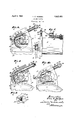
- Figure 1 is a view of the starter mechanism, partly in side elevation and partly in section and partly broken away.
- Fig. 2 is an end elevation of the starter mechanism and a segment of the engine gear shown in dotted lines associated therewith.
- Fig. 3 is substantially the same as Fig. 2 with a part of the housing in section and with the starter pinion in mesh wih the engine gear instead of being in neutral position.
- Fig. 4 shows the same as Fig. 2 with the parts in an intermediate position after the starter pinion and its support have been kicked out and first caught before the pedal rod has returned to normal.
- Fig. 5 is a detail of the mounting of the catch.
- the starter mechanism includes an electric motor 11 having an end housing plate 12, as shown in Figs. 1 and 2, and an electric motor shaft 13 with a motor pinion 14 secured thereon, these parts being substantially concentric with the motor housing.
- the motor is mounted with its front end beside the engine gear, substantially as shown in Fig. 1, with the motor pinion 14, the starter pinion 15, and the engine gear 10 being mounted substantially in the same plane.
- Starter pinion 15 is here mounted so as to be always in mesh with the motor pinion.
- the starter is on a spindle or pin 16 secured in the free end of a block 17 that is at its other end pivoted on the motor shaft 13.
- the starter pinion 15 has a swinging movement concentrically of motor shaft 13 and motor pinion 14, and thus can be swung into neutral and normal postion, as seen in Fig. 2, or into meshing and engine starting position, as shown in Fig. 3.
- the starter pinion is held out of mesh in neutral position, as shown in Fig. 2, by a pawl-like catch 18 which is pivoted at one end on a pin 19 which extends through a pair of ears or lugs 20 from block 17, as seen in Fig. 5, and is spring pressed upward by plug 117 and spring 118 in ahole in block 17, as seen in Fig. 5'.
- the pawl-like catch 18 is adapted to catch on one of the circular shoulders 21 and 22 on a pedal push rod 23 that extends chord-like through the housing member 12 of the motor, as shown in Fig. 2. It is forcibly and positively moved downward, usually by the foot, in order to release the starter mechanism and close the circuit to start the motor as indicated in Fig. 3.
- Said pedal rod is held in its outer and neutral position by a relatively strong spring 24 surrounding the rod and extending between the housing 12 and nuts 25 and 26. Said rod is limited in its outward movement to normal position by a stop nut 27 on its lower end, although it may be stopped by the arm 28 on the upper end of the pedal rod. The end of this arm extends under the rigid metal strap 29 that is secured upon the motor 11, as seen in Fig. 1.
- the means for holding the starter pinion in neutral position should be relatively positive so as never to release the same unless positively and intentionally efi'ected. If in this construction the catch 18 should accidentally be disengaged from a shoulder 21 or 22 the spring 30 would immediately move the starter pinion into mesh with the engine gear and if it were running the latter would immediately kick the starter gear back and the catch 18 would engage shoulder 21 or 22, depending upon whether the pedal rod were pushed down or not, and no further idle movement could occur.
- Spring 24 on the push rod 23 is many times stronger than the spring 30, and spring 30, while always strong enough to pull the starter pinion down into mesh with the engine gear, is, at the same time, weak enough to permit the starter pinion and the block 17 to be kicked up out of meshing position and be caught and held by the catch 18 and shoulder 21 or 22.
- the electric motor is equipped with terminals 31 and 32 and the contact plate or tongue 33 is in position to be engaged by the relatively rigid arms or bar 28 when the pedal rod is depressed.
- the arrangement is such, preferably, that the pedal rod will first release the catch 18 and enable the spring 30 to move the starter pinion down into mesh with the engine gear as shown in Fig. 3, before the electric circuit is closed in motor 11, so that the starter pinion will bein mesh with the engine gear before its motor begins rotation.
- this starter is relatively fool-proof and no part thereof will go wild or have accidental movement that would be injurious to the mechanism, as has been so common a trouble in starters heretofore. If the catch 18 might once in awhile during the return movement of the starting pinion, fail to catch on a shoulder 21 or 22 the first time, it will be immediately kicked back and will catch the second time, and will not be left idle for constant repetition of such kicking movement.
- a starter for internal combustion engines including a motor shaft, a pinion secured thereon, a starter pinion, a block pivoted at one end and on which the starter pinion is mounted at the other end and the movement of said block will be concentric with the aXis of the motor pinion, a spring connected with said block which always tends to move the same to bring the motor pinion into mesh with the engine gear and weak enough to permit the block and starter pinion to be kicked out of the way by the engine gear when the engine is started, a catch pivoted to the free end of said block, and means for engaging and holding said catch and other parts in neutral position, which means must be positvely operated to release said catch.
- a starter for internal combustion engines including a motor shaft, a pinion secured thereon, a starter pinion, a block pivoted at one end and on which the starter pin ion is mounted at the other end and the movement of saidblock will be concentric with the axis of the motor pinion, a spring connected with said block which always tends to move the same to bring the motor pinion into mesh with the engine gear and weak enough to permit the block and starter pinion to be kicked out of the way by the engine gear when the engine is started, a spring pressed catch pivoted to the free end of said block, means for engaging and holding said catch,
- a starter for interal combustion engines including a motor pinion, a motor shaft on which said pinion is secured, a block pivoted concentric to said shaft, a starter pinion mounted on the free end of said block, a spring connected with said block which always tends to move said block to bring the starter pinion into mesh with the engine gear, a catch pivoted to the free end of said block, a pedal rod located near said catch and adapted to be longitudinally moved positively, and av circular shoulder on said rod adapted to be engaged by said catch when the starter pinion is kicked out of mesh by the engine gear and to hold the same in neutral position.
- a starter for internal combustion engines including a motor pinion, a motor shaft on which said pinion is secured, a block pivoted concentric to said shaft, a starter pinion mounted on the free end of said block, a spring connected with said block which always tends to move said block to bring the starter pinion into mesh with the engine gear, a catch pivoted to the free end of said block, a pedal rod located near said catch and adapted to be longitudinally moved positively and a circular shoulder on said rod adapted to be engaged by said catch when the starter pinion is kicked out of mesh by the engine gear and to hold the same in neutral position, a stop at one end of said rod for limiting its upward movement, and a relatively strong spring on the other end of .said rod tending to force it outward whereby positive force is required to move said rod and release said catch.
- a starter for internal combustion engines including a motor pinion, a starter pinion, a block pivoted at one end concentric to the axis of the motor pinion mounted on the other end of said block, means for moving the block and starter pinion to bring the latter into mesh with the engine gear, a catch pivoted to the free end of said block, a spring imbedded in said block and tending to push said catch away from the block, and means for engaging and holding said catch and other parts in neutral position.
- a starter for internal combustion engines including a motor pinion, a starter pinion, a block pivoted at one end concentric to the axis of the motor pinion mounted on the other end of said block, means for moving the block and starter pinion to bring the latter into mesh with the engine gear, a catch pivoted to the free end of said block, a spring imbedded in said block and tending to push said catch away from the block, a pedal rod located near said catch and adapted to be longitudinally moved positively, a pair of successive circular shoulders on said rod adapted to be engaged with said catch when the starter pinion is kicked out of mesh by the engine gear and to hold the same in neutral position, and a pin on the motor in position to be engaged by the beveled head of said catch when the pedal rod returns to normal and disengage said catch from the uppermost circular shoulder so that it will engage the following circular shoulder, substantially as set forth.
Landscapes
- Engineering & Computer Science (AREA)
- Chemical & Material Sciences (AREA)
- Combustion & Propulsion (AREA)
- Mechanical Engineering (AREA)
- General Engineering & Computer Science (AREA)
- Connection Of Motors, Electrical Generators, Mechanical Devices, And The Like (AREA)
Description
April 5, 1932. v. c. HODGES 1,852,653
ENGINE STARTER Filed Jan; 16,1931
Izzvezziar.
He's
Jliiorzze ya.
Patented Apr. 5, 1932 VERA HODGES, F LOS ANGELES, CALIFORNIA ENGINE srnnrnn Application filed January 16, 1931. Serial No. 509,157.
This is a starter, preferably an electric starter, for starting internal combustion engines. It includes a starter pinion adapted to be moved into mesh with the engine gear,
and one feature of the invention is the provision of a spring which always tends to efiect this movement. Another novel feature is the means for substantially and positively catching the starter pinion mounting when it is to kicked out by the engine and'holding it in neutral position until the holding means is positively released.
The invention avoids the dilficulty of the starter pinion accidentally returning to mesh 15 with the engine gear after the engine has been started, and such meshing of the pinion and immediately being kicked out being repeated, and thus wearing and injuring the mechanism and annoying the operator.
The full nature of the invention will be understood from the accompanying drawings and the following description and claims.
In the drawings, Figure 1 is a view of the starter mechanism, partly in side elevation and partly in section and partly broken away. Fig. 2 is an end elevation of the starter mechanism and a segment of the engine gear shown in dotted lines associated therewith. Fig. 3 is substantially the same as Fig. 2 with a part of the housing in section and with the starter pinion in mesh wih the engine gear instead of being in neutral position. Fig. 4 shows the same as Fig. 2 with the parts in an intermediate position after the starter pinion and its support have been kicked out and first caught before the pedal rod has returned to normal. Fig. 5 is a detail of the mounting of the catch.
There is shown in the drawings herein a segment of the engine gear that is associated wlth the shaft of the internal combustion engine and with which the starter mechanism cooperates. The starter mechanism includes an electric motor 11 having an end housing plate 12, as shown in Figs. 1 and 2, and an electric motor shaft 13 with a motor pinion 14 secured thereon, these parts being substantially concentric with the motor housing. The motor is mounted with its front end beside the engine gear, substantially as shown in Fig. 1, with the motor pinion 14, the starter pinion 15, and the engine gear 10 being mounted substantially in the same plane. Starter pinion 15 is here mounted so as to be always in mesh with the motor pinion. The starter is on a spindle or pin 16 secured in the free end of a block 17 that is at its other end pivoted on the motor shaft 13. Therefore, the starter pinion 15 has a swinging movement concentrically of motor shaft 13 and motor pinion 14, and thus can be swung into neutral and normal postion, as seen in Fig. 2, or into meshing and engine starting position, as shown in Fig. 3.
The starter pinion is held out of mesh in neutral position, as shown in Fig. 2, by a pawl-like catch 18 which is pivoted at one end on a pin 19 which extends through a pair of ears or lugs 20 from block 17, as seen in Fig. 5, and is spring pressed upward by plug 117 and spring 118 in ahole in block 17, as seen in Fig. 5'. The pawl-like catch 18 is adapted to catch on one of the circular shoulders 21 and 22 on a pedal push rod 23 that extends chord-like through the housing member 12 of the motor, as shown in Fig. 2. It is forcibly and positively moved downward, usually by the foot, in order to release the starter mechanism and close the circuit to start the motor as indicated in Fig. 3. Said pedal rod is held in its outer and neutral position by a relatively strong spring 24 surrounding the rod and extending between the housing 12 and nuts 25 and 26. Said rod is limited in its outward movement to normal position by a stop nut 27 on its lower end, although it may be stopped by the arm 28 on the upper end of the pedal rod. The end of this arm extends under the rigid metal strap 29 that is secured upon the motor 11, as seen in Fig. 1.
When the pedal rod is depressed by the foot, the pawl-like catch 18 is released from the shoulder 21 on the pedal rod or recedes with said rod as shown in Fig. 3. Such ac tion permits the spring 30 to draw the starter pinion 15 instantly into mesh with the engine gear, as shown in Fig. 3. Spring 30 is secured at one end to the free end of the pinion block 17 and at the other end to a part of the motor housing and always is in mesh and in condition for effecting such movement whenever block 17 is released.
This is a very important feature of the invention inasmuch as it avoids any of the starting mechanism having accidental or undesired movement. The means for holding the starter pinion in neutral position should be relatively positive so as never to release the same unless positively and intentionally efi'ected. If in this construction the catch 18 should accidentally be disengaged from a shoulder 21 or 22 the spring 30 would immediately move the starter pinion into mesh with the engine gear and if it were running the latter would immediately kick the starter gear back and the catch 18 would engage shoulder 21 or 22, depending upon whether the pedal rod were pushed down or not, and no further idle movement could occur.
Spring 24 on the push rod 23 is many times stronger than the spring 30, and spring 30, while always strong enough to pull the starter pinion down into mesh with the engine gear, is, at the same time, weak enough to permit the starter pinion and the block 17 to be kicked up out of meshing position and be caught and held by the catch 18 and shoulder 21 or 22. I
As shown in Fig. 1, the electric motor is equipped with terminals 31 and 32 and the contact plate or tongue 33 is in position to be engaged by the relatively rigid arms or bar 28 when the pedal rod is depressed. The arrangement is such, preferably, that the pedal rod will first release the catch 18 and enable the spring 30 to move the starter pinion down into mesh with the engine gear as shown in Fig. 3, before the electric circuit is closed in motor 11, so that the starter pinion will bein mesh with the engine gear before its motor begins rotation.
Considerable force is required to push the pedal rod from the positon shown in Fig. 2 to that shown in Figs. 3 and 4e, and usually it is held down until the engine is started and, when in such downward position, the catch 18 still engages the shoulder 21, although that is. not necessary. As soon as the engine gear kicks the starter pinion and block 17 back, if the pedal rod is still down, as shown in Figs. 3 and 4, the momentum of the block 17 will push the catch 18 up further so that it will engage the upper shoulder 22, as in Fig.
4. Then when the foot is removed from the pedal rod, the spring 2 1 will return it from its actuated to its normal position shown in Fig. 2, and in such movement a pin 35 in the end of the motor housing, seen in Figs. 2 and 4, will be engaged by the beveled face of the catch 18 so the catch will be pushed off the shoulder 22, whereupon it catches on shoulder said catch 18 will engage the lower shoulder 21, as shown in Fig. 2.
From the foregoing description it will be clear that this starter is relatively fool-proof and no part thereof will go wild or have accidental movement that would be injurious to the mechanism, as has been so common a trouble in starters heretofore. If the catch 18 might once in awhile during the return movement of the starting pinion, fail to catch on a shoulder 21 or 22 the first time, it will be immediately kicked back and will catch the second time, and will not be left idle for constant repetition of such kicking movement.
I claim as my invention:
1. A starter for internal combustion engines, including a motor shaft, a pinion secured thereon, a starter pinion, a block pivoted at one end and on which the starter pinion is mounted at the other end and the movement of said block will be concentric with the aXis of the motor pinion, a spring connected with said block which always tends to move the same to bring the motor pinion into mesh with the engine gear and weak enough to permit the block and starter pinion to be kicked out of the way by the engine gear when the engine is started, a catch pivoted to the free end of said block, and means for engaging and holding said catch and other parts in neutral position, which means must be positvely operated to release said catch. I
2. A starter for internal combustion engines, including a motor shaft, a pinion secured thereon, a starter pinion, a block pivoted at one end and on which the starter pin ion is mounted at the other end and the movement of saidblock will be concentric with the axis of the motor pinion, a spring connected with said block which always tends to move the same to bring the motor pinion into mesh with the engine gear and weak enough to permit the block and starter pinion to be kicked out of the way by the engine gear when the engine is started, a spring pressed catch pivoted to the free end of said block, means for engaging and holding said catch,
and a spring stronger than the first mentioned spring for holding said holding means against movement except when the same is forcibly operated.
3. A starter for interal combustion engines, including a motor pinion, a motor shaft on which said pinion is secured, a block pivoted concentric to said shaft, a starter pinion mounted on the free end of said block, a spring connected with said block which always tends to move said block to bring the starter pinion into mesh with the engine gear, a catch pivoted to the free end of said block, a pedal rod located near said catch and adapted to be longitudinally moved positively, and av circular shoulder on said rod adapted to be engaged by said catch when the starter pinion is kicked out of mesh by the engine gear and to hold the same in neutral position.
4. A starter for internal combustion engines, including a motor pinion, a motor shaft on which said pinion is secured, a block pivoted concentric to said shaft, a starter pinion mounted on the free end of said block, a spring connected with said block which always tends to move said block to bring the starter pinion into mesh with the engine gear, a catch pivoted to the free end of said block, a pedal rod located near said catch and adapted to be longitudinally moved positively and a circular shoulder on said rod adapted to be engaged by said catch when the starter pinion is kicked out of mesh by the engine gear and to hold the same in neutral position, a stop at one end of said rod for limiting its upward movement, and a relatively strong spring on the other end of .said rod tending to force it outward whereby positive force is required to move said rod and release said catch.
5. A starter for internal combustion engines, including a motor pinion, a starter pinion, a block pivoted at one end concentric to the axis of the motor pinion mounted on the other end of said block, means for moving the block and starter pinion to bring the latter into mesh with the engine gear, a catch pivoted to the free end of said block, a spring imbedded in said block and tending to push said catch away from the block, and means for engaging and holding said catch and other parts in neutral position.
6. A starter for internal combustion engines, including a motor pinion, a starter pinion, a block pivoted at one end concentric to the axis of the motor pinion mounted on the other end of said block, means for moving the block and starter pinion to bring the latter into mesh with the engine gear, a catch pivoted to the free end of said block, a spring imbedded in said block and tending to push said catch away from the block, a pedal rod located near said catch and adapted to be longitudinally moved positively, a pair of successive circular shoulders on said rod adapted to be engaged with said catch when the starter pinion is kicked out of mesh by the engine gear and to hold the same in neutral position, and a pin on the motor in position to be engaged by the beveled head of said catch when the pedal rod returns to normal and disengage said catch from the uppermost circular shoulder so that it will engage the following circular shoulder, substantially as set forth.
In witness whereof, I have hereunto afiixed my signature.
VERA G. HODGES.
Priority Applications (1)
| Application Number | Priority Date | Filing Date | Title |
|---|---|---|---|
| US509157A US1852653A (en) | 1931-01-16 | 1931-01-16 | Engine starter |
Applications Claiming Priority (1)
| Application Number | Priority Date | Filing Date | Title |
|---|---|---|---|
| US509157A US1852653A (en) | 1931-01-16 | 1931-01-16 | Engine starter |
Publications (1)
| Publication Number | Publication Date |
|---|---|
| US1852653A true US1852653A (en) | 1932-04-05 |
Family
ID=24025521
Family Applications (1)
| Application Number | Title | Priority Date | Filing Date |
|---|---|---|---|
| US509157A Expired - Lifetime US1852653A (en) | 1931-01-16 | 1931-01-16 | Engine starter |
Country Status (1)
| Country | Link |
|---|---|
| US (1) | US1852653A (en) |
-
1931
- 1931-01-16 US US509157A patent/US1852653A/en not_active Expired - Lifetime
Similar Documents
| Publication | Publication Date | Title |
|---|---|---|
| US1852653A (en) | Engine starter | |
| US2706025A (en) | Diesel shutdown mechanism | |
| US2747414A (en) | Starter | |
| US4919091A (en) | Ignition switch arrangement for an internal combustion engine having an electrical ignition system | |
| FR507602A (en) | Device for wedging a lever on an axis | |
| US1792583A (en) | Engine-starting system | |
| US2253125A (en) | Fisching hook, particularly for the catching of big fish | |
| US2302325A (en) | Engine starter gearing | |
| US2070994A (en) | Backfiring release for automatic starting mechanism | |
| SU104935A1 (en) | Device for coupling and disengaging an automobile starter shaft to the flywheel of an internal combustion engine | |
| US2429388A (en) | Engine starter | |
| US1651127A (en) | Starter for engines | |
| US1693342A (en) | Engine starter | |
| US2302245A (en) | Carburetor unloader | |
| US1343501A (en) | Compression-release | |
| US2013294A (en) | Automatic ignition cut-off which op- | |
| US2344463A (en) | Engine starter gearing | |
| US1563839A (en) | Starting device for internal-combustion engines | |
| US2286989A (en) | Engine starter control | |
| US2152287A (en) | Automatic safety device for internal combustion engines | |
| US1449865A (en) | Engine starter | |
| SU64864A1 (en) | Back Shock Protection Device when starting internal combustion engines | |
| GB261032A (en) | Improvements in starters for engines | |
| US1343531A (en) | Automobile-cranker | |
| US2897806A (en) | Vacuum responsive throttle control for internal combustion engines |