US1852639A - Grinding wheel dresser tool - Google Patents
Grinding wheel dresser tool Download PDFInfo
- Publication number
- US1852639A US1852639A US348694A US34869429A US1852639A US 1852639 A US1852639 A US 1852639A US 348694 A US348694 A US 348694A US 34869429 A US34869429 A US 34869429A US 1852639 A US1852639 A US 1852639A
- Authority
- US
- United States
- Prior art keywords
- spindle
- discs
- dresser
- tool
- sleeve
- Prior art date
- Legal status (The legal status is an assumption and is not a legal conclusion. Google has not performed a legal analysis and makes no representation as to the accuracy of the status listed.)
- Expired - Lifetime
Links
Images
Classifications
-
- B—PERFORMING OPERATIONS; TRANSPORTING
- B24—GRINDING; POLISHING
- B24B—MACHINES, DEVICES, OR PROCESSES FOR GRINDING OR POLISHING; DRESSING OR CONDITIONING OF ABRADING SURFACES; FEEDING OF GRINDING, POLISHING, OR LAPPING AGENTS
- B24B53/00—Devices or means for dressing or conditioning abrasive surfaces
- B24B53/12—Dressing tools; Holders therefor
- B24B53/14—Dressing tools equipped with rotary rollers or cutters; Holders therefor
Definitions
- This invention is concerned with tools for accurately dressing grinding wheels used on production grinding machines, and is particularly concerned with that type of tool wherein a plurality of spur or toothed discs are utilized as the Wheel trimming or dressing medium.
- the general object of the present invention therefore is to provide a combination of elements in a grinding wheel dresser of the spur disc type which will not deteriorate in use and Serial No. 348,694.
- spur discs may be conveniently and accurately replaced by new sets of spur discs, and the free spinning action of the rotating elements of the tool assured.
- a further object of the present invention is the provision of a unitary construction for the spur discs and a retainer medium therefor which will permit a plurality of discs to be properly assembled upon and rigidly secured to a retaining means in such manner that the teeth or spurs of the respective discs may be angularly displaced relative to each other whereby any desired degree of cutting or trimming action may be obtained by merely varying the assembly relation of the discs.
- a further object of our invention is the provision of a dresser element and a bearing arrangement therefor which will permit quick replacement of a depreciated element by a new element while maintaining a. dust and grit proof bearing assembly.
- a further object of our invention is the provision of a compact sturdy body for the tool that will permit of a quick removal and accurate replacement of the bearing mechanism and dresser spindle.
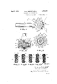
- Fig. 1 is a side View of a grinding wheel dresser embodying the features of our invention
- Fig. 2 is a cross sectional view taken through the tool along the line 2--2 of Fig. 1
- Fig. 3 is an enlarged cross sectional view taken transversely of the dresser unit and spindle
- Fig. l is a telescopic view showing the manner of rapid assembly of the dresser unit upon the spindle
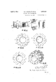
- Fig. 5 is a View similar to Fig. 3 showing the manner of assembling spur discs upon a disc retaining means
- Fig. 6 is a perspective view of an assembled dresser element
- Figs. 7 to 11 inclusive are a few illustrations of the combinations possible in the assembly of the spur discs at the source or manufacture of the tool
- Figs. 12 and 13 are modified forms of securing arrangements between the spur discs and the retaining means upon which they are mounted.
- Our invention contemplates the provision of a grinding wheel dresser tool which is developed in such way that it may be designed within certain dimensional limitations determined by the clearances or spaces, provided in production grinding machines, for the use of diamond tools. While meeting this primary condition whereby the present tool is utilizable as a substitute for the diamond tool we have arranged a bearing construction and a spindle which supports the dresser element so that the spindle and bearings may be readily removed from the body of the tool without necessitating disorganization of the cooperative relationship between the bearings and spindle mechanisms.
- Such an arrangement permits us to seal the bearings in an efiective manner to prevent ingress of the abrasive waste from the grinding wheel when the wheel is being dressed or trimmed, and we have also arranged the bearing and spindle mechanism whereby the bearings are of such proportion as to efiiciently support the spindle when the latter is subjected to high speeds and stresses while also permitting the dresser unit topass over the assembled bearings.
- this dresser unit which comprises a plurality of spur or toothed discs, may be permanently mounted upon a sleeve or barrel at the source of manufacture of the tool thus eliminating annoyance and loss of time to the operator of the grinding machine occasioned by the assembly of loose discs upon a w spindle or sleeve or barrel as has been the disc bore and the barrel or sleeve upon which the discs are to be mounted is such that a plurality of discs may be mounted upon the sleeve with any desired angular displacement between the spurs or teeth of adjacent discs in the unit.
- a series of dresser units may be carried in stock, the eifective cutting ordressing action of which will depend upon the angular relation of the spurs or teeth of the discs comprising the units whereby dresser units become available for grinding wheels of different diameters and of varying grain structure.
- All of the rotating parts of the tool are designed in such manner that the rotating mechanism is completely balanced and precision bearings are used whereby the desired spinning action is assured.
- a dresser tool which fulfills the various purposes set forth, and such a tool may comprise a body provided with a replaceable shank 16 of such diameter that the shank will fit a bore in the carrier provided on the grinding machine, the center of such bore being in the horizontal plane of the center of the axis of the grinding wheel.
- the body 15 as shown in Figs. 1 and 2 is formed to provide two arms 18 and 19, suitably formed to engage and accurately support non-rotating bearing sleeves 20 and 21. These arms are integrally connected by a central stiffening portion 15a of the body and impart rigidity and strength thereto.
- the upper part of the body comprises a removable cap formed somewhat complementary to the body member 15 to engage the upper half of sleeves 20 and 21 to firmly clamp the bearing sleeves 20 and two accessible bolts 26 are provided intermediate the rear end 25a of the cap and the bearing sleeve engaging arms or portions thereof, whereby the sleeves 20 and 21 may be accurately and firmly held in position.
- the bearing sleeves 20 and 21 support and house outer stationary bearing members 28 and inner rotative bearing members 30 are fixed to the ends of a spindle 31 by any suitable means such as pairs of lock nuts shown at 33.
- the spindle is provided with a bushing 35 which is fixed to the spindle in any Slllbi le manner such as by the use of look a; and the bushing is of such shape that the bearing mechanism shown to the left in Fig.
- the spindle bushi 36 is shaped to receive a dresser unit generally indicatel at 41 (see Figs. 2 and 1-) and is provided ux h a suitable shoulder at the left end against which the dresser unit 41 may be clamped by a lock nut 43 in threaded engagement with the right end of the bearing bushing.
- a second cooperating nut 44 is provided of special form whereby the bearing; mechanism shown to the left in Fig. 2 may be sealed against 5 i abrasive m tter in the obvious in A trated.
- the non-rotating bearing sleeves 2!) and 21 are provided with end closure plu 46, thus comple ing the enclosure of the re spective bearing mechanisms.
- the bearing slee vc 21 is or less diameter than that portion of the spindle bushing w..ich shifts and supports the dresser element unit 41 whereby when the nuts 13 and id are removed the dresser element 41 may be readily replaced without disrganizing the cooperative relationship be tween the spindle 31 the spindle bushing 35 and the respective bearing mechanisms as clearly shown in Fig. 4. All of the foregoing described parts are made with precision whereby rotating balance is maintained.
- Figs. 3 and 5 we illustrate the particular form of retaining means and upon which the spur discs are assembled.
- the spur discs 50 as will be apparent are of such diameter that the spurs will be ofconsiderable length and the width of the spurs is dependent of course upon the number of spurs formed on each disc. In the present instance it has been found desirable to provide 12 "teeth or spurs on each disc and all of the discs are of the same shape and size.
- a plurality of the discs are assembled upon a retaining means comprising a sleeve 52 having an internal diameter accurately machined to closely but slid-ably fit the spindle bushing 35, and the outer circumference of the sleeve is fluted in the manner shown in Fig. 8, whereby the angle A, defined by the arc of each circumferential spur face, will include a. plurality of the flutes formed on the sleeve 52.
- the central bore of the discs may be correspondingly fluted, whereby the discs may be assembled at the source of manufacture upon the sleeve 52 with the teeth of each adjacent disc angularly displaced an amount corresponding to the angle defined by one or more flutes formed on the sleeve 52 as desired.
- Figs. 7 illustrates the circumferential relationship or angular displacement of the spur edges B, which edges constitute the actual pitting or cutting portions of the spurs when used on a grinding wheel.
- Fig. 8 the relationship of the spurs is shown when each disc is angularly displaced on the sleeve an amount corresponding to two flutes.
- Figs. 9, 10 and 11 further illustrate the results ob tained in the disc assembly by a progression of the angular displacements of the discs relative to each other.
- This particular assembly arrangement also has the following advantages: A large number of dresser unit combinations having varying cutting actions are obtainable from only one set of punches and dies for all of the discs 50 are uniform in shape and size.
- the discs are hardened during the course of the manufacture thereof and frequently warp and when assembling them in the manner illustrated, each disc has the central bore thereof in an intimate and locking engagement with the sleeve 52; hence it becomes practical to assemble the discs at the source of manufacture upon the sleeve, press them together and upset the ends of the sleeve 52 against suitable washer members 54.
- a dresser unit thus made and assembled, will remain in perfect balance when in use and during the time the spurs are gradually ground down.
- Fig. 12 we show a modified form of assembly where the flutes are formed only on the central bore of the discs and two small key members 55 are provided in diametrically opposite positions to maintain the balance.
- Fig. 13 the reversal of the arrangement of Fig. 12 is illustrated, where the flutes are formed on the sleeve 52 in the manner described, but only two diametrically opposite internal teeth 58 are formed on the discs 50.
- the design of the body is such that the tool may be utiiized in the spaces provided for the use of a diamond tool.
- the shank 16 may be removed from the body to attach a shank of a different diameter, depending upon the bore provided in the grinding machine for the reception of the shanks of diamond tools.
- the body is-designed in such manner that only two bolts are required to hold the entire mechanism together and which are readily accessible.
- the design of the top part of the body is such that the bolts are quite effective in causing the removable spindle and bearing mechanism to be firmly and accurately held in place relative to the center of the shank and the axis of the grinding wheel to be treated.
- All rotating parts are of such form that they can be machined with precision whereby when the dresser element is subjected to high rotative speed from 8000 to 12000 It. P. M. the mechanism is in practically perfect rotational balance, thus causing a spinning action and consequent eiiiciency of the cutting spurs.
- the nature of the bearings and supporting mediums therefore is such as to exclude abrasive dust and grit, thus greatly prolonging the life of the bearings and the assembly can be made at the source of manufacture of the tool and remain cooperatingly undisturbed when placed in industrial use, thus eliminating the human factor in the care of the tool and the bearing design and spindle is such that the dresser unit may be readily replacer when worn down.
- the dresser unit is of such design as to be extremely flexible in the desired range of cutting actions thereof and finally all of the foregoing is accompanied in an accurate, but economical manner and the use of the tool in the industries is therefore of great advantage to both the manufacturer and the workmen.
- a spool of dresser elements relatively fixed and a spindle upon which the spool is fixed and bearing mechanisms rotatively supporting the spindle and cooperatively fixed thereto, said spool comprising a plurality of toothed discs having the central openings thereof formed to engage the entire outer circumferential surface of a disc supporting and retaining sleeve said sleeve having an inner bore formed to be greater than the greatest outer dimen sion of said bearing mechanisms whereby the sleeve and discs can be removed as a unit from the spindle without disorganization of the cooperative relation of the spindle and bearing mechanisms.
- a spindle upon which the spool is fixed and bearing mechanisms rotatively supporting the spindle and cooperatively fixed thereto and including housing members
- said spool comprising a plurality of toothed discs having the central opening thereof formed to engage the outer surface of a disc supporting and retaining sleeve, the discs being permanently secured to the sleeve with the teeth of adjacent discs out of alignment and said sleeve having an inner bore formed to be greater than the greatest outer dimension of the housing member of one of said bearing mechanisms whereby the sleeve and discs can be removed as a unit from the spindle without disorganization of the cooperative relation of the spindle and bearing mechanisms.
- a spool of dresser elements relatively fixed, a spindle and bearing mechanism rotatively supporting the spindle, said spool comprising a plurality of toothed discs and a uniformly fluted sleeve having the angular pitch of the flutes considerably less than the an le defined by the arc of the circumferential face of each tooth of the disc, the discs having the bores thereof formed to fit the sleeve flutes and the discs being mounted upon the sleeve with the teeth of each disc angularly displaced relative to theteeth of an adjacent disc, said angularity of displacement being equal to or a multiple of said flute pitch angle.
- a dresser tool of the character described the combination of a rotatable spindle, a spindle bushing mounted thereon, means for securing the bushing to the spindle whereby the spindle and bushing will rotate in unison, a bearing mechanism attached to each end of the spindle, each bearing mechanism having an element secured to the spindle and cooperating bearing elements, a body for removably supporting said bearing mechanisms and spindle, said bearing mechanisms having enclosing means for preventing the ingress of abrasive grit, said enclosing means and said bushing being formed to comprise part of the enclosure for said bearings, a dresser unit having a slip fit on said bushing, said dresser unit having an internal bore of sufiicient size to pass over one of said enclosing means and means for securing the dresser unit to the bushing whereby the spindle bushing and dresser unit revolve in unison, said means comprising part of the mechanical enclosure for one of said bearings.
- a dresser tool of the character described the combination of a rotatable spindle, a spindle bushing mounted thereon, means for securing the bushing to the spindle whereby he spindle and bushing will rotate in unison, a bearing mechanism attached to each end of the spindle and a body for supporting said bearing mechanisms, said bearing mechanisms being provided with housing members to prevent the ingress of abrasive grit, said bushing being formed to comprise part of the enclosure for one of said bearings, and a dresser unit mounted upon the bushing, said dresser unit having an internal bore of sutlicient size to pass over one of said housing members.
- a dressing unit mounted in the frame and removable therefrom as a unit, said dressing unit comprising a rotatable spindle, anti-friction bearings secured to opposite ends of said spindle, said spindle arranged so that its diameter intermediate the bearings is greater than thediameter of the bearings, a sleeve carried by said spindle, a plurality of dressing elements secured in place on said sleeve, means to secure the sleeve on said spindle intermediate said bearings, and wherein said sleeve and dressing elements are removable as a unit from the spindle without disturbing the relation between or the removal of either of said bearings from the spindle.
Landscapes
- Engineering & Computer Science (AREA)
- Mechanical Engineering (AREA)
- Grinding-Machine Dressing And Accessory Apparatuses (AREA)
Description
April 1932- w. D. BARTLETT ET AL 1,852,639
GRINDING WHEEL DRE SSER TOOL Filed March 21. 1929 2 Sheets-Sheet l Pimento WAMMQD i xp 1 April .5 1932, w. D BARTLETT ET AL 1,852,639
GRINDING WHEEL DRESSER TOOL Filed March 21, 1929 2 Sheets-Sheet 2 Patented Apr. 5, 1932 UNETED STATES ATENT OFFICE WILLIAM D. BARTLETT, OF CLEVELAND, .ANI) DANIEL KELLEHER, OF BEBEA, OHIO, AS- SIGNORS TO THE ROSS MANUFACTURING COIVIPANY, OF CLEVELAND, OHIO, A COR- POBATION OF OHIO GRINDING WHEEL DRESSER TOOL Application filed March 21, 1929.
This invention is concerned with tools for accurately dressing grinding wheels used on production grinding machines, and is particularly concerned with that type of tool wherein a plurality of spur or toothed discs are utilized as the Wheel trimming or dressing medium.
Tools of this general type are extensively used in the art in substitution of the diamond cutter or dresser. The diamond cutter or dresser while. being satisfactory to trim or dress a grinding Wheel, nevertheless entails a number of annoyances to the manufacturer and also to the grinding machine operator who is usually working on a piece rate basis in that the diamond point is expensive, b-e comes displaced or lost, the points have to be reset frequently, etc. Likewise the use of substitute dressers of the spur wheel type have had disadvantages in that the discs must have some form of accurate bearing support due to their high speed of rotation and the use of the tool in an abrasive environment causes rapid deterioration of the bearings thus destroying the efliciency and accuracy of the dressing action of the tool and necessitating frequent and costly bearing replacement. Tools of this character must be provided with spur discs, the teeth of the discs being arranged in delinite angular relations whereby the desired cutting action is effected upon the grinding wheel by the radial edges of the teeth, but the design limitations as to outside diameter of the discs, etc. are such that heretofore it has been considered the least of several evils to frequently replace the bear lngs.
As stated the grinding operator is usually employed on a piece work basis and the replacement of Worn out discs and bearings is undertaken hastily by him with the result that the discs are frequently assembled in the dresser tool incorrectly and the hearings incorrectly adjusted whereby the high spinning rate of the dresser unit'of the tool is prevented.
The general object of the present invention therefore is to provide a combination of elements in a grinding wheel dresser of the spur disc type which will not deteriorate in use and Serial No. 348,694.
in which the spur discs may be conveniently and accurately replaced by new sets of spur discs, and the free spinning action of the rotating elements of the tool assured.
A further object of the present invention is the provision of a unitary construction for the spur discs and a retainer medium therefor which will permit a plurality of discs to be properly assembled upon and rigidly secured to a retaining means in such manner that the teeth or spurs of the respective discs may be angularly displaced relative to each other whereby any desired degree of cutting or trimming action may be obtained by merely varying the assembly relation of the discs.
A further object of our invention is the provision of a dresser element and a bearing arrangement therefor which will permit quick replacement of a depreciated element by a new element while maintaining a. dust and grit proof bearing assembly.
A further object of our invention is the provision of a compact sturdy body for the tool that will permit of a quick removal and accurate replacement of the bearing mechanism and dresser spindle. Other objects of our invention will hereinafter become apparent from the following description which refers to the accompanying drawings, the drawings illustrating a preferred embodiment of the invention.
In the drawings, Fig. 1 is a side View of a grinding wheel dresser embodying the features of our invention; Fig. 2 is a cross sectional view taken through the tool along the line 2--2 of Fig. 1; Fig. 3 is an enlarged cross sectional view taken transversely of the dresser unit and spindle; Fig. l is a telescopic view showing the manner of rapid assembly of the dresser unit upon the spindle; Fig. 5 is a View similar to Fig. 3 showing the manner of assembling spur discs upon a disc retaining means; Fig. 6 is a perspective view of an assembled dresser element; Figs. 7 to 11 inclusive, are a few illustrations of the combinations possible in the assembly of the spur discs at the source or manufacture of the tool, and Figs. 12 and 13 are modified forms of securing arrangements between the spur discs and the retaining means upon which they are mounted.
Our invention contemplates the provision of a grinding wheel dresser tool which is developed in such way that it may be designed within certain dimensional limitations determined by the clearances or spaces, provided in production grinding machines, for the use of diamond tools. While meeting this primary condition whereby the present tool is utilizable as a substitute for the diamond tool we have arranged a bearing construction and a spindle which supports the dresser element so that the spindle and bearings may be readily removed from the body of the tool without necessitating disorganization of the cooperative relationship between the bearings and spindle mechanisms. Such an arrangement permits us to seal the bearings in an efiective manner to prevent ingress of the abrasive waste from the grinding wheel when the wheel is being dressed or trimmed, and we have also arranged the bearing and spindle mechanism whereby the bearings are of such proportion as to efiiciently support the spindle when the latter is subjected to high speeds and stresses while also permitting the dresser unit topass over the assembled bearings. e have given particular attention to the development of a dresser unit which can be satisfactorily used with the assembled spindle and bearing mechanisms referred to whereby this dresser unit, which comprises a plurality of spur or toothed discs, may be permanently mounted upon a sleeve or barrel at the source of manufacture of the tool thus eliminating annoyance and loss of time to the operator of the grinding machine occasioned by the assembly of loose discs upon a w spindle or sleeve or barrel as has been the disc bore and the barrel or sleeve upon which the discs are to be mounted is such that a plurality of discs may be mounted upon the sleeve with any desired angular displacement between the spurs or teeth of adjacent discs in the unit. Thus, a series of dresser units may be carried in stock, the eifective cutting ordressing action of which will depend upon the angular relation of the spurs or teeth of the discs comprising the units whereby dresser units become available for grinding wheels of different diameters and of varying grain structure. All of the rotating parts of the tool are designed in such manner that the rotating mechanism is completely balanced and precision bearings are used whereby the desired spinning action is assured. V
In Figs. 1 and 2 of the drawings we illustrate a construction of dresser tool which fulfills the various purposes set forth, and such a tool may comprisea body provided with a replaceable shank 16 of such diameter that the shank will fit a bore in the carrier provided on the grinding machine, the center of such bore being in the horizontal plane of the center of the axis of the grinding wheel. The body 15 as shown in Figs. 1 and 2, is formed to provide two arms 18 and 19, suitably formed to engage and accurately support non-rotating bearing sleeves 20 and 21. These arms are integrally connected by a central stiffening portion 15a of the body and impart rigidity and strength thereto.
The upper part of the body comprises a removable cap formed somewhat complementary to the body member 15 to engage the upper half of sleeves 20 and 21 to firmly clamp the bearing sleeves 20 and two accessible bolts 26 are provided intermediate the rear end 25a of the cap and the bearing sleeve engaging arms or portions thereof, whereby the sleeves 20 and 21 may be accurately and firmly held in position. The bearing sleeves 20 and 21 support and house outer stationary bearing members 28 and inner rotative bearing members 30 are fixed to the ends of a spindle 31 by any suitable means such as pairs of lock nuts shown at 33. The spindle is provided with a bushing 35 which is fixed to the spindle in any Slllbi le manner such as by the use of look a; and the bushing is of such shape that the bearing mechanism shown to the left in Fig. 2 can be enclosed by reason of an extension 2864 which is overlapped by the left end of the spindle lmsliiiig We provide a seal' n'iedium in the form of an annular felt r or cork ring 40 disposed in a suitable groove 'lori ed in the extension 28a of the sleeve 28 and these rings are V-shaped whereby only a minimum contact is made with the bushing 35 to avoid setting up friction.
The spindle bushi 36 is shaped to receive a dresser unit generally indicatel at 41 (see Figs. 2 and 1-) and is provided ux h a suitable shoulder at the left end against which the dresser unit 41 may be clamped by a lock nut 43 in threaded engagement with the right end of the bearing bushing. A second cooperating nut 44 is provided of special form whereby the bearing; mechanism shown to the left in Fig. 2 may be sealed against 5 i abrasive m tter in the obvious in A trated. The non-rotating bearing sleeves 2!) and 21 are provided with end closure plu 46, thus comple ing the enclosure of the re spective bearing mechanisms.
As shown in Figs. 2 and 1 the bearing slee vc 21 is or less diameter than that portion of the spindle bushing w..ich shifts and supports the dresser element unit 41 whereby when the nuts 13 and id are removed the dresser element 41 may be readily replaced without disrganizing the cooperative relationship be tween the spindle 31 the spindle bushing 35 and the respective bearing mechanisms as clearly shown in Fig. 4. All of the foregoing described parts are made with precision whereby rotating balance is maintained.
In Figs. 3 and 5 we illustrate the particular form of retaining means and upon which the spur discs are assembled. The spur discs 50 as will be apparent are of such diameter that the spurs will be ofconsiderable length and the width of the spurs is dependent of course upon the number of spurs formed on each disc. In the present instance it has been found desirable to provide 12 "teeth or spurs on each disc and all of the discs are of the same shape and size.
A plurality of the discs are assembled upon a retaining means comprising a sleeve 52 having an internal diameter accurately machined to closely but slid-ably fit the spindle bushing 35, and the outer circumference of the sleeve is fluted in the manner shown in Fig. 8, whereby the angle A, defined by the arc of each circumferential spur face, will include a. plurality of the flutes formed on the sleeve 52. The central bore of the discs may be correspondingly fluted, whereby the discs may be assembled at the source of manufacture upon the sleeve 52 with the teeth of each adjacent disc angularly displaced an amount corresponding to the angle defined by one or more flutes formed on the sleeve 52 as desired.
One series of obtainable assemblies of the dresser unit is illustrated in Figs. to 11, inclusive. Fig. 7 illustrates the circumferential relationship or angular displacement of the spur edges B, which edges constitute the actual pitting or cutting portions of the spurs when used on a grinding wheel. When the angular displacement as shown in Fig. 7 is only one flute, a dresser unit is obtained which is suitable for the trimming or dressing of grinding wheels of fine grain. In Fig. 8 the relationship of the spurs is shown when each disc is angularly displaced on the sleeve an amount corresponding to two flutes. Figs. 9, 10 and 11 further illustrate the results ob tained in the disc assembly by a progression of the angular displacements of the discs relative to each other.
It will be apparent that the progression of displacement of two flutes per each disc would give intermediate assemblies, etc. and it will be obvious that this particular arrangement of mounting the discs upon the sleeve will permit any desired assembly or the manufacturer of the dressing tool may predetermine a range of 8 or 10 assemblies which could be numbered with the numbers corresponding to industrial uses of the tool for dressing grinding wheels having various diameters and graining characteristics.
This particular assembly arrangement also has the following advantages: A large number of dresser unit combinations having varying cutting actions are obtainable from only one set of punches and dies for all of the discs 50 are uniform in shape and size. The discs are hardened during the course of the manufacture thereof and frequently warp and when assembling them in the manner illustrated, each disc has the central bore thereof in an intimate and locking engagement with the sleeve 52; hence it becomes practical to assemble the discs at the source of manufacture upon the sleeve, press them together and upset the ends of the sleeve 52 against suitable washer members 54. A dresser unit thus made and assembled, will remain in perfect balance when in use and during the time the spurs are gradually ground down. Heretofore the discs have been clamped in an axial direction, and it frequently happened that warped spurs would be contacting with an adjacent disc and as the spurs were down, the warped part was thus removed, permitting all the discs in the assembly to become loose, destroying both balance and cutting efficiency. When the discs were keyed such method resulted in an unbalancing of the rotating parts.
In Fig. 12 we show a modified form of assembly where the flutes are formed only on the central bore of the discs and two small key members 55 are provided in diametrically opposite positions to maintain the balance.
In Fig. 13, the reversal of the arrangement of Fig. 12 is illustrated, where the flutes are formed on the sleeve 52 in the manner described, but only two diametrically opposite internal teeth 58 are formed on the discs 50.
From the foregoing description of our invention, a number of advantages will be found in our present embodiment of a dresser tool heretofore unknown in the art and the design of the body is such that the tool may be utiiized in the spaces provided for the use of a diamond tool. The shank 16 may be removed from the body to attach a shank of a different diameter, depending upon the bore provided in the grinding machine for the reception of the shanks of diamond tools. The body is-designed in such manner that only two bolts are required to hold the entire mechanism together and which are readily accessible. The design of the top part of the body is such that the bolts are quite effective in causing the removable spindle and bearing mechanism to be firmly and accurately held in place relative to the center of the shank and the axis of the grinding wheel to be treated.
All rotating parts are of such form that they can be machined with precision whereby when the dresser element is subjected to high rotative speed from 8000 to 12000 It. P. M. the mechanism is in practically perfect rotational balance, thus causing a spinning action and consequent eiiiciency of the cutting spurs. The nature of the bearings and supporting mediums therefore is such as to exclude abrasive dust and grit, thus greatly prolonging the life of the bearings and the assembly can be made at the source of manufacture of the tool and remain cooperatingly undisturbed when placed in industrial use, thus eliminating the human factor in the care of the tool and the bearing design and spindle is such that the dresser unit may be readily replacer when worn down. The dresser unit is of such design as to be extremely flexible in the desired range of cutting actions thereof and finally all of the foregoing is accompanied in an accurate, but economical manner and the use of the tool in the industries is therefore of great advantage to both the manufacturer and the workmen.
2. In a grinding wheel dresser, aspool of dresser elements relatively fixed, a spindle upon which the spool is fixed and bearing mechanisms rotatively supporting the spindle and cooperatively fixed thereto and including housing members, said spool comprising a plurality of toothed discs having the central opening thereof formed to engage the outer surface of a disc supporting and retaining sleeve, the discs being permanently secured to the sleeve with the teeth of adjacent discs out of alignment and said sleeve having an inner bore formed to be greater than the greatest outer dimension of the housing member of one of said bearing mechanisms whereby the sleeve and discs can be removed as a unit from the spindle without disorganization of the cooperative relation of the spindle and bearing mechanisms.
3. In a grinding Wheel dresser, a spool of dresser elements relatively fixed, a spindle and bearing mechanism rotatively supporting the spindle, said spool comprising a plurality of toothed discs and a uniformly fluted sleeve having the angular pitch of the flutes considerably less than the an le defined by the arc of the circumferential face of each tooth of the disc, the discs having the bores thereof formed to fit the sleeve flutes and the discs being mounted upon the sleeve with the teeth of each disc angularly displaced relative to theteeth of an adjacent disc, said angularity of displacement being equal to or a multiple of said flute pitch angle.
4. In a dresser tool of the character described, the combination of a rotatable spindle, a spindle bushing mounted thereon, means for securing the bushing to the spindle whereby the spindle and bushing will rotate in unison, a bearing mechanism attached to each end of the spindle, each bearing mechanism having an element secured to the spindle and cooperating bearing elements, a body for removably supporting said bearing mechanisms and spindle, said bearing mechanisms having enclosing means for preventing the ingress of abrasive grit, said enclosing means and said bushing being formed to comprise part of the enclosure for said bearings, a dresser unit having a slip fit on said bushing, said dresser unit having an internal bore of sufiicient size to pass over one of said enclosing means and means for securing the dresser unit to the bushing whereby the spindle bushing and dresser unit revolve in unison, said means comprising part of the mechanical enclosure for one of said bearings.
5. In a dresser tool of the character described, the combination of a rotatable spindle, a spindle bushing mounted thereon, means for securing the bushing to the spindle whereby he spindle and bushing will rotate in unison, a bearing mechanism attached to each end of the spindle and a body for supporting said bearing mechanisms, said bearing mechanisms being provided with housing members to prevent the ingress of abrasive grit, said bushing being formed to comprise part of the enclosure for one of said bearings, and a dresser unit mounted upon the bushing, said dresser unit having an internal bore of sutlicient size to pass over one of said housing members.
6. In a grinding tool a frame, a dressing unit mounted in the frame and removable therefrom as a unit, said dressing unit comprising a rotatable spindle, anti-friction bearings secured to opposite ends of said spindle, said spindle arranged so that its diameter intermediate the bearings is greater than thediameter of the bearings, a sleeve carried by said spindle, a plurality of dressing elements secured in place on said sleeve, means to secure the sleeve on said spindle intermediate said bearings, and wherein said sleeve and dressing elements are removable as a unit from the spindle without disturbing the relation between or the removal of either of said bearings from the spindle.
In testimony whereof we hereunto aflix our signatures.
W. D. BARTLETT. DANIEL KELLEHER.
Priority Applications (1)
| Application Number | Priority Date | Filing Date | Title |
|---|---|---|---|
| US348694A US1852639A (en) | 1929-03-21 | 1929-03-21 | Grinding wheel dresser tool |
Applications Claiming Priority (1)
| Application Number | Priority Date | Filing Date | Title |
|---|---|---|---|
| US348694A US1852639A (en) | 1929-03-21 | 1929-03-21 | Grinding wheel dresser tool |
Publications (1)
| Publication Number | Publication Date |
|---|---|
| US1852639A true US1852639A (en) | 1932-04-05 |
Family
ID=23369130
Family Applications (1)
| Application Number | Title | Priority Date | Filing Date |
|---|---|---|---|
| US348694A Expired - Lifetime US1852639A (en) | 1929-03-21 | 1929-03-21 | Grinding wheel dresser tool |
Country Status (1)
| Country | Link |
|---|---|
| US (1) | US1852639A (en) |
Cited By (3)
| Publication number | Priority date | Publication date | Assignee | Title |
|---|---|---|---|---|
| US2742891A (en) * | 1954-01-05 | 1956-04-24 | Kenneth J Wise | Dresser for abrasive wheels |
| RU2179918C2 (en) * | 2000-04-07 | 2002-02-27 | Оренбургский государственный университет | Milling cutter |
| DE10214081B4 (en) * | 2001-03-30 | 2007-12-06 | Fw Roberts Manufacturing Comp. Inc. | Improved ridge for preparing a homogeneous grindstone surface |
-
1929
- 1929-03-21 US US348694A patent/US1852639A/en not_active Expired - Lifetime
Cited By (3)
| Publication number | Priority date | Publication date | Assignee | Title |
|---|---|---|---|---|
| US2742891A (en) * | 1954-01-05 | 1956-04-24 | Kenneth J Wise | Dresser for abrasive wheels |
| RU2179918C2 (en) * | 2000-04-07 | 2002-02-27 | Оренбургский государственный университет | Milling cutter |
| DE10214081B4 (en) * | 2001-03-30 | 2007-12-06 | Fw Roberts Manufacturing Comp. Inc. | Improved ridge for preparing a homogeneous grindstone surface |
Similar Documents
| Publication | Publication Date | Title |
|---|---|---|
| US5054342A (en) | Pipe machining apparatus | |
| US3986543A (en) | Rotary cutter knife | |
| KR930701270A (en) | Apparatus and method for dressing universal rollers and cup-shaped grinding wheels | |
| CA1233024A (en) | Abrasive wheel for pin bore crowns | |
| US1852639A (en) | Grinding wheel dresser tool | |
| US2092714A (en) | Wheel driving mechanism for grinding machines | |
| US1625049A (en) | Grinding machine | |
| US1422200A (en) | Grinding wheel | |
| US891992A (en) | Method of forming conically-shaped ends upon rollers and other objects. | |
| US1058237A (en) | Process and apparatus for grinding the center opening of gear-wheels. | |
| US2805525A (en) | Grinding machine utilizing abrasive discs | |
| GB708183A (en) | Improvements in rotary abrasion and/or polishing tools | |
| US1681087A (en) | Ball-bearing center for machines | |
| US1383601A (en) | Grinding-wheel-truing tool | |
| US1287024A (en) | Grinding-wheel dresser. | |
| JP2516286Y2 (en) | Cup-shaped rotating brush | |
| US1544985A (en) | Mechanism for truing and dressing grinding wheels | |
| DE385701C (en) | Device for grinding the curved side surface of whetstones | |
| US1111064A (en) | Method of truing gears. | |
| US2199053A (en) | Means for dressing grinding wheels | |
| US1601454A (en) | Mounting for burrs | |
| US1558402A (en) | Wheel-truing device | |
| US1756949A (en) | Portable grinding tool | |
| US1988326A (en) | Metal working machine | |
| US2622640A (en) | Multiple clamping disk cutter head |