US1852626A - Propeller for aircraft - Google Patents
Propeller for aircraft Download PDFInfo
- Publication number
- US1852626A US1852626A US455249A US45524930A US1852626A US 1852626 A US1852626 A US 1852626A US 455249 A US455249 A US 455249A US 45524930 A US45524930 A US 45524930A US 1852626 A US1852626 A US 1852626A
- Authority
- US
- United States
- Prior art keywords
- driving shaft
- control member
- propeller
- secured
- blades
- Prior art date
- Legal status (The legal status is an assumption and is not a legal conclusion. Google has not performed a legal analysis and makes no representation as to the accuracy of the status listed.)
- Expired - Lifetime
Links
- 230000033001 locomotion Effects 0.000 description 39
- 238000010276 construction Methods 0.000 description 4
- 230000000694 effects Effects 0.000 description 1
- 239000012530 fluid Substances 0.000 description 1
- 230000007935 neutral effect Effects 0.000 description 1
Images

Classifications
-
- B—PERFORMING OPERATIONS; TRANSPORTING
- B64—AIRCRAFT; AVIATION; COSMONAUTICS
- B64C—AEROPLANES; HELICOPTERS
- B64C11/00—Propellers, e.g. of ducted type; Features common to propellers and rotors for rotorcraft
- B64C11/30—Blade pitch-changing mechanisms
- B64C11/32—Blade pitch-changing mechanisms mechanical
- B64C11/36—Blade pitch-changing mechanisms mechanical non-automatic
Definitions
- propeller is in motion, and without the need of changing the engine speed, and furthermore, if desired, the change of inclination of the propeller blades may be carried beyond their neutral position, to effect a reversing of the tractive force exerted by the propeller on the aircraft.
- My improved construction may be applied in any connection where it is desired to change the inclination of propeller blades
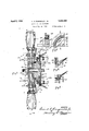
- Figure 1 is a vertical, longitudinal, sectional view through the devices mounting the propeller blades on a driving shaft, and through the mechanism employed to change the inclination of theblades,
- Figure 2 is a vertical, sectional view through a part of the gearing employed to change the inclination of the propeller blades, this view being taken along the lines 2-2 in Figure 3,
- Figure 3 shows in front elevation, onequarter of the gearing and mounting members illustrated in Figure 1, for controlling the changing of the inclination of the blades,
- Figure 5 shows in side elevation the parts illustrated in F igure i
- Figure 6 is a vertical, sectional view through the disk carrying the propeller blades, taken along the line 66 in Figure 1, and in this view, the gearing employed to change the inclination of the propeller blades is shown in front'elevation,
- Figure 7 is a horizontal sectional view through a part of the gearing employed to change the inclination of the propeller blades, this being taken along the line 7-7 in F igure 8, and
- Figure 8 shows in front elevation, onehalf of a combined gear and operating member used to control the inclination of the propeller blades. 7
- a driving shaft 12 is illustrated, upon which the propeller blades 1, 1 are mounted for rotation to drive the aircraft or other device, said shaft being driven from any suitable source of power employed to operate the propeller.
- the shaft 12 carries a flange 11, which is preferably integral with said shaft, and a block 13, which preferably has a fiat sided periphery 13?), is secured to the flange 11 by bolts or screws 23, and is. also keyed to the shaft 12 as indicated.
- the forward portion of the block 13 is of reduced diameter of cylindrical conformation as indicated at 13a, and upon this'portion 13a, a disk 5 is tightly fitted and secured in placeby a suitable key as indicated.
- the shaft 12 on its forward end is provided with anut 18 and washer 19 to hold the parts described in their assembled relation.
- the disk 5 is provided with oppositeradial bores for receivim the stub-shafts 4, 4 to which the propeller blades 1, 1 are rigidly secured, so that the shafts 4c, 4 may turn in said bores.
- the disk 5 is provided with an open ing 5a in which collars 6, 6 are located, said collars being rigidly secured to the shaft 4 longitudinally on said block.
- the member 24 is provided on its outer surface with multiple screw threads of large pitch as indicated in Figures 2 and 7, which mesh with similar threads formed internally in the hub 20, of the bevel gear 2.
- the disk portion of the gear 2 is provided with annular slots 2b as indicated in Figure 6,
- the flange 11 is of greater diameter than the block 13, to retain the member 24 in place on said block between said flange and the disk 5.
- the member 24 has formed on its rear end, a. flange member 24a, extending around the hub 2a and outwardly outside of said hub to constitute one member of a ball bearing 9, the other member of which is a ring 10, engaged by cams 14 carried by stationary brackets 21 supported from any convenient stationary part of the device, for example the engine driving the shaft 12, by bolts or screws 22.
- the cams 14 are rotary and are connected with operating handles 7, so that moving said handles turns the cams 14 to impart longitudinal movement to the ring 10, and thereby similar movementto the member 24.
- the pitch of the blades is preferably arranged so that when the handles 7 are again moved to the position indicated in Figure 4, the fluid pressure on the blades 1, 1 will move the gear 2 in a direction angularly to move the member 24 back to the position indicated in Figure 1.
- a spring 25 may be disposed around the block 13 between the disk 5 and the member. 24.
- Inclination controlling mechanism for propeller blades consisting of the combination of a propeller driving shaft, propeller blades having stub-shafts extending from them towards said driving shaft, bearings for said stub-shafts carried by said driving shaft, a first bevel gear secured to each of said blades, a second bevel gear meshing with said first bevel gears, a control member movable longitudinally of said driving shaft and restrained from rotary movement relatively thereto, spirally disposed cooperating members carried by said control member and said second gear and moving said second gear angularly relatively to said driving shaft for longitudinal movement of said control member, and devices for imparting longitudinal movement to said control memher, said devices comprising rotary cams and means for turning them.
- Inclination controlling mechanism for propeller blades consisting of the combination of a propeller driving shaft, propeller blades having stub-shafts extending from them towards said driving shaft, a disk secured to said driving shaft and having bores receiving said stub-shafts for turning movement therein, a first bevel gear secured to each of said blades, a second bevel gear meshing with said first bevel gears, a block secured to said'driving shaft and having a fiat sided periphery, a control member having a bore fitting said block for longitudinal movement thereon, cooperating spiral gears carried by said second member, and devices or imparting longitudinal movement to said control member.
- Inclination controlling mechanism for propeller blades consisting of the combination of a propeller driving shaft, propeller blades having stub-shafts extending from them towards said driving shaft, a disk secured to said driving shaft and having bores receiving said stub-shafts for turning movement therein, a first bevel gear secured to each of said blades, a second bevel gear meshing with said first bevel gears, a block secured to said driving shaft and having a flat sided periphery, a control member having a bore fitting said block for longitudinal move ment thereon, cooperating spiral gears carried by said second gear and said control member, and devices for imparting longitudinal move cent to said control member, said second gearhaving a hub surrounding the inner portion of said control member, and said control member having a flange portion extending around said hub and outwardly for engagement by said devices.
- Inclination controlling mechanism for propeller blades consisting of the combination of a propeller driving shaft, propeller blades having stub-shafts extending from them towards said driving shaft, 2. disk secured to said driving shaft and having bores receiving said stub-shafts for turning movement therein, a' first bevel gear secured to each of said blades, a second bevel gear meshing with said first bevel gears, a block secured to said driving shaft and having a flat sided periphery, acontrol member having a bore fitting said block for longitudinal movement thereon, cooperating spiral gears carried by saidsecond gear and said control member, and devices for imparting longitudinal movement to-said control member, said second gear having a hub surroundin the innerportion of said control member, an said control member having' a-flangeportion extending around said hub and outwardly for engagement by said devices, said spiral gears being carried by the outer surface of the inner portion of said control member and by the inner portion of said hub.
- Inclination controlling mechanism for propeller blades consisting of the combination of a propeller driving shaft, propeller blades having stub-shafts extending from them towards said driving shaft, a disk se-, cured to said driving shaft and having bores receiving said stub-shafts for turning movement therein, a first bevel gear secured to each of said blades, a second bevel gear-meshing with said first" bevel gears, a block secured to said driving shaft and having a flat.
- a control member having a borefitting said block for longitudinal movement thereon, cooperating spiral gears ear and said control said second carried by said second gear and said control member, devices for imparting longitudinal movement to said control member, and a ing with said first bevel gears, a block secured to said driving shaft and having a fiat sided periphery, a control member having a bore fitting said block for longitudinal movement thereon, cooperating spiral gears carried by gear and said control member, devices for imparting longitudinal movement to said control member, and bolts extending through said disk and said second gear and holding said second gear in mesh with said first gears.
- Inclination controlling mechanism for propeller blades consisting of the combination of a propeller driving shaft, propeller blades having stub-shafts extending from them towards said driving shaft, a disk secured to said driving shaft and having bores receiving said stub-shafts for turning movement therein, a first bevel ear secured to each of-said blades, a second bevel gear meshing with said firstbevel gears, a block secured to said driving shaft and having'a fiat sided periphery, a control member having a bore fittingsaid block for longitudinal movement thereon, cooperating spiral gears carried by said second 'gear and said control member, devices for imparting longitudinal movement to said control member, and a ballbearing between said devices and said control member.
- Inclination controlling mechanism for propeller blades consisting of 'the combination of a propeller driving shaft, propeller blades having stub-shafts extending from them' towards said driving shaft, a disk secured to said driving shaft and having bores receiving said stub-shafts for turning tudinal movement to said control member,
- said devices comprising rotary cams and means for turning them.
- Inclination controlling mechanism for propeller blades consisting of the combination of a propeller driving shaft, propeller blades having stub-shafts extending from them towards said driving shaft, a disk secured to said driving shaft and having bores receiving said stub-shafts for turning movement therein, a first bevel gear secured to each of said blades, a second bevel gear meshing with said first bevel gears, a block secured to said driving shaft and having a flat sided periphery, a control member.
- Inclination controlling mechanism for propeller blades consisting of the combination of a propeller driving shaft, propeller blades having stub-shafts extendin from them towards said driving shaft, a disk secured to said driving shaft and having bores receiving said stub-shafts for turning movement therein, a first bevel gear secured to each of said blades, a second bevel gear meshing with said first bevel gears, a block secured to said driving shaftand having a flat sided periphery, a control member having a bore fitting said block for longitudinal movement thereon, cooperating spiral gears carried by said second gear and said control member, devices for imparting longitudinal movement to said control member, said second gear having a hub surrounding the inner portion of said control member, said control member having a flange portion extending around said hub and outwardly for engagement by said devices, said spiral gears being carried by the outer surface of the inner portion of said control member and by the inner portion of said hub, and a ball-bearing between said devices and said control member, said devices comprising
- Inclination controlling mechanism for propeller blades consisting of the combination of a propeller driving shaft, propeller blades having stub-shafts extending from them towards said driving shaft, a disk secured to said driving shaft and having bores receiving said stub-shafts for turning movement therein, a first bevel gear secured to each of said blades, a second bevel gear meshing With said first bevel gears, a block secured to said driving shaft and having a flat sided periphery, a control member having a bore fitting said block for longitudinal movement thereon, cooperating spiral gears carried by said second gear and said control member, devices for imparting longitudinal movement to said control member, said second gear having a hub surrounding the inner portion of said control member, said control member having a flange portion'extending aroundsaid hub and outwardly for engagement by said devices, said spiral gears being carried by the outer surface of the inner portion of said control member and by the inner portion of said hub, a ball-bearing between said devices and said control member, said devices comprising
Landscapes
- Engineering & Computer Science (AREA)
- Mechanical Engineering (AREA)
- Aviation & Aerospace Engineering (AREA)
- Gear Transmission (AREA)
Description
April 5, 1932. F. A. RINGWALD, JR
PROPELLER FOR AIRCRAFT.
Filed May 24. 1930 2 Sheets-Sheet l INVENTO p i 5, 1932- F. A. RINGWALD, JR 1,852,626
PROPELLER FOR AIRCRAFT Filed May 24, 1930 I ZSheets-Sheet 2 INV.ENTOR I%A Patented Apr. 5, 1932 UNITED STATES PATENT OFFICE FRANK A. RINGW'ALD, JR., OF CHICAGO, ILLINOIS PROPELLER FOR AIRCRAFT Application filed May 24,
propeller is in motion, and without the need of changing the engine speed, and furthermore, if desired, the change of inclination of the propeller blades may be carried beyond their neutral position, to effect a reversing of the tractive force exerted by the propeller on the aircraft.
By my invention I secure the results described by controlling mechanism which is non-rotary, the devices employed to change the inclination of the propeller blades being of simple but effective construction, free from brake bands or brakes of any description and having a multiplicity of engaging surfaces for turning the blades, to the end that wear and friction on the parts are reduced to a minimum.
My improved construction may be applied in any connection where it is desired to change the inclination of propeller blades,
whether in connection with aircraft or otherwise.
My invention will best be understood by reference to the accompanying drawings showing a preferred embodiment thereof,
in which Figure 1 is a vertical, longitudinal, sectional view through the devices mounting the propeller blades on a driving shaft, and through the mechanism employed to change the inclination of theblades,
, Figure 2 is a vertical, sectional view through a part of the gearing employed to change the inclination of the propeller blades, this view being taken along the lines 2-2 in Figure 3,
Figure 3 shows in front elevation, onequarter of the gearing and mounting members illustrated in Figure 1, for controlling the changing of the inclination of the blades,
5 Figure 4 shows in plan view one of'the 1930. Serial N0. 455,249.
arms employed to operate the gearing used to change the inclination of the propeller blades,
Figure 5 shows in side elevation the parts illustrated in F igure i,
Figure 6 is a vertical, sectional view through the disk carrying the propeller blades, taken along the line 66 in Figure 1, and in this view, the gearing employed to change the inclination of the propeller blades is shown in front'elevation,
Figure 7 is a horizontal sectional view through a part of the gearing employed to change the inclination of the propeller blades, this being taken along the line 7-7 in F igure 8, and
Figure 8 shows in front elevation, onehalf of a combined gear and operating member used to control the inclination of the propeller blades. 7
' Similar numerals refer to similar parts throughout the several views.
As shown in the drawings, a driving shaft 12 is illustrated, upon which the propeller blades 1, 1 are mounted for rotation to drive the aircraft or other device, said shaft being driven from any suitable source of power employed to operate the propeller.
The shaft 12 carries a flange 11, which is preferably integral with said shaft, and a block 13, which preferably has a fiat sided periphery 13?), is secured to the flange 11 by bolts or screws 23, and is. also keyed to the shaft 12 as indicated. The forward portion of the block 13 is of reduced diameter of cylindrical conformation as indicated at 13a, and upon this'portion 13a, a disk 5 is tightly fitted and secured in placeby a suitable key as indicated. The shaft 12 on its forward end is provided with anut 18 and washer 19 to hold the parts described in their assembled relation.
The disk 5 is provided with oppositeradial bores for receivim the stub-shafts 4, 4 to which the propeller blades 1, 1 are rigidly secured, so that the shafts 4c, 4 may turn in said bores. Intermediate the endsof each shaft 4, the disk 5 is provided with an open ing 5a in which collars 6, 6 are located, said collars being rigidly secured to the shaft 4 longitudinally on said block.
The member 24 is provided on its outer surface with multiple screw threads of large pitch as indicated in Figures 2 and 7, which mesh with similar threads formed internally in the hub 20, of the bevel gear 2. The disk portion of the gear 2 is provided with annular slots 2b as indicated in Figure 6,
through which bolts 15 extend, said bolts also extending through the disk 5, so that the gear 2 may move angularly relatively to the disk 5, the bolts 15 being held in place by nuts 16, and serving to hold the teeth of the gear 2 in mesh with the teeth of the gears 3, 3. The flange 11 is of greater diameter than the block 13, to retain the member 24 in place on said block between said flange and the disk 5.
The member 24 has formed on its rear end, a. flange member 24a, extending around the hub 2a and outwardly outside of said hub to constitute one member of a ball bearing 9, the other member of which is a ring 10, engaged by cams 14 carried by stationary brackets 21 supported from any convenient stationary part of the device, for example the engine driving the shaft 12, by bolts or screws 22.
The cams 14 are rotary and are connected with operating handles 7, so that moving said handles turns the cams 14 to impart longitudinal movement to the ring 10, and thereby similar movementto the member 24.
As a result of the construction described, when it is desired to change the inclination of the propeller blades 1, 1, the handles 7, 7 are turned to press the lobes of the cams 14, 14 against the ring 10, which moves the member 24 towards the disk 5.
Since the member 24 is incapable of angular movement relatively to the block 13 and the disk 5, this longitudinal movement of the member 24 due to the shape of the engaging threads carried by it and the hub 2a, imparts angular movement to the gear 2 relatively to the disk 5, and thereby imparts angular movement to the gears 3, 3 and to the propeller blades 1, 1. In this way the pitch of the propeller blades may be changed as desired,
either while the blades are in motion or at rest.
The pitch of the blades is preferably arranged so that when the handles 7 are again moved to the position indicated in Figure 4, the fluid pressure on the blades 1, 1 will move the gear 2 in a direction angularly to move the member 24 back to the position indicated in Figure 1. To insure this return movement of the member 24, a spring 25 may be disposed around the block 13 between the disk 5 and the member. 24.
\Vhile I have shown my invention in the particular embodiment above described, it will be understood that I do not limit myself to this exact construction as I may employ equivalents known to the art at the time of the filing of this application without departing from the scope of the appended claims.
IVhat I claim is:
1. Inclination controlling mechanism for propeller blades, consisting of the combination of a propeller driving shaft, propeller blades having stub-shafts extending from them towards said driving shaft, bearings for said stub-shafts carried by said driving shaft, a first bevel gear secured to each of said blades, a second bevel gear meshing with said first bevel gears, a control member movable longitudinally of said driving shaft and restrained from rotary movement relatively thereto, spirally disposed cooperating members carried by said control member and said second gear and moving said second gear angularly relatively to said driving shaft for longitudinal movement of said control member, and devices for imparting longitudinal movement to said control memher, said devices comprising rotary cams and means for turning them.
2. Inclination controlling mechanism for propellerblades,consistingofthecombination of a propeller driving shaft, propeller blades having stub-shafts extending from them towards said driving shaft, bearings for said stub-shafts carried by said driving shaft, a first bevel gear secured to each of said blades, a second bevel gear 'meshing with said first bevel gears, a control member movable longitudinally of said driving shaft and restrained from rotary movement relatively thereto, cooperating spiral gears carried by said second gear and said control members, and devices for imparting longitudinal movement to said control member, said devices comprising rotary cams and means for turning them.
Inclination controlling mechanism for propeller blades. consisting of the combination of a propeller driving shaft, propeller blades having stub-shafts extending from them towards said driving shaft, a disk secured to said driving shaft and having bores receiving said stub-shafts for turning movement therein, a first bevel gear secured to each of said blades, a second bevel gear meshing with said first bevel gears, a block secured to said'driving shaft and having a fiat sided periphery, a control member having a bore fitting said block for longitudinal movement thereon, cooperating spiral gears carried by said second member, and devices or imparting longitudinal movement to said control member.
4. Inclination controlling mechanism for propeller blades, consisting of the combination of a propeller driving shaft, propeller blades having stub-shafts extending from them towards said driving shaft, a disk secured to said driving shaft and having bores receiving said stub-shafts for turning movement therein, a first bevel gear secured to each of said blades, a second bevel gear meshing with said first bevel gears, a block secured to said driving shaft and having a flat sided periphery, a control member having a bore fitting said block for longitudinal move ment thereon, cooperating spiral gears carried by said second gear and said control member, and devices for imparting longitudinal move cent to said control member, said second gearhaving a hub surrounding the inner portion of said control member, and said control member having a flange portion extending around said hub and outwardly for engagement by said devices.
5. Inclination controlling mechanism for propeller blades, consisting of the combination of a propeller driving shaft, propeller blades having stub-shafts extending from them towards said driving shaft, 2. disk secured to said driving shaft and having bores receiving said stub-shafts for turning movement therein, a' first bevel gear secured to each of said blades, a second bevel gear meshing with said first bevel gears, a block secured to said driving shaft and having a flat sided periphery, acontrol member having a bore fitting said block for longitudinal movement thereon, cooperating spiral gears carried by saidsecond gear and said control member, and devices for imparting longitudinal movement to-said control member, said second gear having a hub surroundin the innerportion of said control member, an said control member having' a-flangeportion extending around said hub and outwardly for engagement by said devices, said spiral gears being carried by the outer surface of the inner portion of said control member and by the inner portion of said hub.
6. Inclination controlling mechanism for propeller blades, consisting of the combination of a propeller driving shaft, propeller blades having stub-shafts extending from them towards said driving shaft, a disk se-, cured to said driving shaft and having bores receiving said stub-shafts for turning movement therein, a first bevel gear secured to each of said blades, a second bevel gear-meshing with said first" bevel gears, a block secured to said driving shaft and having a flat.
sided periphery, a control member having a borefitting said block for longitudinal movement thereon, cooperating spiral gears ear and said control said second carried by said second gear and said control member, devices for imparting longitudinal movement to said control member, and a ing with said first bevel gears, a block secured to said driving shaft and having a fiat sided periphery, a control member having a bore fitting said block for longitudinal movement thereon, cooperating spiral gears carried by gear and said control member, devices for imparting longitudinal movement to said control member, and bolts extending through said disk and said second gear and holding said second gear in mesh with said first gears.
8. Inclination controlling mechanism for propeller blades, consisting of the combination of a propeller driving shaft, propeller blades having stub-shafts extending from them towards said driving shaft, a disk secured to said driving shaft and having bores receiving said stub-shafts for turning movement therein, a first bevel ear secured to each of-said blades, a second bevel gear meshing with said firstbevel gears, a block secured to said driving shaft and having'a fiat sided periphery, a control member having a bore fittingsaid block for longitudinal movement thereon, cooperating spiral gears carried by said second 'gear and said control member, devices for imparting longitudinal movement to said control member, and a ballbearing between said devices and said control member.
9. Inclination controlling mechanism for propeller blades, consisting of 'the combination of a propeller driving shaft, propeller blades having stub-shafts extending from them' towards said driving shaft, a disk secured to said driving shaft and having bores receiving said stub-shafts for turning tudinal movement to said control member,
said devices comprising rotary cams and means for turning them.
10. Inclination controlling mechanism for propeller blades, consisting of the combination of a propeller driving shaft, propeller blades having stub-shafts extending from them towards said driving shaft, a disk secured to said driving shaft and having bores receiving said stub-shafts for turning movement therein, a first bevel gear secured to each of said blades, a second bevel gear meshing with said first bevel gears, a block secured to said driving shaft and having a flat sided periphery, a control member. having a bore fitting said block for longitudinal movement thereon, cooperating spiral gears carried by said second gear and said control member, devices for imparting longitudinal movement to said control member, said second a gear having a hub surrounding the inner portion of said control member, said control member having a flange portion extending around said hub and outwardly for engagement by said devices, said spiral gears being carried by the outer surface of the inner portion of said control member and by the inner portion of said hub, and a ball-bearing between said devices and said control. member.
11. Inclination controlling mechanism for propeller blades, consisting of the combination of a propeller driving shaft, propeller blades having stub-shafts extendin from them towards said driving shaft, a disk secured to said driving shaft and having bores receiving said stub-shafts for turning movement therein, a first bevel gear secured to each of said blades, a second bevel gear meshing with said first bevel gears, a block secured to said driving shaftand having a flat sided periphery, a control member having a bore fitting said block for longitudinal movement thereon, cooperating spiral gears carried by said second gear and said control member, devices for imparting longitudinal movement to said control member, said second gear having a hub surrounding the inner portion of said control member, said control member having a flange portion extending around said hub and outwardly for engagement by said devices, said spiral gears being carried by the outer surface of the inner portion of said control member and by the inner portion of said hub, and a ball-bearing between said devices and said control member, said devices comprising rotary cams and means for turning them.
12. Inclination controlling mechanism for propeller blades, consisting of the combination of a propeller driving shaft, propeller blades having stub-shafts extending from them towards said driving shaft, a disk secured to said driving shaft and having bores receiving said stub-shafts for turning movement therein, a first bevel gear secured to each of said blades, a second bevel gear meshing With said first bevel gears, a block secured to said driving shaft and having a flat sided periphery, a control member having a bore fitting said block for longitudinal movement thereon, cooperating spiral gears carried by said second gear and said control member, devices for imparting longitudinal movement to said control member, said second gear having a hub surrounding the inner portion of said control member, said control member having a flange portion'extending aroundsaid hub and outwardly for engagement by said devices, said spiral gears being carried by the outer surface of the inner portion of said control member and by the inner portion of said hub, a ball-bearing between said devices and said control member, said devices comprising rotary cams and means for turning them, and a flange carried by said driving shaft and secured to said block and extending beyond said block to hold said control member thereon.
In witness whereof I hereunto subscribe my name this 22 day of May A. D., 1930.
FRANK A. RINGVALD, JR.
Priority Applications (1)
| Application Number | Priority Date | Filing Date | Title |
|---|---|---|---|
| US455249A US1852626A (en) | 1930-05-24 | 1930-05-24 | Propeller for aircraft |
Applications Claiming Priority (1)
| Application Number | Priority Date | Filing Date | Title |
|---|---|---|---|
| US455249A US1852626A (en) | 1930-05-24 | 1930-05-24 | Propeller for aircraft |
Publications (1)
| Publication Number | Publication Date |
|---|---|
| US1852626A true US1852626A (en) | 1932-04-05 |
Family
ID=23808032
Family Applications (1)
| Application Number | Title | Priority Date | Filing Date |
|---|---|---|---|
| US455249A Expired - Lifetime US1852626A (en) | 1930-05-24 | 1930-05-24 | Propeller for aircraft |
Country Status (1)
| Country | Link |
|---|---|
| US (1) | US1852626A (en) |
-
1930
- 1930-05-24 US US455249A patent/US1852626A/en not_active Expired - Lifetime
Similar Documents
| Publication | Publication Date | Title |
|---|---|---|
| US2154532A (en) | Propeller drive for oppositely rotating coaxial propellers | |
| US2123057A (en) | Oppositely rotating coaxial propellers | |
| US2066758A (en) | Infinitely variable speed mechanical transmission system | |
| US2531032A (en) | Propelling mechanism | |
| US3422696A (en) | Double ball nut and screw actuator | |
| US1852626A (en) | Propeller for aircraft | |
| US2023579A (en) | Rotation control | |
| US2322394A (en) | Mechanical movement | |
| US2067023A (en) | Multiple propeller driving means | |
| US2437314A (en) | Transmission mechanism | |
| US2474635A (en) | Variable pitch propeller | |
| US1497845A (en) | Charles s | |
| US1486423A (en) | Gearing | |
| US2085019A (en) | Motor vehicle | |
| US2301497A (en) | Power transmitting device | |
| US1691612A (en) | Power transmission | |
| US1389267A (en) | Clutch mechanism | |
| US2670805A (en) | Controllable reversible pitch propeller | |
| US3026740A (en) | Propeller control mechanism | |
| US1761308A (en) | Two-speed gearing | |
| US1457945A (en) | Transmission gear | |
| US1903053A (en) | Screw gear | |
| US1722839A (en) | Clutch | |
| US3252356A (en) | Gear reduction unit | |
| US2484273A (en) | Propeller unit for aircraft |