US1852624A - Binaural public address system - Google Patents
Binaural public address system Download PDFInfo
- Publication number
- US1852624A US1852624A US453003A US45300330A US1852624A US 1852624 A US1852624 A US 1852624A US 453003 A US453003 A US 453003A US 45300330 A US45300330 A US 45300330A US 1852624 A US1852624 A US 1852624A
- Authority
- US
- United States
- Prior art keywords
- sound
- speakers
- series
- binaural
- microphones
- Prior art date
- Legal status (The legal status is an assumption and is not a legal conclusion. Google has not performed a legal analysis and makes no representation as to the accuracy of the status listed.)
- Expired - Lifetime
Links
- 238000005192 partition Methods 0.000 description 10
- 230000000694 effects Effects 0.000 description 6
- 230000005540 biological transmission Effects 0.000 description 4
- 241001633942 Dais Species 0.000 description 2
- 210000005069 ears Anatomy 0.000 description 2
- 230000000977 initiatory effect Effects 0.000 description 2
- 238000009434 installation Methods 0.000 description 2
- 241001415395 Spea Species 0.000 description 1
- 239000011358 absorbing material Substances 0.000 description 1
- 238000010521 absorption reaction Methods 0.000 description 1
- 238000004891 communication Methods 0.000 description 1
- 238000010276 construction Methods 0.000 description 1
- 238000006073 displacement reaction Methods 0.000 description 1
- 239000004744 fabric Substances 0.000 description 1
- 239000002184 metal Substances 0.000 description 1
- 238000000034 method Methods 0.000 description 1
- 238000012986 modification Methods 0.000 description 1
- 230000004048 modification Effects 0.000 description 1
- 230000000644 propagated effect Effects 0.000 description 1
- 230000005855 radiation Effects 0.000 description 1
- 239000002023 wood Substances 0.000 description 1
Images
Classifications
-
- H—ELECTRICITY
- H04—ELECTRIC COMMUNICATION TECHNIQUE
- H04S—STEREOPHONIC SYSTEMS
- H04S3/00—Systems employing more than two channels, e.g. quadraphonic
Definitions
- This invention relates to a method of and apparatus for the transmission of sound, and particularly to systems for the transmission of sounds having directional or binaural effects.
- Another ob ect of this invention is to transm-it sound from a single source with an electrical system which will reproduce the sound In its proper phase relationship.
- Another object of the invention is to am- L plify sound in a large auditorium or outdoors,
- Figure 1 is a diagrammatic sketch of an oblong auditorium.
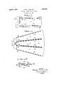
- Fig. 2 is a plan view of the auditorium having a fan or wedge shape.
- Fig. 3 is a detailed sketch of means for separating certain sound reproducing devices.
- an auditorium 5 has a stage or dais 6.
- Microphones 8 and 9 may be placed in the front-center portion of the stage, either suspended from above or located in. the footlights, if the stage has such a lighting arrangement. They also may be placed on standards if used in a tempora capacity.
- the microphone 8 is connecte with an amplifier 10, the output of which is fed into a series of loud speakers 12.
- the microphone 9 is connected to amplifier 11, the output of which is fed into a series of loud speakers 13.
- the loud speakers 12 and 13 may be connected to the amplifier electrically in series or in parallel, so that each speaker of the series 12 will project sound having the same phase at the same instant, while the receivers in the series 13 will have identical characteristics.
- These receivers may also be connected mechanically by means of a tensioned wire between cooperative driving units 15 for receivers 12, and driving units 16 for receivers 13. This mechanical arrangement is more fully disclosed in my copending application Ser. No. 453,987, filed May 20, 1930.
- source S on stage 6 is initiating sound waves, for instance, speech.
- These sound waves will be impinged on microphone 8, in advance of their reception at microphone 9, that is the Wave will be received at the microphones at different instances and, therefore, in differ ent phases, since the propagation of the wave between source 1 and microphones 8 and 9 is the-same.
- the sound produced in microphone 8, therefore, will be amplified and projected by the speakers into the auditorium 5 in the same phase as received at 8, While the sound projected into the auditorium 5 in the same phase as received at microphone 9.
- an auditorium 20 has a stage or dais 21 on which is positioned microphones 22 and 23. At 22 and 23 three microphones are shown connected in parallel, for the purose of detecting a larger amount of sound. 11 the views shown, these microphones will be placed one on top of the other so that the parallel connected microphones will receive sound in the same phase relationship. It will be observed that the auditorium 20 has been divided into three sections A, B and C, each section of which is arranged according to Fig. 1.
- a series of loud speakers 25 are associated binaurally with res ect to a series of loud speakers 26', a series 0 loud speakers 27 are associated binaurally with respect to a series of loud speakers 28; and a series vof loud speakers 29 are associated binaurally with respect to a series of loud speakers 30, in their respective sections A, B and C.
- the sound reproducers 26, 28 and 30 are connected in parallel with the microphones 23, and project sound received at microphones 23 in phase, while the sound reproducers 25, 27 and 29 are connected in parallel to the microphones 22 and project sound therefrom in phase. Therefore, a person located in the center of any of the sections A, B and C will receive the same binaural effect as explained above in Fig. 1.
- the reproducers 25 have an amplifier 35, while the reproducers 26 have an amplifier 36; reproducers 27 have an amplifier 37, reproducers 28 have an amplifier 38; reproducers 29 have an amplifier 39, and reproducers 30 have an amplifier 40.
- These speakers are in a position not to obstruct the view of the audience, and are preferably located in aisles about at the level of the seats. They may also be supported from the ceiling with the loud speakers projecting at a downward angle. Between sections A and B, and sections B and C, separating reproducers 26 and 27 and reproducers 28 and 29-are shown baffle or absorption partitions 4:2 and 43, respectively.
- these partitions are shown at 44, separating the loud speakers 45 and L6 which are on opposite sides thereof.
- the partition 44 will be of sound absorbing material such as celatex or cloth, if the loud speakers are located a distance in front thereof, while this partition may constitute a bafile board of wood or metal if the speakers are immediately adjacent thereto, the partition serving, therefore, as a reflector of sound.
- Whichever type of partition is to be used depends entirely upon the acoustics of the auditorium in which the installation is to be made. For outdoor installations, however, .it is desirable to have the partition in the form of a bafile board to aid the projection of sound by the reproducers.
- the near microphone will receive sound at a higher energy level than the far microphone.
- This amplitude difference when presented by the difference in volume output of the opposing speakers, will augment the phase differential and increase the binaural efl'ect.
- the binaural effect will be maintained inasmuch as the radiation angle will include more of the distant speakers. In other words, sound from a larger number of speakers farther away will be heard in one ear, and sound from a lesser number of thenear speakers will be heard in the other car, so that if the output amplitude of sound from the speakers is equal originally, it will remain so to listeners in substantially any position.
- This invention contemplates systems providing binaural eifects for public address systems, radio broadcasting either wired or space.
- the invention has been disclosed in one particular embodiment it is sub j ect to many modifications within the scope of the appended claims.
- a plurality of microphones for detecting sound in difierent phase relationships, a plurality of loud speakers arranged substantially in a plurality of radial rows and connected to said microphones, and an operating medium between two centrally disposed rows of said speakers, said rows of speakers forming sound fields having similar binaural aspects.
- a sound projection system a definite space in which sound is to be projected, a series of separating mediums dividing said space into substantially equal areas, a series of interconnected speakers ositioned on the same relative sides of said separating mediums and projecting sound in one direction, a second series of interconnected speakers positioned on the other sides of said separating mediums projecting sound in the opposite direction, and a third series of speakers on the boundaries of said area projecting sound toward a line in thecenter of said area, the series of speakers projecting sound in the same direction being connected to one microphone, while the speakersprojecting sound in substantially the opposite direction are connected to a second microphone physically displaced with res ect to said first microphone, both microp ones detecting the same sound source simultaneously.
Landscapes
- Physics & Mathematics (AREA)
- Engineering & Computer Science (AREA)
- Acoustics & Sound (AREA)
- Signal Processing (AREA)
- Circuit For Audible Band Transducer (AREA)
- Stereophonic System (AREA)
- Soundproofing, Sound Blocking, And Sound Damping (AREA)
Description
April 5, 1932. A. MCL. NICOLSON 1,852,624
BINAURAL PUBLIC ADDRESS SYSTEM Filed May 16, 1950 6- .5 A A A is? .83 H v v 7 I 'INVENTOR A/emnder' MLaan N/calson.
M Z M ATTORNEY Patented Apr. 5, 1932 UNITED STATES PATENT OFFICE- MGLEAN NIGOLSON, OF NEW YORK, N. Y., ASSIGNOR 'I'O COMMUNICATION PATENTS, ING, OF NEW YORK, N. Y., A CORPORATION OF DELAWARE IBIN'AURAL PUBLIC Anmmss SYSTEM Application filed May 16, 1930. Serial No. 453,003.
This invention relates to a method of and apparatus for the transmission of sound, and particularly to systems for the transmission of sounds having directional or binaural effects.
Another ob ect of this invention is to transm-it sound from a single source with an electrical system which will reproduce the sound In its proper phase relationship.
Another object of the invention is to am- L plify sound in a large auditorium or outdoors,
so as to provide to the listeners thereof in substantially every location, the directional efiect.
It is well known that the direction from which a source of sound is propagated is determinable because of the difference in phase of the sound Waves at two positions at unequal distances from the source, together with the difierence in volume at these. positions,
2 providingS the transmission medium is the same. A o for positions at equal distances the respective phase and amplitude relations are substantially the same.
These equal and unequal phase and amplitude relationships of a sound wave or waves impinging on the ears of a person, provide the sense of direction of the source. If the original phase displacement can be maintained throughout an electrical transmission system, and reproduced from properly positioned reproducing devices, the listener will properly place the source of sound. For instance, in a large auditorium or in the case of an outdoor presentation, in which several persons are speaking and a public address system is necessary to properly bring the voices to all listeners, if the reproduction of the speakers is directional, every listener will be presented with the program in perfect sound perspective. Especially if the voices are inaudible without loud speakers, the present invention will lessen confusion as to persons speaking at any particular time.
The present invention contemplates using microphones with their associated amplifiers fully understood'by reference to the accompanying drawings, in which:
Figure 1 is a diagrammatic sketch of an oblong auditorium.
Fig. 2 is a plan view of the auditorium having a fan or wedge shape.
Fig. 3 is a detailed sketch of means for separating certain sound reproducing devices.
Referring particularly to Fig. 1, an auditorium 5 has a stage or dais 6. Microphones 8 and 9 may be placed in the front-center portion of the stage, either suspended from above or located in. the footlights, if the stage has such a lighting arrangement. They also may be placed on standards if used in a tempora capacity. The microphone 8 is connecte with an amplifier 10, the output of which is fed into a series of loud speakers 12. The microphone 9 is connected to amplifier 11, the output of which is fed into a series of loud speakers 13.
The loud speakers 12 and 13 may be connected to the amplifier electrically in series or in parallel, so that each speaker of the series 12 will project sound having the same phase at the same instant, while the receivers in the series 13 will have identical characteristics. These receivers may also be connected mechanically by means of a tensioned wire between cooperative driving units 15 for receivers 12, and driving units 16 for receivers 13. This mechanical arrangement is more fully disclosed in my copending application Ser. No. 453,987, filed May 20, 1930.
To obtain the binaural effect with the system in Fig. 1, We may assume source S on stage 6 is initiating sound waves, for instance, speech. These sound waves will be impinged on microphone 8, in advance of their reception at microphone 9, that is the Wave will be received at the microphones at different instances and, therefore, in differ ent phases, since the propagation of the wave between source 1 and microphones 8 and 9 is the-same. The sound produced in microphone 8, therefore, will be amplified and projected by the speakers into the auditorium 5 in the same phase as received at 8, While the sound projected into the auditorium 5 in the same phase as received at microphone 9. A person, therefore, sitting in the center of the auditorium facing the stage and hearing the reception in both ears from the loud speakers 12 and 13, will be conscious of a sound originating from the right hand side of the stage. If the source is as at S the ekact reverse phase relationship will be obtained, and a listener in the center of the auditorium will be conscious of the sound arising at the left hand portion of the stage. Of course, a sound initiating from the source S will reach the microphones at the same instant and in phase, and will be projected by loud speakers 12 and 13 in phase. It is realized, of course, that this effect may not be as positive for every location of the person with respect to the loud speakers, but this condition is substantially overcome by the serial arrangement of the speakers and the construction shown in Fig. 2.
In Fig. 2 an auditorium 20. has a stage or dais 21 on which is positioned microphones 22 and 23. At 22 and 23 three microphones are shown connected in parallel, for the purose of detecting a larger amount of sound. 11 the views shown, these microphones will be placed one on top of the other so that the parallel connected microphones will receive sound in the same phase relationship. It will be observed that the auditorium 20 has been divided into three sections A, B and C, each section of which is arranged according to Fig. 1. A series of loud speakers 25 are associated binaurally with res ect to a series of loud speakers 26', a series 0 loud speakers 27 are associated binaurally with respect to a series of loud speakers 28; and a series vof loud speakers 29 are associated binaurally with respect to a series of loud speakers 30, in their respective sections A, B and C. The sound reproducers 26, 28 and 30 are connected in parallel with the microphones 23, and project sound received at microphones 23 in phase, while the sound reproducers 25, 27 and 29 are connected in parallel to the microphones 22 and project sound therefrom in phase. Therefore, a person located in the center of any of the sections A, B and C will receive the same binaural effect as explained above in Fig. 1. The reproducers 25 have an amplifier 35, while the reproducers 26 have an amplifier 36; reproducers 27 have an amplifier 37, reproducers 28 have an amplifier 38; reproducers 29 have an amplifier 39, and reproducers 30 have an amplifier 40.
The location of these speakers are in a position not to obstruct the view of the audience, and are preferably located in aisles about at the level of the seats. They may also be supported from the ceiling with the loud speakers projecting at a downward angle. Between sections A and B, and sections B and C, separating reproducers 26 and 27 and reproducers 28 and 29-are shown baffle or absorption partitions 4:2 and 43, respectively.
Referring specifically to Fig. 3, these partitions are shown at 44, separating the loud speakers 45 and L6 which are on opposite sides thereof. The partition 44 will be of sound absorbing material such as celatex or cloth, if the loud speakers are located a distance in front thereof, while this partition may constitute a bafile board of wood or metal if the speakers are immediately adjacent thereto, the partition serving, therefore, as a reflector of sound. Whichever type of partition is to be used, depends entirely upon the acoustics of the auditorium in which the installation is to be made. For outdoor installations, however, .it is desirable to have the partition in the form of a bafile board to aid the projection of sound by the reproducers.
In the above arrangement, it is to be noted that the near microphone will receive sound at a higher energy level than the far microphone. This amplitude difference when presented by the difference in volume output of the opposing speakers, will augment the phase differential and increase the binaural efl'ect. Furthermore, if a listener is positioned nearer one series of speakers than the opposite series, the binaural effect will be maintained inasmuch as the radiation angle will include more of the distant speakers. In other words, sound from a larger number of speakers farther away will be heard in one ear, and sound from a lesser number of thenear speakers will be heard in the other car, so that if the output amplitude of sound from the speakers is equal originally, it will remain so to listeners in substantially any position.
This invention contemplates systems providing binaural eifects for public address systems, radio broadcasting either wired or space. Although the invention has been disclosed in one particular embodiment it is sub j ect to many modifications within the scope of the appended claims.
What is claimed is:
1. In a public address system, a plurality of microphones for detecting sound in difierent phase relationships, a plurality of loud speakers arranged substantially in a plurality of radial rows and connected to said microphones, and an operating medium between two centrally disposed rows of said speakers, said rows of speakers forming sound fields having similar binaural aspects.v
2. Ina sound projection system, a definite space in which sound is to be projected, a series of separating mediums dividing said space into substantially equal areas, a series of interconnected speakers ositioned on the same relative sides of said separating mediums and projecting sound in one direction, a second series of interconnected speakers positioned on the other sides of said separating mediums projecting sound in the opposite direction, and a third series of speakers on the boundaries of said area projecting sound toward a line in thecenter of said area, the series of speakers projecting sound in the same direction being connected to one microphone, while the speakersprojecting sound in substantially the opposite direction are connected to a second microphone physically displaced with res ect to said first microphone, both microp ones detecting the same sound source simultaneously.
3. A sound projection system in accordance v with claim 2, in which said dividing mediums serve as sound reflecting surfaces.
4. The art of producing natural sound effects for large audiences from sound reproducing devices comprising dividing the area occupied by said audience into divisions by sound reflecting partitions, rality of series of loud speakers on the same relative sides of said partitions, arran 'ng a second plurality of series of loud spea ers on the opposite sides of said partitions, and energizing each plurality of series from a set of binaurally arranged microphones.
Witness my hand this 14th day of May, 1930, at'Newark, in the county of Essex and State of New Jersey ALEXANDER MGLEAN NICOLSON.
arranging a plu-
Priority Applications (1)
| Application Number | Priority Date | Filing Date | Title |
|---|---|---|---|
| US453003A US1852624A (en) | 1930-05-16 | 1930-05-16 | Binaural public address system |
Applications Claiming Priority (1)
| Application Number | Priority Date | Filing Date | Title |
|---|---|---|---|
| US453003A US1852624A (en) | 1930-05-16 | 1930-05-16 | Binaural public address system |
Publications (1)
| Publication Number | Publication Date |
|---|---|
| US1852624A true US1852624A (en) | 1932-04-05 |
Family
ID=23798837
Family Applications (1)
| Application Number | Title | Priority Date | Filing Date |
|---|---|---|---|
| US453003A Expired - Lifetime US1852624A (en) | 1930-05-16 | 1930-05-16 | Binaural public address system |
Country Status (1)
| Country | Link |
|---|---|
| US (1) | US1852624A (en) |
Cited By (6)
| Publication number | Priority date | Publication date | Assignee | Title |
|---|---|---|---|---|
| US2419894A (en) * | 1945-08-01 | 1947-04-29 | Bendix Aviat Corp | Acoustic system for uniform distribution of sound |
| US2481576A (en) * | 1944-07-14 | 1949-09-13 | Hartford Nat Bank & Trust Co | Device for stereophonic sound transmission in two channels |
| US2542663A (en) * | 1948-04-30 | 1951-02-20 | Rca Corp | Acoustic studio with variable reverberation time |
| US2821878A (en) * | 1954-03-15 | 1958-02-04 | George R Stibitz | Stereophonic organ |
| US2826112A (en) * | 1953-05-29 | 1958-03-11 | Warner Bros | Stereoscopic picture and stereophonic sound systems |
| US3039346A (en) * | 1956-05-14 | 1962-06-19 | Baldwin Piano Co | Sound distribution system |
-
1930
- 1930-05-16 US US453003A patent/US1852624A/en not_active Expired - Lifetime
Cited By (6)
| Publication number | Priority date | Publication date | Assignee | Title |
|---|---|---|---|---|
| US2481576A (en) * | 1944-07-14 | 1949-09-13 | Hartford Nat Bank & Trust Co | Device for stereophonic sound transmission in two channels |
| US2419894A (en) * | 1945-08-01 | 1947-04-29 | Bendix Aviat Corp | Acoustic system for uniform distribution of sound |
| US2542663A (en) * | 1948-04-30 | 1951-02-20 | Rca Corp | Acoustic studio with variable reverberation time |
| US2826112A (en) * | 1953-05-29 | 1958-03-11 | Warner Bros | Stereoscopic picture and stereophonic sound systems |
| US2821878A (en) * | 1954-03-15 | 1958-02-04 | George R Stibitz | Stereophonic organ |
| US3039346A (en) * | 1956-05-14 | 1962-06-19 | Baldwin Piano Co | Sound distribution system |
Similar Documents
| Publication | Publication Date | Title |
|---|---|---|
| FI81471B (en) | HOEGTALARE GIVANDE ETT TREDIMENSIONELLT STEREOLJUDINTRYCK. | |
| US2114680A (en) | System for the reproduction of sound | |
| Camras | Approach to recreating a sound field | |
| US5809150A (en) | Surround sound loudspeaker system | |
| US3892624A (en) | Stereophonic sound reproducing system | |
| JP2575318B2 (en) | Theater speaker and screen device | |
| US4256922A (en) | Stereophonic effect speaker arrangement | |
| US3125181A (en) | pawlowski | |
| US1932343A (en) | Radio loud speaker cabinet | |
| Schroeder | Improved Quasi‐Stereophony and “Colorless” Artificial Reverberation | |
| CN102598718B (en) | For reproducing the amplifier system of the multi-channel sound of the acoustic image with improvement | |
| GB1484633A (en) | Stereophonic sound reproducing apparatus | |
| US3892917A (en) | Speaker system for multichannel stereosignal reproduction | |
| US3588355A (en) | Stereophonic loudspeaker system | |
| US4837825A (en) | Passive ambience recovery system for the reproduction of sound | |
| US4862508A (en) | Method for large-scale multiple source sound reinforcement | |
| US3065816A (en) | Stereophonic sound distributor | |
| US1852624A (en) | Binaural public address system | |
| US3759345A (en) | Stereophonic sound-reproducing system | |
| GB1572093A (en) | Omniphonic transducer system | |
| US2993557A (en) | Omnidirectional stereo system | |
| Fletcher | Auditory perspective-Basic requirements | |
| US2135610A (en) | Horn | |
| US2701025A (en) | High fidelity sound system | |
| JPH03169200A (en) | Television receiver |