US1852615A - Truck wheel - Google Patents
Truck wheel Download PDFInfo
- Publication number
- US1852615A US1852615A US131150A US13115026A US1852615A US 1852615 A US1852615 A US 1852615A US 131150 A US131150 A US 131150A US 13115026 A US13115026 A US 13115026A US 1852615 A US1852615 A US 1852615A
- Authority
- US
- United States
- Prior art keywords
- wheel
- felloe
- arch
- rim
- seat
- Prior art date
- Legal status (The legal status is an assumption and is not a legal conclusion. Google has not performed a legal analysis and makes no representation as to the accuracy of the status listed.)
- Expired - Lifetime
Links
- 238000010276 construction Methods 0.000 description 3
- 230000009977 dual effect Effects 0.000 description 3
- 229910001208 Crucible steel Inorganic materials 0.000 description 1
- 229910000831 Steel Inorganic materials 0.000 description 1
- 239000002184 metal Substances 0.000 description 1
- 238000013021 overheating Methods 0.000 description 1
- 230000002787 reinforcement Effects 0.000 description 1
- 238000007790 scraping Methods 0.000 description 1
- 239000007787 solid Substances 0.000 description 1
- 239000010959 steel Substances 0.000 description 1
Images
Classifications
-
- B—PERFORMING OPERATIONS; TRANSPORTING
- B60—VEHICLES IN GENERAL
- B60B—VEHICLE WHEELS; CASTORS; AXLES FOR WHEELS OR CASTORS; INCREASING WHEEL ADHESION
- B60B11/00—Units comprising multiple wheels arranged side by side; Wheels having more than one rim or capable of carrying more than one tyre
- B60B11/06—Wheels with more than one rim mounted on a single wheel body
Definitions
- This invention relates to truck wheels, particularly of the type illustrated in my Patent No.1,640,338, granted August 23, 1927.
- Thesetruck wheels are intended to be conf 5 structed of cast metal and preferably of cast steel. They are intended to carry dual tires.
- ,y l0 wheels of more or less solid or disc form have p 20 which will facilitate the application of the inboard and outboard tires, and particularly to construct the wheel so as to facilitate access to the bolts that secure the inboard tire in place.
- a further object of the invention is to improve the general construction of wheels of this typeby increasing their strength Iparticularly at the rim between the felloes.
- the invention consists in the novel parts and combination of parts to be described hereinafter, all of which contribute to produce an eiicient truck wheel. ⁇
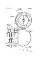
- Figure 1 is a side elevation and section on the line 1-1 of Fig. 2.
- Figure 2 is a section taken on the line 2 2 of Fig. 1.
- Figure 3 is a side elevation of the tire rim-seat removed from the wheel, with the left portion of the seat broken away.
- a brake drum 6 may be attached on the inner face of the hub portion of the wheel.
- I illustrate a separate hub 7 which is secured in the central openingor bore 8 of the wheel.
- I construct the outboard felloe with a substantially cylindrical outer face 15, and at the inboard end of this felloe I provide an outwardly projecting circumferential edge 16.
- On this edge I provide a rim-seat 17 which is in the form of a ring (see Fig. 3).
- This ring has a cylindrical inner face 18 to be received over the cylindrical edge 16, and in addition to this, it has on its outboard edge an inwardly projecting narrow flange 19.
- This flange cooperates with the face 18 to form an angle and shoulder to receive the projecting edge.
- This flange operates to impart inboard thrust of the tire-rim to the projecting edge 16.
- the rim-seat 17 On its outer sid-e, the rim-seat 17 is provided with an inclined seat face 2O which receives the corresponding seat face on the outboard tire-rim 14.
- the inner edge of the flange 19 is located at a point out of contact with the cylindrical face of the outboard felloe.
- the rim-seat 17 is put in place by slipping it over the outboard felloe 5.
- the rim-seat 17 can be slipped into position Without this flange scraping along the face of the felloe, and hence, this seat can be put in place without gathering grit, which would prevent it from seating properly on l the projecting edge 16.
- I provide the arch portion 3 of the wheel with a plurality of large openings 25.
- I have shown six of these openings. They are Y relatively large so as t0v insure an ample circulation of air through them.
- I provide the outer or concave side of the arch 3 with a plurality of webs 26 which virtually constitute the spokes of this wheel. These webs are preferably disposed substantially in planes radiating from the axis of the wheel. They are of course cast integrally with the wheel.
- the studs 13 for the inboard tire rim are located substantially midway between the studs 23 for the inboard tire rim (measuring circumferentially) and this brings the studs 13 opposite the openings 25, so that the nuts of these bolts are accessible to a wrench inserted through the openings.
- openings 25 not only pass through the outer wall of the arch 3 but they also pass through the inner wall, as indicated at the point 27 at the lower edge of F ig. 24. In this way, I provide an ample circulation of air into the space 28 surrounding the brake drum 6- This is veryeffective in preventing overheating of the ⁇ brake drums.
- the webs 26 operate as blades when the wheel is in use to forcethe air outwardly between the felloes, and this tends to produce an air current at the outer side of the wheel moving substantially parallel with the axis of the wheel. This air current of course will have the ef- Y fe'ct of passing a considerable quantity of air through the inboard side of the arch 3 Aso as to pass around the brake drum.
- I provide the outboard felloe 5 with integral bosses or posts 5a which extend out from the arch 3 to the outer edge of this felloe, and on these bosses the studs 23 are secured.
- the outer faces of these bosses form seats for the lugs 22 flush with the outboard edge of the felloe, which is desirable, and furthermore, they act as reinforcements for the felloe.
- the outer faces of the felloes are provided with one or more lugs.
- a lug or lugs 29 may be provided on the inboard felloe (see Fig. 2), and a similar lug or lugs 30 may be provided on the outboard felloe.
- the lugs 30 would of course interfere with the passing of the tire rim-seat 17 over the felloe as suggested, but in order to avoid this, I form this rim-seat or ring 17 as a split ring. In the present instance, there may be two of the lugs 30 disposed at a slight distance apart on the face ofthe felloe, in which case I provide the rim-seat with a gap 3:1 of considerable width, sufficient to clean the.' lugs 30 when the rim-seat is put in place.
- a truck wheel to carry dual tires having a hub portion with two webs disposed apart with an arch integrally connecting the said webs, and having a felloe. projecting' laterally from, each side of' the arch, said archshaped portion having its concave side disposed outwardlyV with transverse webs extending across the arch on its concave side, and disposed substantially in planes radiating from the axis ofthe wheel, said archshaped portion having aV plurality ofv openings therethrough tov admitf air into the space between Vthe felloes, said last-named webs operating tojforce the airoutwardily between the felloes when the wheel is in use.
- a truck w-heel'nto carry dual tires, having a hub portion with two. webs disposed apart, anarch-shapedr outer portion'connected integrally to, the said webs and having a felloe-projecting laterally. from each,l side of the arch-shaped portion, Said arch-Shaped portion having its concave; side disposed ,outwardly with transverseintegral webs extending across the concave side of the arch-shaped portion, a brake-drum attached to the inner face of the hub-portion, said arch-shaped portion having a plurality of openings therethrough on its outboard side to admit air into the space between the felloes and into the space surrounding the brake drum, said transverse webs operating to force the air outwardly between the elloes when the wheel is in use, and to develop an air current through the wheel into the space surrounding the brake-drum.
Landscapes
- Engineering & Computer Science (AREA)
- Mechanical Engineering (AREA)
- Tires In General (AREA)
Description
April 5, 1932. L.V D. KAY 1,852,615
TRUCK WHEEL Filed Aug. 24, 1926 Llolqd.; D. Kay
l a@ ww Patented Apr. 5, 1932 UNITED STATES PATENT OFFICE LLOYD D. KAY, OF LOS ANGELES, CALIFORNIA, ASSIGNOR TO KAY-IBRUNNER STEEL PRODUCTS INC., A. CORPORATION TRUCK WHEEL Application led August 24, 1926. Serial No. 131,150.
This invention relates to truck wheels, particularly of the type illustrated in my Patent No.1,640,338, granted August 23, 1927. Thesetruck wheels .are intended to be conf 5 structed of cast metal and preferably of cast steel. They are intended to carry dual tires.
By reason of the large size of the tires used on such wheels, the actual diameter "of the wheel body has become much reduced, and
,y l0 wheels of more or less solid or disc form have p 20 which will facilitate the application of the inboard and outboard tires, and particularly to construct the wheel so as to facilitate access to the bolts that secure the inboard tire in place.
provide a construction fora wheel of this type which will facilitate the circulation of V30. is usually cut off by the disc of the wheel.
A further object of the invention is to improve the general construction of wheels of this typeby increasing their strength Iparticularly at the rim between the felloes.
Further objects of the invention will appear hereinafter.
The invention consists in the novel parts and combination of parts to be described hereinafter, all of which contribute to produce an eiicient truck wheel.`
A preferred embodiment ofthe invention is described in the following specification, While the broad scope ofthe invention is i p pointed out in the appended claims.
' One of the objects of this invention is to In the drawings:
Figure 1 is a side elevation and section on the line 1-1 of Fig. 2.
Figure 2 is a section taken on the line 2 2 of Fig. 1.
Figure 3 is a side elevation of the tire rim-seat removed from the wheel, with the left portion of the seat broken away. i
In practicing the invention, I construct the partial hub portion of the wheel of two discs or Webs 1 which are disposed apart and connected at the nave of the wheel by a plurality of circumferentially disposed Webs or posts 2 (see Fig. 1). These webs 1 at their outer edges connect integrally with an arch-shaped portion or arch 3 of the wheel, which is disposed with its concave side outwardly. At veach side or edge of the arch 3, the felloes of the wheel are carried, and these are formed integrally with the arch. In the illustration, l
indicates the inboard felloe and 5 indicates the outboard felloe. On the inner face of the hub portion of the wheel, a brake drum 6 may be attached. In the present wheel, I illustrate a separate hub 7 which is secured in the central openingor bore 8 of the wheel.
On Ythe inboard edge of the inboard felloe 4;, I provide an inclined rim-seat 9 in the usual manner, to receive the inboard tirerim 10 which is indicated in dotted outline. This tire-rim may be held in place by means of the usual wedge ring 11, backed upby clam-ps or clips 12 received on studs 13.
In order to provide a seat for the outboard tire-rim 14C, indicated in dotted outline, I construct the outboard felloe with a substantially cylindrical outer face 15, and at the inboard end of this felloe I provide an outwardly projecting circumferential edge 16. On this edge I provide a rim-seat 17 which is in the form of a ring (see Fig. 3). This ring has a cylindrical inner face 18 to be received over the cylindrical edge 16, and in addition to this, it has on its outboard edge an inwardly projecting narrow flange 19. This flange cooperates with the face 18 to form an angle and shoulder to receive the projecting edge. This flange operates to impart inboard thrust of the tire-rim to the projecting edge 16.
On its outer sid-e, the rim-seat 17 is provided with an inclined seat face 2O which receives the corresponding seat face on the outboard tire-rim 14. The inner edge of the flange 19 is located at a point out of contact with the cylindrical face of the outboard felloe. The rim-seat 17 is put in place by slipping it over the outboard felloe 5. By reason of the fact. that the inner edge of the flange 19 is removedfrom the outer face of the felloe, the rim-seat 17 can be slipped into position Without this flange scraping along the face of the felloe, and hence, this seat can be put in place without gathering grit, which would prevent it from seating properly on l the projecting edge 16.
After the 'outboard tire-rim 14 has been put in place in this way, it is secured with the usual wedge ring 21 at its outer edge held in place by clamps or clips 22 received 0n studs 23 in the usual manner.
In order to provide for circulation of air into the space 24 between the tires carried on the tire-rims 10 and 14, I provide the arch portion 3 of the wheel with a plurality of large openings 25. In the present wheel I have shown six of these openings. They are Y relatively large so as t0v insure an ample circulation of air through them. In order to increase the strength of the wheel and also to provide for forcing this air outwardly, I provide the outer or concave side of the arch 3 with a plurality of webs 26 which virtually constitute the spokes of this wheel. These webs are preferably disposed substantially in planes radiating from the axis of the wheel. They are of course cast integrally with the wheel.
The studs 13 for the inboard tire rim are located substantially midway between the studs 23 for the inboard tire rim (measuring circumferentially) and this brings the studs 13 opposite the openings 25, so that the nuts of these bolts are accessible to a wrench inserted through the openings.
These openings 25 not only pass through the outer wall of the arch 3 but they also pass through the inner wall, as indicated at the point 27 at the lower edge of F ig. 24. In this way, I provide an ample circulation of air into the space 28 surrounding the brake drum 6- This is veryeffective in preventing overheating of the` brake drums. The webs 26 operate as blades when the wheel is in use to forcethe air outwardly between the felloes, and this tends to produce an air current at the outer side of the wheel moving substantially parallel with the axis of the wheel. This air current of course will have the ef- Y fe'ct of passing a considerable quantity of air through the inboard side of the arch 3 Aso as to pass around the brake drum.
As shown most clearly in Figure 2, I provide the outboard felloe 5 with integral bosses or posts 5a which extend out from the arch 3 to the outer edge of this felloe, and on these bosses the studs 23 are secured. The outer faces of these bosses form seats for the lugs 22 flush with the outboard edge of the felloe, which is desirable, and furthermore, they act as reinforcements for the felloe.
It will be `noted that by reasony of the laterally displaced po-sition of the arch 3 as illustrated in the drawings, the plane of the center line of the arch is 'displaced in an outboard direction out of line with the webs 1 of the In order to prevent the tire rims from creeping or working around on the felloes, the outer faces of the felloes are provided with one or more lugs. In the illustration, a lug or lugs 29 may be provided on the inboard felloe (see Fig. 2), and a similar lug or lugs 30 may be provided on the outboard felloe. The lugs 30 would of course interfere with the passing of the tire rim-seat 17 over the felloe as suggested, but in order to avoid this, I form this rim-seat or ring 17 as a split ring. In the present instance, there may be two of the lugs 30 disposed at a slight distance apart on the face ofthe felloe, in which case I provide the rim-seat with a gap 3:1 of considerable width, sufficient to clean the.' lugs 30 when the rim-seat is put in place.
The rimseat 17 and thel oo-ordinated construction of the wheel as covered by claims 1 to 3 of my application as filed, is my invention, and I reserve the right, and intend to file a separate application for patent covering the same.
What I claim is 1. A truck wheel to carry dual tires, having a hub portion with two webs disposed apart with an arch integrally connecting the said webs, and having a felloe. projecting' laterally from, each side of' the arch, said archshaped portion having its concave side disposed outwardlyV with transverse webs extending across the arch on its concave side, and disposed substantially in planes radiating from the axis ofthe wheel, said archshaped portion having aV plurality ofv openings therethrough tov admitf air into the space between Vthe felloes, said last-named webs operating tojforce the airoutwardily between the felloes when the wheel is in use.
2. A truck w-heel'nto carry dual tires, having a hub portion with two. webs disposed apart, anarch-shapedr outer portion'connected integrally to, the said webs and having a felloe-projecting laterally. from each,l side of the arch-shaped portion, Said arch-Shaped portion having its concave; side disposed ,outwardly with transverseintegral webs extending across the concave side of the arch-shaped portion, a brake-drum attached to the inner face of the hub-portion, said arch-shaped portion having a plurality of openings therethrough on its outboard side to admit air into the space between the felloes and into the space surrounding the brake drum, said transverse webs operating to force the air outwardly between the elloes when the wheel is in use, and to develop an air current through the wheel into the space surrounding the brake-drum.
Signed at Los Angeles, California, this 6th day of August, 1926.
LLOYD D. KAY.
Priority Applications (1)
| Application Number | Priority Date | Filing Date | Title |
|---|---|---|---|
| US131150A US1852615A (en) | 1926-08-24 | 1926-08-24 | Truck wheel |
Applications Claiming Priority (1)
| Application Number | Priority Date | Filing Date | Title |
|---|---|---|---|
| US131150A US1852615A (en) | 1926-08-24 | 1926-08-24 | Truck wheel |
Publications (1)
| Publication Number | Publication Date |
|---|---|
| US1852615A true US1852615A (en) | 1932-04-05 |
Family
ID=22448117
Family Applications (1)
| Application Number | Title | Priority Date | Filing Date |
|---|---|---|---|
| US131150A Expired - Lifetime US1852615A (en) | 1926-08-24 | 1926-08-24 | Truck wheel |
Country Status (1)
| Country | Link |
|---|---|
| US (1) | US1852615A (en) |
Cited By (1)
| Publication number | Priority date | Publication date | Assignee | Title |
|---|---|---|---|---|
| US2642316A (en) * | 1949-10-12 | 1953-06-16 | Antonio E Frandi | Automobile wheel mounting |
-
1926
- 1926-08-24 US US131150A patent/US1852615A/en not_active Expired - Lifetime
Cited By (1)
| Publication number | Priority date | Publication date | Assignee | Title |
|---|---|---|---|---|
| US2642316A (en) * | 1949-10-12 | 1953-06-16 | Antonio E Frandi | Automobile wheel mounting |
Similar Documents
| Publication | Publication Date | Title |
|---|---|---|
| US2249568A (en) | Demountable rim | |
| US1327607A (en) | Dual-tired wheel | |
| US1852615A (en) | Truck wheel | |
| US2259022A (en) | Vehicle wheel | |
| US2039554A (en) | Vehicle wheel for dual demountable rims | |
| US1928897A (en) | Truck wheel | |
| US1984048A (en) | Metal wheel | |
| US2049268A (en) | Safety attachment for truck wheels | |
| US2252163A (en) | Wheel | |
| US2486569A (en) | Wheel | |
| US1923811A (en) | Wheel for motor vehicles | |
| US1966826A (en) | Vehicle artillery wheel | |
| US1945277A (en) | Dual tired truck wheel | |
| US1163736A (en) | Rim for vehicle-wheels. | |
| US2386030A (en) | Dual wheeled vehicle | |
| US2117926A (en) | Metal wheel | |
| US1966823A (en) | Motor truck wheel | |
| US1473406A (en) | Vehicle wheel | |
| US2104565A (en) | Safety attachment for truck wheels | |
| US2719559A (en) | Dual wheel spacer bands | |
| US1666703A (en) | Heavy-duty disk-wheel structure | |
| US1584845A (en) | Automobile wheel | |
| US1851187A (en) | Vehicle wheel | |
| US1640339A (en) | Dual-tired wheel | |
| US1690981A (en) | Vehicle wheel rim |