US1852612A - Cranking shaft driven starter - Google Patents
Cranking shaft driven starter Download PDFInfo
- Publication number
- US1852612A US1852612A US425794A US42579430A US1852612A US 1852612 A US1852612 A US 1852612A US 425794 A US425794 A US 425794A US 42579430 A US42579430 A US 42579430A US 1852612 A US1852612 A US 1852612A
- Authority
- US
- United States
- Prior art keywords
- shaft
- pinion
- gear wheel
- starter
- engine
- Prior art date
- Legal status (The legal status is an assumption and is not a legal conclusion. Google has not performed a legal analysis and makes no representation as to the accuracy of the status listed.)
- Expired - Lifetime
Links
Images
Classifications
-
- F—MECHANICAL ENGINEERING; LIGHTING; HEATING; WEAPONS; BLASTING
- F02—COMBUSTION ENGINES; HOT-GAS OR COMBUSTION-PRODUCT ENGINE PLANTS
- F02N—STARTING OF COMBUSTION ENGINES; STARTING AIDS FOR SUCH ENGINES, NOT OTHERWISE PROVIDED FOR
- F02N15/00—Other power-operated starting apparatus; Component parts, details, or accessories, not provided for in, or of interest apart from groups F02N5/00 - F02N13/00
- F02N15/02—Gearing between starting-engines and started engines; Engagement or disengagement thereof
- F02N15/04—Gearing between starting-engines and started engines; Engagement or disengagement thereof the gearing including disengaging toothed gears
-
- Y—GENERAL TAGGING OF NEW TECHNOLOGICAL DEVELOPMENTS; GENERAL TAGGING OF CROSS-SECTIONAL TECHNOLOGIES SPANNING OVER SEVERAL SECTIONS OF THE IPC; TECHNICAL SUBJECTS COVERED BY FORMER USPC CROSS-REFERENCE ART COLLECTIONS [XRACs] AND DIGESTS
- Y10—TECHNICAL SUBJECTS COVERED BY FORMER USPC
- Y10T—TECHNICAL SUBJECTS COVERED BY FORMER US CLASSIFICATION
- Y10T74/00—Machine element or mechanism
- Y10T74/13—Machine starters
- Y10T74/138—Radial meshing
Definitions
- the object of this invention is the provision of a cranking shaft driven starter with the engine starting gear wheel in an electric motor driven starter.
- One feature of the invention consists in mounting a hand operated cranking shaft in association with the casing of an electric motor starter so that, by the instrumentality of intermediate gearing, said hand operating crank can drive the gear of the electr1c motor starter and through it start the engine.
- Another feature of the invention consists in the particular means for transmitting power from the hand operated shaft to the gear wheel of an electric motor starter.
- Another feature of the invention conslsts 1n the use of said mechanism of a floating starter gear which is movable into mesh with the electric motor starter gear and driven by a pinion driven by the hand operated shaft for driving the electric motor starter gear wheel for starting the engine.
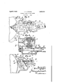
- Fig. 1 is a rear elevation of an electric motor driven starter casing with a hand operated starter means associated therewith and secured thereto, parts being broken away and parts shown by dotted lines.
- Fig. 2 is a central horizontal section on line 22 of Fig.
- Fig. 3 is a vertical transverse section on the line 3-3 of Fig. 2.
- said motor driven starter there is a casing 10 having a rear end plate 11 secured thereto by screws 12.
- said electric motor starter the power from'the electric motor is transmitted by means not here shown to drive a gear wheel 13, which gear wheel through said extension shaft drives the crank shaft of the engine and starts it.
- a gear chamber is provided by a lateral extension 14 of the casing of the electric motor starter as shown herein and in that extension there is mounted a shaft 15 transverse of the gear wheel 13 and parallel with its shaft, not shown.
- Said shaft is carried at one end in ballbearings 16 and in the other end in bearings 17 and on the outer end of said shaft there is a beveled gear 18 which is driven directly by a beveled gear 19 on the hand rotated shaft 20 and the said hand rotated shaft is flexible, as herein shown, and consists of the rotatable but otherwise fixed shaft 20 and the hand operated tubular section 21 pivoted to the former by the pin 22, as seen in Fig. 2.
- the particular construction of this shaft is not very material to this invention but the inner portion or section 20 is mounted in an additional housing 23 which is secured in the side of the extension casing 14 and which has on its rear side a removableplate 24 secured by screws 25.
- the section 20 of the hand crank shaft is mounted on two opposite ends of the housing 23, as seen in Fig. 2.
- the shaft 2120 By rotating the shaft 2120 the shaft 15 is driven and it carries a driving pinion 26 mounted in the same plane as the gear wheel 13, but not in mesh therewith.
- Power is transmitted from the pinion 26 to the gear wheel by the means shown in Fig. 3 that consists of a floating starting pinion 27 having a hub 28 that lies between a pair of plates 29.
- the plates 29 are mounted on and surround the shaft 15 on each'side of the driving pinion 26 and their free ends are longitudinally slotted at 30'to receivethe shaft 28 which is held in place by keys 31.
- the particular means for mounting the floating pinion 27 in said plates 29 is immaterial tothis invention.
- the floating pinion 27, however, is so mounted in said plates 29 that it is always in mesh with the driving pinion 26 and by swinging said plates 29 said starting pinion can be brought into mesh with the gear wheel 13, as seen in Fig. 3, for the purpose of starting the same.
- the movement of said starting pinion 27 into mesh with the gear wheel is effected positively by a push rod 32 that may extend out substantially parallel with the hand operated shaft to some convenient position.
- the rod 32 is returned after actuation by thespring 33 which surrounds said rod and lies between the extension casing 141 and the block 34 secured on said rod 32, as shown.
- a supplementary alternate means for actuating said push rod 32 consists in a lever 35 fulcrumed at its ends at 36 in the arm 37 from the casing 1a, and a draw bar 38 is connected to said lever so that when it is pulled it will actuate the rod 32 for the purpose of forcing the pinion 27 into mesh with the gear wheel 13.
- the operation consists in actuating the push rod 32 either directly or by pulling on the cord 38 to operate the lever 35 and through such instrumentality move the pinion 27 into mesh with the gear wheel 13.
- the shaft 2O21 is rotated and through the driving pinion 26 and floating pinion 27 said gear wheel 13 is driven and through this operation the crank shaft of the engine is turned and the engine started.
- the invention is not limited to the association of said hand operated means for driving the gear wheel of the electric motor starter as it might be used in driving the gear wheel mounted in connection with the crank shaft of the engine, as has been common in engine construction.
- Starting mechanism for an internal combustion engine including a gear wheel for starting the engine, a driving pinion, a start ing pinion, a carriage in which thestarting pinion is mounted and which is pivoted concentric with the axis of the driving pinion so the starting pinion will always be in mesh with the driving pinion and can be swung into mesh with the gear wheel to start the engine, hand drivenmeans for driving the driving pinion, and manually operable means adjacent to said hand driven means adapted to swing said starting pinion into mesh with said gear wheel.
- Starting mechanism for an internal combustion engine including a gear wheel for starting the engine, a casing therefor, a driving pinion, a starting pinion, a carriage in which the starting pinion is mounted and which is pivoted concentric with the axis of the driving pinion so the starting pinion will always be in mesh with the driving pinion and can be swung into mesh with the gear wheel to start the engine, a casing added to said gear wheel casing, a shaft in the added casing-on which the driving pinion is secured, a bevel gear on said added shaft, a flexible hand driven shaft extending into the added casing,and a bevel gear on the flexible shaft engaging said other bevel gear for driving the shaft on which the driving pinion is secured.
Landscapes
- Engineering & Computer Science (AREA)
- Chemical & Material Sciences (AREA)
- Combustion & Propulsion (AREA)
- Mechanical Engineering (AREA)
- General Engineering & Computer Science (AREA)
- Gear Transmission (AREA)
Description
April 1932- v. c. HODGES 1,852,612
CRANKING' SHAFT DRIVEN STARTER Filed Feb. 4, 1950 All/4 av/4 nub-w Invenzor,
"V'era C-Ifod es. 2 q f 1,23 filler-nays- Patented Apr, 5, 1932 1 UNITED STATES VERA C. HOIJGES, DE LOS ANGELES, CALIFORNIA CRANKING- SHAFT DRIVEN STARTER Application filed. February 4, 1930. Serial No. 425,794.
The object of this invention is the provision of a cranking shaft driven starter with the engine starting gear wheel in an electric motor driven starter.
It has been common heretofore to have hand cranking means for automobile engines and also electric motor starters for such engines, but said hand and electric starting means havebeen' independent of each other.
10 In this invention they are assembled together in a practical way so that it is more compact and safer, particularly for airplane use. If the electric starter fails the hand starter can be employed through a part of the electric starter mechanism. r
The general combination of the above mentioned mechanism is shown and claimed by me in another application filed Feb. 3, 1930, Serial Number 425,628, on starter for internal combustion engines.
One feature of the invention consists in mounting a hand operated cranking shaft in association with the casing of an electric motor starter so that, by the instrumentality of intermediate gearing, said hand operating crank can drive the gear of the electr1c motor starter and through it start the engine.
Another feature of the invention consists in the particular means for transmitting power from the hand operated shaft to the gear wheel of an electric motor starter. Another feature of the invention conslsts 1n the use of said mechanism of a floating starter gear which is movable into mesh with the electric motor starter gear and driven by a pinion driven by the hand operated shaft for driving the electric motor starter gear wheel for starting the engine.
The details of this invention will be more fully understood from the accompanying drawings and the following description and claims.
In the drawings:
Fig. 1 is a rear elevation of an electric motor driven starter casing with a hand operated starter means associated therewith and secured thereto, parts being broken away and parts shown by dotted lines. Fig. 2 is a central horizontal section on line 22 of Fig.
1, parts being omitted. Fig. 3 is a vertical transverse section on the line 3-3 of Fig. 2.
This invention is associated with and parts thereof are more fully shown in said prior application for a patent. As appears in said former application the electric motor starter is added to therear end of the engine and has its own shaft, which is an extension of the crank shaft of the engine and removably connected therewith, said arrangement, however, not being herein shown.
In said motor driven starter there is a casing 10 having a rear end plate 11 secured thereto by screws 12. In said electric motor starter the power from'the electric motor is transmitted by means not here shown to drive a gear wheel 13, which gear wheel through said extension shaft drives the crank shaft of the engine and starts it.
In order to operate said electric motor starter gear wheel and start the engine when the electric motor fails to function, or when for any other reason the same is desired, provision is made herein for accomplishing said result by hand.
To that end a gear chamber is provided by a lateral extension 14 of the casing of the electric motor starter as shown herein and in that extension there is mounted a shaft 15 transverse of the gear wheel 13 and parallel with its shaft, not shown.
Said shaft is carried at one end in ballbearings 16 and in the other end in bearings 17 and on the outer end of said shaft there is a beveled gear 18 which is driven directly by a beveled gear 19 on the hand rotated shaft 20 and the said hand rotated shaft is flexible, as herein shown, and consists of the rotatable but otherwise fixed shaft 20 and the hand operated tubular section 21 pivoted to the former by the pin 22, as seen in Fig. 2. The particular construction of this shaft, however, is not very material to this invention but the inner portion or section 20 is mounted in an additional housing 23 which is secured in the side of the extension casing 14 and which has on its rear side a removableplate 24 secured by screws 25.
The section 20 of the hand crank shaft is mounted on two opposite ends of the housing 23, as seen in Fig. 2. By rotating the shaft 2120 the shaft 15 is driven and it carries a driving pinion 26 mounted in the same plane as the gear wheel 13, but not in mesh therewith. Power is transmitted from the pinion 26 to the gear wheel by the means shown in Fig. 3 that consists of a floating starting pinion 27 having a hub 28 that lies between a pair of plates 29.
As shown in Fig. 2 the plates 29 are mounted on and surround the shaft 15 on each'side of the driving pinion 26 and their free ends are longitudinally slotted at 30'to receivethe shaft 28 which is held in place by keys 31. The particular means for mounting the floating pinion 27 in said plates 29 is immaterial tothis invention.
The floating pinion 27, however, is so mounted in said plates 29 that it is always in mesh with the driving pinion 26 and by swinging said plates 29 said starting pinion can be brought into mesh with the gear wheel 13, as seen in Fig. 3, for the purpose of starting the same. The movement of said starting pinion 27 into mesh with the gear wheel is effected positively by a push rod 32 that may extend out substantially parallel with the hand operated shaft to some convenient position.
I The rod 32 is returned after actuation by thespring 33 which surrounds said rod and lies between the extension casing 141 and the block 34 secured on said rod 32, as shown.
A supplementary alternate means for actuating said push rod 32 consists in a lever 35 fulcrumed at its ends at 36 in the arm 37 from the casing 1a, and a draw bar 38 is connected to said lever so that when it is pulled it will actuate the rod 32 for the purpose of forcing the pinion 27 into mesh with the gear wheel 13.
The operation consists in actuating the push rod 32 either directly or by pulling on the cord 38 to operate the lever 35 and through such instrumentality move the pinion 27 into mesh with the gear wheel 13. At the same time the shaft 2O21 is rotated and through the driving pinion 26 and floating pinion 27 said gear wheel 13 is driven and through this operation the crank shaft of the engine is turned and the engine started.
As soon as the engine is started said gear wheel 13 will kick the floating gear wheel 27 out of the way from the position shown in Fig. 3 to that shown in Fig. l, and it will be held in such disengaging position by the spring l0 shown in Fig. 3 which is connected at one end to the casing and at the other end to one of the plates 29 near the end in which the starting pinion 27 is mounted.
The invention, however, is not limited to the association of said hand operated means for driving the gear wheel of the electric motor starter as it might be used in driving the gear wheel mounted in connection with the crank shaft of the engine, as has been common in engine construction.
I claim as my invention:
1. Starting mechanism for an internal combustion engine including a gear wheel for starting the engine, a driving pinion, a start ing pinion, a carriage in which thestarting pinion is mounted and which is pivoted concentric with the axis of the driving pinion so the starting pinion will always be in mesh with the driving pinion and can be swung into mesh with the gear wheel to start the engine, hand drivenmeans for driving the driving pinion, and manually operable means adjacent to said hand driven means adapted to swing said starting pinion into mesh with said gear wheel.
2. Starting mechanism for an internal combustion engine including a gear wheel for starting the engine, a casing therefor, a driving pinion, a starting pinion, a carriage in which the starting pinion is mounted and which is pivoted concentric with the axis of the driving pinion so the starting pinion will always be in mesh with the driving pinion and can be swung into mesh with the gear wheel to start the engine, a casing added to said gear wheel casing, a shaft in the added casing-on which the driving pinion is secured, a bevel gear on said added shaft, a flexible hand driven shaft extending into the added casing,and a bevel gear on the flexible shaft engaging said other bevel gear for driving the shaft on which the driving pinion is secured.
'In witness whereof, Ihave hereunto affixed my signature.
VERA C. HODGES.
IZU
Priority Applications (1)
| Application Number | Priority Date | Filing Date | Title |
|---|---|---|---|
| US425794A US1852612A (en) | 1930-02-04 | 1930-02-04 | Cranking shaft driven starter |
Applications Claiming Priority (1)
| Application Number | Priority Date | Filing Date | Title |
|---|---|---|---|
| US425794A US1852612A (en) | 1930-02-04 | 1930-02-04 | Cranking shaft driven starter |
Publications (1)
| Publication Number | Publication Date |
|---|---|
| US1852612A true US1852612A (en) | 1932-04-05 |
Family
ID=23688070
Family Applications (1)
| Application Number | Title | Priority Date | Filing Date |
|---|---|---|---|
| US425794A Expired - Lifetime US1852612A (en) | 1930-02-04 | 1930-02-04 | Cranking shaft driven starter |
Country Status (1)
| Country | Link |
|---|---|
| US (1) | US1852612A (en) |
Cited By (2)
| Publication number | Priority date | Publication date | Assignee | Title |
|---|---|---|---|---|
| US2538147A (en) * | 1948-10-25 | 1951-01-16 | Deere Mfg Co | Starting device for internalcombustion engines |
| US2725751A (en) * | 1953-05-25 | 1955-12-06 | Continental Supply Company | Engine starter |
-
1930
- 1930-02-04 US US425794A patent/US1852612A/en not_active Expired - Lifetime
Cited By (2)
| Publication number | Priority date | Publication date | Assignee | Title |
|---|---|---|---|---|
| US2538147A (en) * | 1948-10-25 | 1951-01-16 | Deere Mfg Co | Starting device for internalcombustion engines |
| US2725751A (en) * | 1953-05-25 | 1955-12-06 | Continental Supply Company | Engine starter |
Similar Documents
| Publication | Publication Date | Title |
|---|---|---|
| US2475750A (en) | Model airplane starting unit | |
| US1852612A (en) | Cranking shaft driven starter | |
| US2547010A (en) | Aircraft engine starter | |
| US1009503A (en) | Self-starting device for internal-combustion engines. | |
| US1905836A (en) | Engine starter | |
| US1768083A (en) | Engine-starting mechanism | |
| US1363003A (en) | A corpqeation of new yobk | |
| US1923037A (en) | Engine starter | |
| US2329929A (en) | Engine starting mechanism | |
| US1786118A (en) | Engine starter | |
| US1159752A (en) | Starter for internal-combustion engines. | |
| US1157761A (en) | Engine-starter. | |
| US1855632A (en) | Internal combustion engine starter | |
| US1911414A (en) | Starting device for internal combustion engines | |
| US1719299A (en) | Engine starter | |
| US1040604A (en) | Power-transmission gearing. | |
| US1892096A (en) | Engine starting apparatus | |
| USRE18554E (en) | Starter for internal-combustion motors | |
| US1389108A (en) | Mechanical starter for internal-combustion engines | |
| US1462973A (en) | mograth | |
| US2030882A (en) | Engine starting apparatus | |
| US1709585A (en) | Engine starter | |
| US1358935A (en) | cooper | |
| US1305136A (en) | Allen loomis | |
| US2140405A (en) | Engine starting mechanism |