US1852610A - Ash receptacle - Google Patents
Ash receptacle Download PDFInfo
- Publication number
- US1852610A US1852610A US436425A US43642530A US1852610A US 1852610 A US1852610 A US 1852610A US 436425 A US436425 A US 436425A US 43642530 A US43642530 A US 43642530A US 1852610 A US1852610 A US 1852610A
- Authority
- US
- United States
- Prior art keywords
- closure
- receptacle
- cover
- refuse
- flange
- Prior art date
- Legal status (The legal status is an assumption and is not a legal conclusion. Google has not performed a legal analysis and makes no representation as to the accuracy of the status listed.)
- Expired - Lifetime
Links
- 239000002956 ash Substances 0.000 description 37
- 230000015572 biosynthetic process Effects 0.000 description 16
- 238000005755 formation reaction Methods 0.000 description 16
- 235000002918 Fraxinus excelsior Nutrition 0.000 description 11
- 239000002184 metal Substances 0.000 description 11
- 210000003813 thumb Anatomy 0.000 description 8
- 235000019506 cigar Nutrition 0.000 description 6
- 230000000295 complement effect Effects 0.000 description 5
- 238000003466 welding Methods 0.000 description 3
- 238000005219 brazing Methods 0.000 description 2
- 235000019504 cigarettes Nutrition 0.000 description 2
- 238000004140 cleaning Methods 0.000 description 2
- 238000010276 construction Methods 0.000 description 2
- 230000000694 effects Effects 0.000 description 2
- 210000003811 finger Anatomy 0.000 description 2
- 230000005484 gravity Effects 0.000 description 2
- 230000002950 deficient Effects 0.000 description 1
- 238000007599 discharging Methods 0.000 description 1
- 238000003754 machining Methods 0.000 description 1
- 238000004519 manufacturing process Methods 0.000 description 1
- 239000000463 material Substances 0.000 description 1
- 230000004048 modification Effects 0.000 description 1
- 238000012986 modification Methods 0.000 description 1
- 230000000737 periodic effect Effects 0.000 description 1
- 230000000284 resting effect Effects 0.000 description 1
- 238000003892 spreading Methods 0.000 description 1
Images
Classifications
-
- A—HUMAN NECESSITIES
- A24—TOBACCO; CIGARS; CIGARETTES; SIMULATED SMOKING DEVICES; SMOKERS' REQUISITES
- A24F—SMOKERS' REQUISITES; MATCH BOXES; SIMULATED SMOKING DEVICES
- A24F19/00—Ash-trays
- A24F19/06—Ash-trays with tiltable bowl or false floor
Definitions
- the present invention relates to receptacles, and is particularly concerned With receptacles adapted to receive ashes, cigars, cigarettes and other forms of light refuse.
- One'of the objects of the invention is the provision of an improved ash receptacle, adapted to be used in homes or public places, for receiving ashes and other forms of refuse While still maintaining a sanitary and neat appearance.
- Another object is the provision of an improved ash receiver which maybe maintained in clean condition by constantly discharging the refuse into a larger receptacle or which may be used in the usual manner and discharged at intervals Whenever it is desired to empty the receiver.
- Another object is the provision of an improved ash receiver which is peculiarly adapted to be actuated conveniently by the hand of the user While still holding a cigar or cigarette in the hand.
- Vinc-ther object is the provision of an ash receptacle of the type having an auxiliary ash 'I receiver or tray, Which is provided with a discharge opening and a closure that is substantially self-cleaning to maintain the closure clear of light refuse, ashes, etc. and assure a complete discharge-
- Another object is the provision of a cigar holder and ash receptacle which shall be neat in appearance, sanitary in its operation, having a simple yet durable construction, With parts which lend themselves readily to manufacture by-diesfrom ordinary sheet metal.
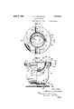
- Figure 1 is a top plan view of an ash receptacle constructed according to the present invention.
- Figure 2 is a side elevational view in partial section along the plane of the line 2-72 of Figure 1.
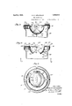
- Figure 3 is a fragmentary sectional view taken on the plane of the line 3 3 of Figure 1.
- Figure 4 is a view similar to Figure 3 with the closure in the open position.
- Figure 5 is a sectional View of a modified form taken on a plane corresponding to the plane of the line 5 5 of Figure 4.
- the present ash receptacle preferably includes a sheet metal receptacle 10 and a sheet metal cover or ash receiver 11.
- the receptacle 10 is preferably provided with a base 12 which may also be stamped from sheet metal and Which is provided with an outwardly flaring part 13 having a curled edge 14 for engagement With any convenient type of supporting surface.
- Vbase 12 is formed With a stamped cylindrical depression 15 capable of receiving a complef mentary stamped cylindrical projection 16 which is formed on the bottom of the base 10.
- the top of base 12 is formed With a flat annular portion 17 adapted to engage a similar annular portion 18 on the bottom of receptacle 1() and the receptacle 10 may be secured to base 12 by a single rivet 19, by spot Welding or other convenient securing means such as a bolt.
- the stamped formations 15 and 16 on the receptacle and base automatically locate the base 12 in proper position on the receptacle 10 so that the outer surface of the base 12 and that of receptacle 10 are in substantially perfect registry.
- the exact shape of the receptacle 10 may take a plurality of different forms depending upon the ornamental effect desired but in the present embodiment the upper part of the receptacle 10 is provided with a substantially cylindrical portion 20 capable of being received in a complementary cylindrical or annular flange 2l formed upon the cover 1l.
- the cylindrical ange 2O may be formed with a. stamped groove 22 formed in each side of the receptacle l() near the top, the groove e3:- tending inwardly from the top downwardly as at 23 and horizontally as at 24.
- the annular flange 21 carried by cover l1 may also be formed with al stamped inwardly extending protuberanceY 25 whichis adapted -to-bereceived in the groove 23 to secure the cover l1 on receptacle l0.
- the cover is secured upon the receptacle by insertingthe protuberance 25 in grooves 22 and turning the cover in clock-wise direction while pushing the cover on the receptacle.
- rlhe securing device for the cover upon the receptacle lO is thus made quickly detachableand it is capable of formation inthe cover and receptacle by stamping operations thereby eliminating the necessityy for other machining operations.
- t should be understood, however, that other forms of quickly detachable securing devices may also be employed.
- the cover l1 is also preferably formed with a ⁇ substantially'flat annular portion 26 for providing spacefor the securement of cigar holders 27 'and for the purpose of a hand rest in the use and operation of the ash receiver.
- the cigar holders 27 may consist of curved sheet Vmetalv members lsubstantially -a's shown, which are secured-totlieflat portion 26er' cover 11 by rivets 28, spot welding, brazing or other convenient'fastening means. Any numbero ⁇ f cigarhold'ers may be' employed.
- the vcover 1l also forms an ash receiverfor receiving ashes and holding them preliminary to their vdischarge into the receptacle l0, andfor'l this purpose the cover 26- is provided with'an inwardly extending-stamped depression 29 adapted' to receive refuseand 'direct lit into the receptacle 10.
- the receiver A29 - is preferably substantially semi-spherical in form thereby providing inwardly tapering sides30 which direct the' refuse toward a discharge opening 3l.
- the discharge ⁇ opening may take a number of differentk shapes such as, for instance, the oval type of opening shown in Figure l which gives a maximum discharge area or the circular 'discharge opening 32 shown in Figure 5 which gives va symmetrical appearance to the top of the ashV receiver.
- The'ash receiver V29 having a substantially spherical formation, the edges V33 of the discharge openings '31, 32l are disposedat equal distances from-'a' common center so thatA they are capable ofI lslidaloly engaging-any refuse which might remain upon the upper 'surface 34 fofa closure35'for vthe discharge openings 31,32.
- the Vclosure -35 lalsol consists' ofa Istamped sheetmetalmember of substantially spherical shape whichl has an in-nervsurface'36 complementary to the adjacent surface 37 on the cover l1 inside receptacle l0.
- the cover ll is also provided with a slot 38 located in the flat portion 26 adjacent the ash receiver 29 and the closure 35 is formed with an upwardly projecting operating member 39 which extends kthrough the slot 38.
- the actuating' member 39 is also formed with an offset 4l and the slot 38 is slightly spaced from theedge of the receiver '29, thereby providingspace fora spring 40.
- the closure 35 is movably mounted on cover ll by a pair of rivets 42, bolts or other pivotal mode of securement and the rivets 42 are located substantially upon the line of a diameter of the sphere of which the. parts 36, 37 may be considered surfaces.
- the closure 35 is thus pivotally mounted upon'a complementary spherical member so that the closure 35 slidablyl engages the adjacent surface 37 of the receiver 29.
- rlheedges 33surrounding discharge openings 31, 32 are adapted to sweep the relatively light-refuse off the closure 35 whenthe closure is movedfrom'the position of Figure 3 to the position of lF igure 4.
- the actuating member 39 is preferably provided with a laterally projecting flange 43, which maybe curved as shown iii- Figure 4 to provide an upper concave surface l'for convenient engagement with the hand orfingers of the operator.
- the edges ofthe actuating member 39 may be curved as at 45 and 46 so as tof provide ya continuous closureA of the slot ⁇ 38 during the movement of the lactuating member.
- the edge 46 is formed upon a radius with respect' to the centerv of rivet 41, which corresponds to the distance between the center of rivet 4l and the adj acent' end of slot 38.
- the edge 45 is formed upon afradiusiwith respect to the center of rivet' 41,1which vcorresponds to the distance between the center of rivet4l and the other end of slot 38.
- the actuating member/39 is also preferably formed with a stop 44 for definitely determining the final position of closure 35 and this stop may consist of a laterally projecting flange, the upper edge of which is adapted to engage below the flat portion 26 of the cover ll at one end of the slot 38.
- the stop 44 is located on the closure 35 in such position that it will engage the under side of the cover when the closure is in the closed' position as yshown in Figure 3.
- vThe vthu-mb piece or flange 43 is located on the actuating member 39 in such position that the thumb piece lis above the cover at the :opposite sidefiof 'the 13G' actuating member 39 from the stop 44.
- the actuating member-39 is thus provided with a maximum range of movement before the flange or thumb piece 43 strikes the upper part of cover ll.
- the closure 35 of the present ash receiver may be made weight actuated or spring actuated but is preferably provided with a spring 47 adapted to urge the closure 35 to closed position. rIhe spring 47 may have one end 48 hooked about the curved surface 46 and engaging the edge 49 of closure 35.
- the spring is preferably wrapped about the rivet 4l between the actuating member 39 and the curved portion 30 of the ash receiver 29 and the opposite end 50v of spring 47 is extended beneath theflat portion 26 of cover 11 and placed under tension to maintain the closure 35 in the position of Figure 3.
- the spreading of the portions 48 and 50 of spring 47 urges the closure 35 into closed position and maintains stop. 44 in engagement with the under side of cover ll.
- the relative sizes of the discharge opening 3l and the remaining curved portions 30 of the ash receiver 29 are preferably such that the closure 35 may completely open the discharge opening 3l, so that the edges 33 of the discharge opening 3l may effect the function of cleaning the sliding closure 35 during the opening operation.
- the closure 35 is, of course of suilicient width to cover the discharge opening 3l and overlap the edges 33 of the receiver 29 and the closure itself is preferably oblong in shape taking substantially the same form as a segment of the spherical surface.
- The. modification illustrated in Figure is substantially the same as that described except the discharge opening 32 is made circular'.
- the closure 35 is also preferably provided with a distributing member 51 which also increases the weight of the closure 35 and aids in its return to closed position by gravity.
- the distributing member 51 may consist of a fiat sheet metal member of the shape illustrated or any equivalent shape carried by the under side of closure 35 and adapted to engage the top of a pile of refuse below the discharge opening 31 to sweep the tcp of the pile toward the side in the receptacle l0 and continuously level ofi' the refuse within the receptacle l0.
- the distributing member 5l may be secured to the lower side of closure 35 by providing a flange 52 at right angles to the body of distributing member 5l and curved complementarily to the bottom of closure 35.
- the flange 52 may be secured to closure 35 by spot welding, brazing, riveting or other convenient fastening means.
- the operation of the present ash receptacle is as follows: Ashes may be discharged into the receiver 29 and immediately passed on into the receptaclelO by simultaneously dropping the ashes and actuating the closure 35 to open position by pushing on the thumb or finger piece 43, in which case the sides of the spherical ash receiver 29 will direct the ashes or other refuse through the discharge opening 31. 4
- the ashes need not be discharged from the ash receiver 29 into the receptacle 10 except at periodic intervals by the movement of the closure from the position of Figure 3 to the position of Figure 4.
- the ashes or other refuse lying upon the closure 35 will be swept olf the closure by the edge 33 of the ash receiver 29 and the ash receiver may thus be maintained in substantially sanitary condition at all times.
- the closure 35 may b-e conveniently moved to open position by resting a part of the hand upon the flat part 26 of cover 11 and applying the thumb or finger to the thumb piece 43, pushing the actuating member 39 -to the left in Figure 3.
- the closure 35 will then be pivoted upon the rivets 4l and will slidably engage the complementary spherical surface 37, moving to th-e position of Figure 4 against the tension of spring 47.
- rl ⁇ he ashes or other refuse which accumulates in the receptacle l() will ordinarily form a pile immediately below the discharge opening 3l, but as soon as the ashes reach a sufficient height the top of the pile will be continuously levelled and distributed in the container l0 by the operation of the distributing member 5l which sweeps over the refuse in the receptacle l0 and enables utilization of a greater part of the volume of receptacle 10.
- an improved ash receptacle of the type which is provided with an ash receiver for the preliminary reception of ashes ⁇ and other refuse which may be discharged into the receptacle at will.
- the present receptacle may be very economically manufactured by stamping its parts from sheet metal and the present receptacle is peculiarly adapted to be maintained in a clean and sanitary condition, e'ecting a complete discharge of refuse from the ash receiver into the receptacle by the ordinary operation of its mechanism.
- a refuse receptacle comprising. a ylower container,..a refuse. receiving cover .carried by said container, Asaid Y.cover .having .anfin- Wardlyvextending spherical .formation with adischarge ape-rturepa closureof substantially v ⁇ spherical formation movably mounted on said ⁇ cover .to control .saididischargeiapen ture; a-spring urging said vclosure to closed positionuand a. refuse distributingi member carriedby fsaid ⁇ closure .ivithin said container.
- lA refuseV receiver comprisingr a container, ametal cover member therefor, said cover member having'a substantially flat upper border flange and. havinga. h'emispherical formation surrounded by said. border flange, said hemispherical lformation having an aperturey in thev same, a .closurememberrof spherical shape and ofsullicient .area to cover Said opening, said closure member being formed on a larger radius, means for pivotally mounting said-.closure member. at both sidesY of .saidhemispherical formation, said closure member .having anA integral flange extending upwardithrough a slotin said borderflange, al laterally.
- a refuse receiver comprising a container, a metal cover'member therefor, said cover member having a substantial-ly flat-upper border flange and having a hemispherical formation surrounded by'said borderflange, said hemispherical formation having. an aperture in the same, a closure member of spherical shapeand of sufficient area to.
- 'A refuse receiver comprising a container, a metal cover member therefor, said cover member having a substantially llat upper border flange Vand having a hemispherical formation surrounded by saidborderflange, said hemispherical Vformation having an aperture inthe same, a closure member of spherical shape and of suliicient area tocover said opening, said closure member being formed on a Ylarger radius, means for pivotally mounting said closure member at both sides of said hemispherical formation, said closure member having. an. integral'flange extending upward through a slot in said bordel' flange, a laterally.
Landscapes
- Closures For Containers (AREA)
Description
April 5, 1932. A. c. GRUNWALD 1,852,610
\ ASH RECEPTACLE Filed March 17. 1930 2 Sheets-Sheet l prLS, 1932. A, Q GRUNWALD 1,852,610
AISH RECEPTACLE Filed March 17, 1950 2 Sheets-Sheet 2 Patented pr. 5, 1932 UNITED `s TES ALBERT C. GRUNWALD, OF RIVER FOREST, ILLINOIS, ASSIGNOR TO PRECISION METAL WORKERS, OF CHICAGO, ILLINOIS, .A CORPORATION OF ILLINOIS ASH RECEIPTACLE Application led March 17, 1930. Serial No. 436,425.
The present invention relates to receptacles, and is particularly concerned With receptacles adapted to receive ashes, cigars, cigarettes and other forms of light refuse.
One'of the objects of the invention is the provision of an improved ash receptacle, adapted to be used in homes or public places, for receiving ashes and other forms of refuse While still maintaining a sanitary and neat appearance.
Another object is the provision of an improved ash receiver which maybe maintained in clean condition by constantly discharging the refuse into a larger receptacle or which may be used in the usual manner and discharged at intervals Whenever it is desired to empty the receiver.
Another object is the provision of an improved ash receiver which is peculiarly adapted to be actuated conveniently by the hand of the user While still holding a cigar or cigarette in the hand. i
Vinc-ther object is the provision of an ash receptacle of the type having an auxiliary ash 'I receiver or tray, Which is provided with a discharge opening and a closure that is substantially self-cleaning to maintain the closure clear of light refuse, ashes, etc. and assure a complete discharge- Another object is the provision of a cigar holder and ash receptacle which shall be neat in appearance, sanitary in its operation, having a simple yet durable construction, With parts which lend themselves readily to manufacture by-diesfrom ordinary sheet metal.
Other objects and advantages of the invention will be apparent from the following description and from the accompanying draivings, in Which similar characters of reference indicate similar parts throughout the several views.
Referring to the drawings, of which there are two sheets, Figure 1 is a top plan view of an ash receptacle constructed according to the present invention.
Figure 2 is a side elevational view in partial section along the plane of the line 2-72 of Figure 1.
Figure 3 is a fragmentary sectional view taken on the plane of the line 3 3 of Figure 1.
Figure 4 is a view similar toFigure 3 with the closure in the open position.
Figure 5 is a sectional View of a modified form taken on a plane corresponding to the plane of the line 5 5 of Figure 4.
Referring to Figures 1 and 2, the present ash receptacle preferably includes a sheet metal receptacle 10 and a sheet metal cover or ash receiver 11. The receptacle 10 is preferably provided with a base 12 which may also be stamped from sheet metal and Which is provided with an outwardly flaring part 13 having a curled edge 14 for engagement With any convenient type of supporting surface.
In order to secure the base 12 to the receptacle 10 in a very economical manner, the
Vbase 12 is formed With a stamped cylindrical depression 15 capable of receiving a complef mentary stamped cylindrical projection 16 which is formed on the bottom of the base 10. The top of base 12 is formed With a flat annular portion 17 adapted to engage a similar annular portion 18 on the bottom of receptacle 1() and the receptacle 10 may be secured to base 12 by a single rivet 19, by spot Welding or other convenient securing means such as a bolt. The stamped formations 15 and 16 on the receptacle and base automatically locate the base 12 in proper position on the receptacle 10 so that the outer surface of the base 12 and that of receptacle 10 are in substantially perfect registry. The two parts may then be secured together quickly by the use of ordinary machinery with a very low percentage of defective devices, such as might be the case Where these parts must be held together and adjusted to their proper relative position by means of the eye of the operator. It should be understoodv that any forms of complementary formations 15 and 16 may be employed but those illustrated are preferred on account of the simplicity and effectiveness of this arrangement.
The exact shape of the receptacle 10 may take a plurality of different forms depending upon the ornamental effect desired but in the present embodiment the upper part of the receptacle 10 is provided with a substantially cylindrical portion 20 capable of being received in a complementary cylindrical or annular flange 2l formed upon the cover 1l. The cylindrical ange 2O may be formed with a. stamped groove 22 formed in each side of the receptacle l() near the top, the groove e3:- tending inwardly from the top downwardly as at 23 and horizontally as at 24. The annular flange 21 carried by cover l1 may also be formed with al stamped inwardly extending protuberanceY 25 whichis adapted -to-bereceived in the groove 23 to secure the cover l1 on receptacle l0. The cover is secured upon the receptacle by insertingthe protuberance 25 in grooves 22 and turning the cover in clock-wise direction while pushing the cover on the receptacle. rlhe securing device for the cover upon the receptacle lO is thus made quickly detachableand it is capable of formation inthe cover and receptacle by stamping operations thereby eliminating the necessityy for other machining operations. t should be understood, however, that other forms of quickly detachable securing devices may also be employed.
vThe cover l1 is also preferably formed with a `substantially'flat annular portion 26 for providing spacefor the securement of cigar holders 27 'and for the purpose of a hand rest in the use and operation of the ash receiver.
The cigar holders 27 may consist of curved sheet Vmetalv members lsubstantially -a's shown, which are secured-totlieflat portion 26er' cover 11 by rivets 28, spot welding, brazing or other convenient'fastening means. Any numbero`f cigarhold'ers may be' employed.
The vcover 1l also forms an ash receiverfor receiving ashes and holding them preliminary to their vdischarge into the receptacle l0, andfor'l this purpose the cover 26- is provided with'an inwardly extending-stamped depression 29 adapted' to receive refuseand 'direct lit into the receptacle 10. The receiver A29 -is preferably substantially semi-spherical in form thereby providing inwardly tapering sides30 which direct the' refuse toward a discharge opening 3l. The discharge `opening may take a number of differentk shapes such as, for instance, the oval type of opening shown in Figure l which gives a maximum discharge area or the circular 'discharge opening 32 shown inFigure 5 which gives va symmetrical appearance to the top of the ashV receiver.
The'ash receiver V29 having a substantially spherical formation, the edges V33 of the discharge openings '31, 32l are disposedat equal distances from-'a' common center so thatA they are capable ofI lslidaloly engaging-any refuse which might remain upon the upper 'surface 34 fofa closure35'for vthe discharge openings 31,32.
The Vclosure -35 lalsol consists' ofa Istamped sheetmetalmember of substantially spherical shape whichl has an in-nervsurface'36 complementary to the adjacent surface 37 on the cover l1 inside receptacle l0.
The cover ll is also provided with a slot 38 located in the flat portion 26 adjacent the ash receiver 29 and the closure 35 is formed with an upwardly projecting operating member 39 which extends kthrough the slot 38. The actuating' member 39 is also formed with an offset 4l and the slot 38 is slightly spaced from theedge of the receiver '29, thereby providingspace fora spring 40.
The closure 35 is movably mounted on cover ll by a pair of rivets 42, bolts or other pivotal mode of securement and the rivets 42 are located substantially upon the line of a diameter of the sphere of which the. parts 36, 37 may be considered surfaces. The closure 35 is thus pivotally mounted upon'a complementary spherical member so that the closure 35 slidablyl engages the adjacent surface 37 of the receiver 29. rlheedges 33surrounding discharge openings 31, 32 are adapted to sweep the relatively light-refuse off the closure 35 whenthe closure is movedfrom'the position of Figure 3 to the position of lF igure 4.
The actuating member 39 is preferably provided with a laterally projecting flange 43, which maybe curved as shown iii-Figure 4 to provide an upper concave surface l'for convenient engagement with the hand orfingers of the operator.
The edges ofthe actuating member 39 may be curved as at 45 and 46 so as tof provide ya continuous closureA of the slot `38 during the movement of the lactuating member. Thus the edge 46 is formed upon a radius with respect' to the centerv of rivet 41, which corresponds to the distance between the center of rivet 4l and the adj acent' end of slot 38. The edge 45 is formed upon afradiusiwith respect to the center of rivet' 41,1which vcorresponds to the distance between the center of rivet4l and the other end of slot 38. When the 'closure 35 is rotated upon' the rivet 4l it will be evident that the curved surfaces 45 and 46 are maintained in the'same relative. position with respect to the ends of slot38 and the curved edges 45 and 46 of actuating member 39 slidably enga-ge the ends of slot 38 to maintain the slot in closed position.
The actuating member/39 is also preferably formed with a stop 44 for definitely determining the final position of closure 35 and this stop may consist of a laterally projecting flange, the upper edge of which is adapted to engage below the flat portion 26 of the cover ll at one end of the slot 38. The stop 44 is located on the closure 35 in such position that it will engage the under side of the cover when the closure is in the closed' position as yshown in Figure 3. vThe vthu-mb piece or flange 43 is located on the actuating member 39 in such position that the thumb piece lis above the cover at the :opposite sidefiof 'the 13G' actuating member 39 from the stop 44. The actuating member-39 is thus provided with a maximum range of movement before the flange or thumb piece 43 strikes the upper part of cover ll.
The closure 35 of the present ash receiver may be made weight actuated or spring actuated but is preferably provided with a spring 47 adapted to urge the closure 35 to closed position. rIhe spring 47 may have one end 48 hooked about the curved surface 46 and engaging the edge 49 of closure 35.
The spring is preferably wrapped about the rivet 4l between the actuating member 39 and the curved portion 30 of the ash receiver 29 and the opposite end 50v of spring 47 is extended beneath theflat portion 26 of cover 11 and placed under tension to maintain the closure 35 in the position of Figure 3. The spreading of the portions 48 and 50 of spring 47 urges the closure 35 into closed position and maintains stop. 44 in engagement with the under side of cover ll.
The relative sizes of the discharge opening 3l and the remaining curved portions 30 of the ash receiver 29 are preferably such that the closure 35 may completely open the discharge opening 3l, so that the edges 33 of the discharge opening 3l may effect the function of cleaning the sliding closure 35 during the opening operation.
The closure 35 is, of course of suilicient width to cover the discharge opening 3l and overlap the edges 33 of the receiver 29 and the closure itself is preferably oblong in shape taking substantially the same form as a segment of the spherical surface. The. modification illustrated in Figure is substantially the same as that described except the discharge opening 32 is made circular'.
The closure 35 is also preferably provided with a distributing member 51 which also increases the weight of the closure 35 and aids in its return to closed position by gravity. The distributing member 51 may consist of a fiat sheet metal member of the shape illustrated or any equivalent shape carried by the under side of closure 35 and adapted to engage the top of a pile of refuse below the discharge opening 31 to sweep the tcp of the pile toward the side in the receptacle l0 and continuously level ofi' the refuse within the receptacle l0. The distributing member 5l may be secured to the lower side of closure 35 by providing a flange 52 at right angles to the body of distributing member 5l and curved complementarily to the bottom of closure 35. The flange 52 may be secured to closure 35 by spot welding, brazing, riveting or other convenient fastening means.
It should also be noted that every one of the improved features described herein need not be employed in every embodiment of the invention, but the invention includes such modified forms having only those novel features which accomplish the purposes desired of much more simple devices.
The operation of the present ash receptacle is as follows: Ashes may be discharged into the receiver 29 and immediately passed on into the receptaclelO by simultaneously dropping the ashes and actuating the closure 35 to open position by pushing on the thumb or finger piece 43, in which case the sides of the spherical ash receiver 29 will direct the ashes or other refuse through the discharge opening 31. 4
If desired the ashes need not be discharged from the ash receiver 29 into the receptacle 10 except at periodic intervals by the movement of the closure from the position of Figure 3 to the position of Figure 4. The ashes or other refuse lying upon the closure 35 will be swept olf the closure by the edge 33 of the ash receiver 29 and the ash receiver may thus be maintained in substantially sanitary condition at all times.
The closure 35 may b-e conveniently moved to open position by resting a part of the hand upon the flat part 26 of cover 11 and applying the thumb or finger to the thumb piece 43, pushing the actuating member 39 -to the left in Figure 3. The closure 35 will then be pivoted upon the rivets 4l and will slidably engage the complementary spherical surface 37, moving to th-e position of Figure 4 against the tension of spring 47.
When the actuating member 39 is released, the closure 35 moves back to the position of Figure 3 by gravity and by virtue of the tension of spring 47 It should be noted that the surface of the closure 35 need not necessarily engage the surface 37 of receiver 29 provided these two sheet metal members are sufliciently close to each other so that refuse is swept olf the closure 35 by edge 33. rl`he ashes or other refuse which accumulates in the receptacle l() will ordinarily form a pile immediately below the discharge opening 3l, but as soon as the ashes reach a sufficient height the top of the pile will be continuously levelled and distributed in the container l0 by the operation of the distributing member 5l which sweeps over the refuse in the receptacle l0 and enables utilization of a greater part of the volume of receptacle 10.
It will thus be observed that I have invented an improved ash receptacle of the type which is provided with an ash receiver for the preliminary reception of ashes` and other refuse which may be discharged into the receptacle at will. The present receptacle may be very economically manufactured by stamping its parts from sheet metal and the present receptacle is peculiarly adapted to be maintained in a clean and sanitary condition, e'ecting a complete discharge of refuse from the ash receiver into the receptacle by the ordinary operation of its mechanism.
ist
.Whileethe embodiment. l.which .has been selected to illustratetithe.invention, consists of an Jash receptacle it should be Aunderstood that'thepresent-.deviceis not .limited in size or use to ashreoep-tion.butzmayibe employed for receiving. materials of anylrindv byprovidinga receptacle 0fappropriatevsize.
.While I have illustrated -and .described a specilic form/of. oneembodiment of. my invention, th-is is capabler ofmanymodifloations Withoutfdepartingfrom the spirit of theinvention and I do not Wish to be limited to the v,precise `details of the construction set forth but desirey tofavail. myself of.all.advantages within. the scope ofthe. appended claims. n
. Having thus'described-my invention, what I claim asinetv and. desire .to secure by Letters Patent ofthe UnitedStates is:
. l. .A refuse receptacle comprising. a ylower container,..a refuse. receiving cover .carried by said container, Asaid Y.cover .having .anfin- Wardlyvextending spherical .formation with adischarge ape-rturepa closureof substantially v`spherical formation movably mounted on said `cover .to control .saididischargeiapen ture; a-spring urging said vclosure to closed positionuand a. refuse distributingi member carriedby fsaid `closure .ivithin said container.
vv2..,A refuse .receiver rcomprising .a container," a` metal cover member. therefor, said cover member having a substantially flat upper border flangeand .havinga hemispherical formation surrounded. by said border flange, saidhemispherical formation having an aperture in the same,.a closure member of spherical shape and of sufficient area-to cover said opening, said closure member being formedona la-rger radius, means'for pivotally mounting said closure member at both-sides of said hemispherical formation, said closure member having an integral flange extending upward through a slot in said border flange, -an'd a laterally. projecting thumb engaging flange .above said border flange.
. .3. lA refuseV receiver comprisingr a container, ametal cover member therefor, said cover member having'a substantially flat upper border flange and. havinga. h'emispherical formation surrounded by said. border flange, said hemispherical lformation having an aperturey in thev same, a .closurememberrof spherical shape and ofsullicient .area to cover Said opening, said closure member being formed on a larger radius, means for pivotally mounting said-.closure member. at both sidesY of .saidhemispherical formation, said closure member .having anA integral flange extending upwardithrough a slotin said borderflange, al laterally. projecting lthumb en gaginglflange abovefsaid border flange, and a springarrangedmabout -one .of thepivots of said closure having one end: engaging beneath said cover and .having the other end hooked about said closure to urge said closure to closedy position.
4. A refuse receiver comprising a container, a metal cover'member therefor, said cover member having a substantial-ly flat-upper border flange and having a hemispherical formation surrounded by'said borderflange, said hemispherical formation having. an aperture in the same, a closure member of spherical shapeand of sufficient area to. cover vsaid opening, said closure member being vformed on a larger radius, means for pivotally mounting said closuremember at both sides of said hemispherical formation, said closure member having an integral 'flange extending upward through a slot in saidborder flange, a laterally 'projecting` thumb engaging `llange above said border flange,a spring arranged about one of the pivots of said closure having one end' enga-ging beneath said cover and having the other end hooked about said closure to :urge said closure to closed position, and a refuse spreader comprisinga downwardly extending flange carried by said closure and adapted to sweepv across a pile of refuse When said closure'is opened and tobe swept across the dischargedrefuse .by said spring upon release of said closure to distribute the refuse.
5. 'A refuse receiver comprising a container, a metal cover member therefor, said cover member having a substantially llat upper border flange Vand having a hemispherical formation surrounded by saidborderflange, said hemispherical Vformation having an aperture inthe same, a closure member of spherical shape and of suliicient area tocover said opening, said closure member being formed on a Ylarger radius, means for pivotally mounting said closure member at both sides of said hemispherical formation, said closure member having. an. integral'flange extending upward through a slot in said bordel' flange, a laterally. projecting thumb engaging flange above saidborder'flange, a spring arranged about one ofthe pivots of said closure having one end= engaging beneath said cover and having the other end hooked about said .closure to urge said closure to closed position, and a plurality .of curved cigar holding members secured tothe upper surface of Asaid border flange.
In Witness Whereof,I hereunto subscribe my name this lfZthday of March, 1930.
AKLBERT- C. GRUNVVALD.
Priority Applications (1)
| Application Number | Priority Date | Filing Date | Title |
|---|---|---|---|
| US436425A US1852610A (en) | 1930-03-17 | 1930-03-17 | Ash receptacle |
Applications Claiming Priority (1)
| Application Number | Priority Date | Filing Date | Title |
|---|---|---|---|
| US436425A US1852610A (en) | 1930-03-17 | 1930-03-17 | Ash receptacle |
Publications (1)
| Publication Number | Publication Date |
|---|---|
| US1852610A true US1852610A (en) | 1932-04-05 |
Family
ID=23732346
Family Applications (1)
| Application Number | Title | Priority Date | Filing Date |
|---|---|---|---|
| US436425A Expired - Lifetime US1852610A (en) | 1930-03-17 | 1930-03-17 | Ash receptacle |
Country Status (1)
| Country | Link |
|---|---|
| US (1) | US1852610A (en) |
Cited By (1)
| Publication number | Priority date | Publication date | Assignee | Title |
|---|---|---|---|---|
| US3233773A (en) * | 1962-12-04 | 1966-02-08 | Purex Corp Ltd | Baffle system for agitated cleaning tanks |
-
1930
- 1930-03-17 US US436425A patent/US1852610A/en not_active Expired - Lifetime
Cited By (1)
| Publication number | Priority date | Publication date | Assignee | Title |
|---|---|---|---|---|
| US3233773A (en) * | 1962-12-04 | 1966-02-08 | Purex Corp Ltd | Baffle system for agitated cleaning tanks |
Similar Documents
| Publication | Publication Date | Title |
|---|---|---|
| US2765194A (en) | Container for solid or liquid insecticide, deodorant, or the like | |
| US1852610A (en) | Ash receptacle | |
| US2059105A (en) | Ashtray | |
| US2207040A (en) | Ash tray and cigarette extinguisher | |
| US2111480A (en) | Ash receiver | |
| US1696483A (en) | Metal box | |
| US1718400A (en) | Pocket ash container | |
| US2182623A (en) | Condiment holder | |
| US3877600A (en) | Closure assembly | |
| US1848388A (en) | Extinguisher for cigarettes or the like | |
| US2004537A (en) | Smoker's accessory | |
| US1583738A (en) | Smoker's article | |
| US1799897A (en) | Ash tray | |
| US1865902A (en) | Ash receptacle | |
| US2504597A (en) | Compact smoker | |
| US1800665A (en) | Ash receptacle | |
| US1779327A (en) | Ash tray | |
| US2449965A (en) | Ash receptacle for armrests of vehicle seats | |
| US2588537A (en) | Smoker's appliance | |
| US2029342A (en) | Smoking stand | |
| US2067406A (en) | Ash receiver | |
| US2026169A (en) | Ash holder | |
| US1993493A (en) | Powder dispensing top | |
| US1910988A (en) | Ash receptacle | |
| US2038370A (en) | Combination ashtray and pipe cleaner |