US1852591A - Rock drill - Google Patents
Rock drill Download PDFInfo
- Publication number
- US1852591A US1852591A US299493A US29949328A US1852591A US 1852591 A US1852591 A US 1852591A US 299493 A US299493 A US 299493A US 29949328 A US29949328 A US 29949328A US 1852591 A US1852591 A US 1852591A
- Authority
- US
- United States
- Prior art keywords
- valve
- piston
- chamber
- valves
- cylinder
- Prior art date
- Legal status (The legal status is an assumption and is not a legal conclusion. Google has not performed a legal analysis and makes no representation as to the accuracy of the status listed.)
- Expired - Lifetime
Links
- 239000011435 rock Substances 0.000 title description 15
- 239000012530 fluid Substances 0.000 description 38
- 230000004048 modification Effects 0.000 description 9
- 238000012986 modification Methods 0.000 description 9
- 238000010276 construction Methods 0.000 description 5
- 238000013459 approach Methods 0.000 description 2
- 230000006835 compression Effects 0.000 description 2
- 238000007906 compression Methods 0.000 description 2
- 230000007246 mechanism Effects 0.000 description 2
- 208000025940 Back injury Diseases 0.000 description 1
- 230000000694 effects Effects 0.000 description 1
- 238000004519 manufacturing process Methods 0.000 description 1
- 230000008092 positive effect Effects 0.000 description 1
- 230000009467 reduction Effects 0.000 description 1
Images
Classifications
-
- B—PERFORMING OPERATIONS; TRANSPORTING
- B25—HAND TOOLS; PORTABLE POWER-DRIVEN TOOLS; MANIPULATORS
- B25D—PERCUSSIVE TOOLS
- B25D9/00—Portable percussive tools with fluid-pressure drive, i.e. driven directly by fluids, e.g. having several percussive tool bits operated simultaneously
- B25D9/14—Control devices for the reciprocating piston
- B25D9/16—Valve arrangements therefor
Definitions
- rllhis invention relates to rock drills, but chamber B is provided with a closure in the more particularly to valve mechanism for efform of a front cylinder washer D having a fecting the distribution of pressureiiuid to bore E for guiding a stem or extension F Vof the cylinder of rock drills of the hammer the piston C.
- a free exhaustn port G in the type, i l cylinder is controlled by the piston C.
- the objects of the invention are to simplify f
- a suitable closure is provided for the rearthe construction of rock ydrills of this type, ward end of the piston chamber B inthe to insure an abundant admission of pressure form of a plate H.
- the plate H is disposed liuid to the cylinder with a minimum lift of Vinan enlarged bore J in the rearward end of wthe valve or valves, to lessen the chances of the cylinder A and forms a seat for a back injury to the valves, to render the valve mechhead K which may be secured to the cylinder 'anism inexpensive to manufacture Vand main* by any suitable means, such as side bolts (not tain, and to obtain a rapid and positive action shown).
- the back head K serves as a of the percussive element of the rock drill.
- housingfor the head L of a rifle bar O which Other objects will be in part obvious and extends through the plate H and slidably enpart pointed out hereinafter. gages the piston C in a well known manner.
- FIG. 1 is a sectional elevation of a porlixedly in a recess S in the back head K in tion of a rock drill showing one form which which the head L also lies.
- valve chest designated generally by VT is dis- Figure 4 is an enlarged transverse view posed in the bore J to seat on an end wall U taken through Figure 2 on the line 4--4 lookin the cylinder A and in turn forms a seat for ing in the direction indicated by the arrows, the plate H.
- the valve chest T comprises a Figure is alongitudinal sectional elevarearward end plate V, a forward end plate tion of a rock drill showing a modified form W and an intermediate plate X.
- the plates of the invention may be Figure 6 on the line 5-5 looking in the disecurely clamped in the operative position rection indicated by the arrows, by means of the side bolts which exert a pres- Figure 6 is atransverse view taken through sure on the back head.
- Any other suitable Figure 5 on the line 6 6 looking in the direcmeans may, however, be vprovided for maintion indicated by the arrows, and showing the ltaining these parts in the operative position.
- the plate X may be a fiat plate of uniform
- Figure 7 is a perspective view of a valve, thickness throughout and is provided with and a plurality of valve chambers Y in which are Figure 8 is a similar view of a valve guide.
- disposed valves Z in the form of thin flat it Referring to the drawings and at first more disks or plates guided only on their periphparticularly to Figure l, A designates a cylinder having a piston chamber B in which is disposed a reciprocatory hammer piston C for delivering blows to a working implement (not shown). The front end of the piston eries by the chambers Y. At the rearward sides of the valve chambers Y and on the plate V are valve seats b which act as stops for the valves Z.
- valve seats b are preferably of considerably smaller diameter than the valves Z so that an annular area of the rearward ends of the valves Z will be at all times exposed to pressure fluid.
- the plate W is provided with valve seats o for the front ends of the valves Z7 said valve seats 0 being of the same proportions and conformation as the valve seats b so that a similar annular area on the front surfaces of the valves Z will also be constantly subjected to live pressure iiuid.
- valve seats b and c By thus forming the Valve seats b and c, shoulders cl and e will be formed around the valve seats b and o and said shoulders are only slightly spaced from the plate X to assure the restriction of the pressure fluid entering the valve chambers Y.
- inlet passages f lead from the rearward ends of the valve chambers Y through the plate V to the rearward end o-f the piston chamber B.
- Front inlet passages g lead from the valve seats c through the plate W and through the cylinder A to the front -end of the piston chamber B for conveying pressure fluid thereto to impel the piston C in a rearwardly direction.
- the pressure fluid utilized for actuating the piston C may be introduced into the drill yat a point adjacent a throttle valve 71. disposed in lthis instance in a valve chamber j in the back head K.
- the throttle valve h is provided with a central chamber la and has a port 0 to afford communication between the chamber 7c and a passage p leading from the throttle valve chamber to a supply reservoir g, located in this instance in the back head K.
- Pressure introduced into the supply reservoir g is rconveyed through the valve chest by supply passages r which communicate at their other ends with a supply chamber 8 surrounding in this instance the valve chambers Y.
- the supply chamber is of annular shape and is of a depth to lie both below and above the plate X and of a width to communicate-with each vave chamber Y at opposite sides thereof so that in effect it forms a portion of each valve chamber. This assures an abundant supply of pressure fluid to each inlet passage immediately after the valves shift.
- the supply passages r however, extend to the lowermost point of the supply chamber sothat both sides of the valves Z will be constantly exposed to pressure fluid ⁇ in a manner to be more fully described hereinafter.
- the plates X, V and ⁇ W comprising the valve chest are provided with bores t of the same diameter as the piston chamber B for which the bores t form a continuation so that the piston C may reciprocate through the valve chest.
- valves Z During the passage of pressure fluid into the rearward end of the piston chamber B the entire rearward surfaces of the valves Z are exposed to pressure fluid so that the valves Z will remain firmly seated on the valve seats c. The valves Z will remain in this position until the piston C approaches the forward end of the piston chamber B.
- valves Z thus reversed pressure fluid will flow into the valve chambers Y through the restricted spaces between the shoulders e and the forward surface of the 'plate X into the valve chambers Y, thence through the linlet passages g into the front end of the piston chamber B to impel the piston C rearwardly.
- the cylinder A is provided at its rearward end with a bore u of sufficient depth to receive the valve chest o and a rotation ratchet 'w disposed in this instance on the valve chest o.
- the rotation ratchet w forms aseat for a back head which may be secured to the cylinder A in any well known manner.
- the valve chest o comprises forward and rearward end plates g/ and .e respectively and an intermediate plate 2. Seated on the rearward .surface of the plate z is a plate 3 to form a seat for the rotation ratchet w and for the head L of the riiie bar O.
- the back head at is also provided with a supply reservoir 4 which is in constant communication with the supply chamber s through supply passages rleading through the rotation ratchet w and the plates 3, z, 2 and y.
- the plate y forms a closure for the rearward end of the piston chamber B and pressure fluid is admitted to the front end of the piston chamber through an inlet passage 6 in the cylinder A communicating at its rearward end with a chamber 7 preferably formed in the plates 3 and a. From the chamber 7 to the ends of the valve chambers Y lead passages 8 for conveying pressure fluid from the rearward ends of the valve chambers Y to the chamber 7. The admission of pressure fluid to the rearward ends of the piston chamber B is effected through Vinlet passages 9 formed in the plate g/ and opening directly into the piston chamber B.
- the plates comprising the valve chamber o such as the plates y, e, 2 and 3 are each provided with bores 10 to receive the rifle bar O and form a guide therefor.
- rIhe construction of the plates comprising the valve chambers and the valve seats in this modification is the same as that described in connection with the previous modification.
- the operation is also practically the same and differs principally in that the chamber 7 may act as an expansion chamber so that as the piston C approaches the front end of the piston chamber an ample chamber is provided for the air compressed in the front end of the piston chamber and the piston C may therefore deliver a heavy blow against the working implement before sufficient pressure fluid is admitted to the front end of the piston chamber to retard the forward movement of the piston.
- the plate 12 is in turn seated on a plate 13 in the bore 11.
- the plate 13 forms a por-
- the plates 13 and 14 are provided in their adjacent surfaces with annular supply chambers 15 which communicate with the supply reservoir 4 through supply passages 16 in the rotation ratchet lw and the plates 12 and 13.
- the supply chambers 15 are formed in both the plates 13 and 14 so that the opposite sides of the valves Z andthe valve chambers Y may be constantly exposed to pressure fluid.
- valve guides 17 On the inner surface of the annular supply passages 15 are disposed valve guides 17 to receive the valves Z.
- the valve guides 17 are rows of small ports 18, the ports 18 being located valve seat b and the ports 19 adjacent the valve seats c.
- These ports 18 and 19 are of such cross sectional area that the pressure iuid is somewhat restricted during its passage from the valve chamber Y j
- the valve guides 17 are of a height equal to the depth of the supply chambers 15 so that when the parts are assembled in the drill the valve gui-des 17 will be heldagainst endwise movement.
- the pressure fluid is in this instance conveyed to the rearward end of the piston chamber B by inlet passages 2O formed in the plate 14 adjacent the supply chambers 15 into the and opening at their inlet ends into the valve seats 0.
- the admission of pressure fluid to the front end of the piston chamber B is effected through an inlet passage 21 formed inthe cylinder A and communicating at its rearward yend with a chamber 22 formed in the adjacent surfaces of the plates 12 and 13. From the chamber 22 lead passages 23 for conveying pressure fluid from the rearward ends of the valve chambers Y tothe chamber 22.
- this modification is substantially like that previously described and this modification differs from the prior described modifications ner in which the valves Z are guided.
- a fluid actuated rock drill the combination of a cylinder and a piston in the cylinder, an exhaust port for the cylinder, a valve chesthaving a plurality of and a supply passage, distributing valves in the valve chambers, a bore in the valve chest to slidably receive the piston, inlet passages leading from the valve chamber to the cylprincipally in the manvalve chambers inder, and a valve in the valve chamber controlling communication between the supply and inlet passages.
- a uid actuated rock drill the combination of a cylinder and a piston in the cylinder, an exhaust port for the cylinder, a valve chest in the cylinder having a plurality of valve chambers and a supply passage, distributing valves in the valve chambers, a bore in the valve chest to slidably receive the piston, inlet passages leading from the valve chamber to the cylinder, and a valve in the valve chamber controlling communication between the supply and inlet passages.
- a fluid actuated rock drill the combination of a cylinder and a piston, an exhaust port for the cylinder, a rifle' bar for rotating the piston, a valve chest encircling the rifle bar and having a plurality of valve chambers, a supply passage allording communication between the valve chambers and a source of pressure fluid supply, inlet passages leading from the valve chambers to the cylinder, and valves in the valve chambers controlling communication between the supply and inlet passages.
- a fluid actuated. roclr drill the combination of a cylinder and a piston, an exhaust port for the cylinder, a rifle bar for rotating -he piston and having a head, a valve chest encircling the rifle bar and forming a seat for the head, a plurality of valve chambers in the valve chest, a supply passage constantly conveying pressure fluid from a source of supply to the valve chambers, inlet passages leading from the valve chambers to the cylinder, and valves in the valve chambers for controlling the flow of pressure fluid from the supply passage to the inlet passages.
- a fluid actuated rock drill the combination of a cylinder having a piston chamber and a piston in the piston chamber, a'rifle bar for rotating the piston, a valve chest in the cylinder encircling the rifle bar and having a bore forming a continuation of the piston chamber, a plurality of valve chambers in the valve chest, a supply passage for conveying pressure fluid from a source of supply to the valve chambers, inlet passages leading from the valve chambers to the piston chamber, and valves in the valve chambers controlling the flow of pressure fluid from the supply passage to the inlet passages.
- a cylinder' having a piston chamber and a piston in the piston chamber
- a rifle bar for rotating the piston
- a head on the rifle bar a valve chest in the cylinder forwardly of the head and having a bore to form a continuation of the piston chamber
- a plurality of valve chambers in the valve chest conveying pressure fluid from a source of supply to the valve chambers
- means for restricting the flow of pressure fluid into the valve chambers inlet passages leading from the ends of the valve chambers to the corresponding ends of the piston chamber, and valves in the valve chambers alternating between the inlet passages for controlling communication between said inlet passages and the supply passage.
- valve chest in the cylinder comprising a pair of end plates and an intermediate plate, a plurality of valve chambers in the intermediate plate, valve seats on the end plates in coaxial alignment with the valve chambers, a supply passage leading from a source of pressure fluid supply to the valve chambers and in constant communication therewith, means for restricting the flow of pressure fluid from the supply passage to the valve chambers, inlet passages leading from the valve chambers to the ends of the piston chamber, and disk valves in the valve chambers for controlling the flow of pressure fluid from the supply passage to the inlet passages.
Landscapes
- Physics & Mathematics (AREA)
- Fluid Mechanics (AREA)
- Engineering & Computer Science (AREA)
- Mechanical Engineering (AREA)
- Hydraulic Motors (AREA)
Description
April 5, 1932. w. A. SMITH, SR., ET Al.` 1,852,591
INVENTORS. IlTlIll'anl Jmi Jl'.
THEIR ATTORNEY April 5, l932- w. A. SMITH. SR., ET AL '1,852,591
ROCK DRILL Filed Aug. 14, 1928 3 Sheets-Sheet 2 f En;
`///// Y f. lllg INVENTORJ William jl'hm' cfr: .ndgg/Zllg'amGmi ITI.
April 5, 1932. w. A. SMITH, SR., ET ALV I 1,852,591
ROCK DRILL Filed Aug. 14. 1928 5 sheets-sheet 3 INVENTORS. Iiilliam lmifh rfi'. ndWil/Bl/a vmifl; JP
THE/Y? A TTORNEY Patented Apr. 5, 1932 YUNITED STATES PATENT, OFFICE AND WILLIAM A. SMITH, JR., OF PHILLIPSBURG, NEW JERSEY, SSIGNORS TO INGERSOLL-RAND COMPANY, 0F JERSEY CITY, NEW JERSEY, A CORPORATION OF NEW JERSEY ROCK DRILL Application led August 14, 1928. Serial No. 299,493.
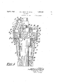
rllhis invention relates to rock drills, but chamber B is provided with a closure in the more particularly to valve mechanism for efform of a front cylinder washer D having a fecting the distribution of pressureiiuid to bore E for guiding a stem or extension F Vof the cylinder of rock drills of the hammer the piston C. A free exhaustn port G in the type, i l cylinder is controlled by the piston C.
The objects of the invention are to simplify f A suitable closure is provided for the rearthe construction of rock ydrills of this type, ward end of the piston chamber B inthe to insure an abundant admission of pressure form of a plate H. The plate H is disposed liuid to the cylinder with a minimum lift of Vinan enlarged bore J in the rearward end of wthe valve or valves, to lessen the chances of the cylinder A and forms a seat for a back injury to the valves, to render the valve mechhead K which may be secured to the cylinder 'anism inexpensive to manufacture Vand main* by any suitable means, such as side bolts (not tain, and to obtain a rapid and positive action shown). Y
of the valve mechanism and consequently also Preferably the back head K serves as a of the percussive element of the rock drill. housingfor the head L of a rifle bar O which Other objects will be in part obvious and extends through the plate H and slidably enpart pointed out hereinafter. gages the piston C in a well known manner.
In the drawings accompanying the vspeci- The rifle bar L may be provided with the lication and in which similar reference charusual spring pressed pawls P adapted to enacters refer to similar parts, gage teeth Q, of `a rotation ratchet R secured Figure l is a sectional elevation of a porlixedly in a recess S in the back head K in tion of a rock drill showing one form which which the head L also lies.
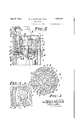
the invention may assume in practice, Y The parts so far described and their func- Figure 2 is a similar view showing a moditions are well known and are herein only fication of the invention, briey referred to in order to explain more Figure 3 is a transverse view taken through clearly the present invention and its appli- Figure 2 on the line 3-3 looking in the direccation and advantages.
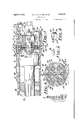
tion indicated by the arrows and showing the In accordance with the present invention a arrangement of the valve seats, valve chest designated generally by VT is dis- Figure 4 is an enlarged transverse view posed in the bore J to seat on an end wall U taken through Figure 2 on the line 4--4 lookin the cylinder A and in turn forms a seat for ing in the direction indicated by the arrows, the plate H. The valve chest T comprises a Figure is alongitudinal sectional elevarearward end plate V, a forward end plate tion of a rock drill showing a modified form W and an intermediate plate X. The plates of the invention, the view beingtaken through V, W and X as well as the plate H may be Figure 6 on the line 5-5 looking in the disecurely clamped in the operative position rection indicated by the arrows, by means of the side bolts which exert a pres- Figure 6 is atransverse view taken through sure on the back head. Any other suitable Figure 5 on the line 6 6 looking in the direcmeans may, however, be vprovided for maintion indicated by the arrows, and showing the ltaining these parts in the operative position.
arrangement of the valves, i The plate X may be a fiat plate of uniform Figure 7 is a perspective view of a valve, thickness throughout and is provided with and a plurality of valve chambers Y in which are Figure 8 is a similar view of a valve guide. disposed valves Z in the form of thin flat it Referring to the drawings and at first more disks or plates guided only on their periphparticularly to Figure l, A designates a cylinder having a piston chamber B in which is disposed a reciprocatory hammer piston C for delivering blows to a working implement (not shown). The front end of the piston eries by the chambers Y. At the rearward sides of the valve chambers Y and on the plate V are valve seats b which act as stops for the valves Z.
The valve seats b are preferably of considerably smaller diameter than the valves Z so that an annular area of the rearward ends of the valves Z will be at all times exposed to pressure fluid. Similarly, the plate W is provided with valve seats o for the front ends of the valves Z7 said valve seats 0 being of the same proportions and conformation as the valve seats b so that a similar annular area on the front surfaces of the valves Z will also be constantly subjected to live pressure iiuid.
By thus forming the Valve seats b and c, shoulders cl and e will be formed around the valve seats b and o and said shoulders are only slightly spaced from the plate X to assure the restriction of the pressure fluid entering the valve chambers Y.
In the construction shown inlet passages f lead from the rearward ends of the valve chambers Y through the plate V to the rearward end o-f the piston chamber B. Front inlet passages g lead from the valve seats c through the plate W and through the cylinder A to the front -end of the piston chamber B for conveying pressure fluid thereto to impel the piston C in a rearwardly direction.
The pressure fluid utilized for actuating the piston C may be introduced into the drill yat a point adjacent a throttle valve 71. disposed in lthis instance in a valve chamber j in the back head K. The throttle valve h is provided with a central chamber la and has a port 0 to afford communication between the chamber 7c and a passage p leading from the throttle valve chamber to a supply reservoir g, located in this instance in the back head K. Pressure introduced into the supply reservoir g is rconveyed through the valve chest by supply passages r which communicate at their other ends with a supply chamber 8 surrounding in this instance the valve chambers Y. The supply chamber is of annular shape and is of a depth to lie both below and above the plate X and of a width to communicate-with each vave chamber Y at opposite sides thereof so that in effect it forms a portion of each valve chamber. This assures an abundant supply of pressure fluid to each inlet passage immediately after the valves shift. The supply passages r however, extend to the lowermost point of the supply chamber sothat both sides of the valves Z will be constantly exposed to pressure fluid `in a manner to be more fully described hereinafter.
In order to assure compactness and a minimum weight of the rock drill the plates X, V and `W comprising the valve chest are provided with bores t of the same diameter as the piston chamber B for which the bores t form a continuation so that the piston C may reciprocate through the valve chest.
The operation of the form of the invention so far described is as follows: Vith the throttle valve h in the open position and the valves Z and the piston C in the positions illustrated, pressure fluid flowing from the supply reservoir q through the supply passages r into the supply chamber' s will flow through the restricted spaces between the shoulders (l and the rearward surface of the plate X into the valve chambers Y and thence through the rearward inlet passages f into the rearward end of the piston chamber B to impel the piston C forwardly against the working implement. While the valves are in the position described the annular areas of the valves Z lying outside of the valve seats c are exposed to live pressure fluid.
During the passage of pressure fluid into the rearward end of the piston chamber B the entire rearward surfaces of the valves Z are exposed to pressure fluid so that the valves Z will remain firmly seated on the valve seats c. The valves Z will remain in this position until the piston C approaches the forward end of the piston chamber B.
is the piston `C covers the exhaust port Gr Vthe air in the front end of the piston chamber B will be compressed and such compression flowing through the inlet passages g will act against the forward surfaces of the valves Z tending to throw the valves Z rearwardly against the seats Shortly prior to the time the piston C delivers its blow against the working implement the free exhaust port G will be uncovered by the piston. Pressure fluid used for throwing the piston C forwardly will then exhaust to the atmosphere through the exhaust `ports G. This will cause a reduction in pressure on the rearward ends of the valves Z due to the manner in which the flow of pressure fluid into the valve chambers is restricted. The valves will then be thrown rearwardly against the seats b by the pressure fluid and the compression acting against the forward surfaces of the valve.
l/Vith the valves Z thus reversed pressure fluid will flow into the valve chambers Y through the restricted spaces between the shoulders e and the forward surface of the 'plate X into the valve chambers Y, thence through the linlet passages g into the front end of the piston chamber B to impel the piston C rearwardly.
The air entrapped in the rearward end of the piston chamber by the piston will of course also be compressed and will act against therearward surfaces of the valves Z. At the same time the areas of the valves lying outside of the seats are exposed to live pressure fluid. After the piston C has travelled rearwardly a sufficient distance to uncover the exhaust port G the pressure Huid will be exhausted from the front end of the piston chamber to the atmosphere. This will cause a sudden drop of pressure in the forward surfaces of the valves Z and the valves will thence be moved forwardly against the seats against the rearward sur-faces of the valves.
In the modification shown in Figures 2 to 4 inclusive, the cylinder A is provided at its rearward end with a bore u of sufficient depth to receive the valve chest o and a rotation ratchet 'w disposed in this instance on the valve chest o. The rotation ratchet w forms aseat for a back head which may be secured to the cylinder A in any well known manner. The valve chest o comprises forward and rearward end plates g/ and .e respectively and an intermediate plate 2. Seated on the rearward .surface of the plate z is a plate 3 to form a seat for the rotation ratchet w and for the head L of the riiie bar O. In this modification the back head at is also provided with a supply reservoir 4 which is in constant communication with the supply chamber s through supply passages rleading through the rotation ratchet w and the plates 3, z, 2 and y.
. In the construction shown in this modification the plate y forms a closure for the rearward end of the piston chamber B and pressure fluid is admitted to the front end of the piston chamber through an inlet passage 6 in the cylinder A communicating at its rearward end with a chamber 7 preferably formed in the plates 3 and a. From the chamber 7 to the ends of the valve chambers Y lead passages 8 for conveying pressure fluid from the rearward ends of the valve chambers Y to the chamber 7. The admission of pressure fluid to the rearward ends of the piston chamber B is effected through Vinlet passages 9 formed in the plate g/ and opening directly into the piston chamber B.
The plates comprising the valve chamber o such as the plates y, e, 2 and 3 are each provided with bores 10 to receive the rifle bar O and form a guide therefor. rIhe construction of the plates comprising the valve chambers and the valve seats in this modification is the same as that described in connection with the previous modification. The operation is also practically the same and differs principally in that the chamber 7 may act as an expansion chamber so that as the piston C approaches the front end of the piston chamber an ample chamber is provided for the air compressed in the front end of the piston chamber and the piston C may therefore deliver a heavy blow against the working implement before sufficient pressure fluid is admitted to the front end of the piston chamber to retard the forward movement of the piston. Y
The general arrangement of the parts comprising the modification shown in Figures 5 to 8 inclusive is substantially like that illustrated in Figure 2, that is, the rotation ratchet 'w is disposed in a bore 11 in the rearward end of the cylinder A and forms a seat for the back head m which also has a supply reservoir 4. Disposed -in the bore 11 and forwardly of the rotation ratchet lw is a plate 12 which forms a seat for the front end of the rotation ratchet w and for the head L of the riiie bar O.
The plate 12 is in turn seated on a plate 13 in the bore 11. The plate 13 forms a por- In this construction the plates 13 and 14 are provided in their adjacent surfaces with annular supply chambers 15 which communicate with the supply reservoir 4 through supply passages 16 in the rotation ratchet lw and the plates 12 and 13. The supply chambers 15 are formed in both the plates 13 and 14 so that the opposite sides of the valves Z andthe valve chambers Y may be constantly exposed to pressure fluid.
On the inner surface of the annular supply passages 15 are disposed valve guides 17 to receive the valves Z. In the peripheries of the valve guides 17 are rows of small ports 18, the ports 18 being located valve seat b and the ports 19 adjacent the valve seats c. These ports 18 and 19 are of such cross sectional area that the pressure iuid is somewhat restricted during its passage from the valve chamber Y j Preferably the valve guides 17 are of a height equal to the depth of the supply chambers 15 so that when the parts are assembled in the drill the valve gui-des 17 will be heldagainst endwise movement. The pressure fluid is in this instance conveyed to the rearward end of the piston chamber B by inlet passages 2O formed in the plate 14 adjacent the supply chambers 15 into the and opening at their inlet ends into the valve seats 0. The admission of pressure fluid to the front end of the piston chamber B is effected through an inlet passage 21 formed inthe cylinder A and communicating at its rearward yend with a chamber 22 formed in the adjacent surfaces of the plates 12 and 13. From the chamber 22 lead passages 23 for conveying pressure fluid from the rearward ends of the valve chambers Y tothe chamber 22.
The operation of this modification is substantially like that previously described and this modification differs from the prior described modifications ner in which the valves Z are guided.
7e claim:
1. In a fluid actuated rock drill, the combination of a cylinder and a piston in the cylinder, an exhaust port for the cylinder, a valve chesthaving a plurality of and a supply passage, distributing valves in the valve chambers, a bore in the valve chest to slidably receive the piston, inlet passages leading from the valve chamber to the cylprincipally in the manvalve chambers inder, and a valve in the valve chamber controlling communication between the supply and inlet passages.
2. In a uid actuated rock drill, the combination of a cylinder and a piston in the cylinder, an exhaust port for the cylinder, a valve chest in the cylinder having a plurality of valve chambers and a supply passage, distributing valves in the valve chambers, a bore in the valve chest to slidably receive the piston, inlet passages leading from the valve chamber to the cylinder, and a valve in the valve chamber controlling communication between the supply and inlet passages.
Y3. In a fluid actuated rock drill, the combination of a cylinder and a piston, an exhaust port for the cylinder, a rifle' bar for rotating the piston, a valve chest encircling the rifle bar and having a plurality of valve chambers, a supply passage allording communication between the valve chambers and a source of pressure fluid supply, inlet passages leading from the valve chambers to the cylinder, and valves in the valve chambers controlling communication between the supply and inlet passages.
il. In a fluid actuated. roclr drill, the combination of a cylinder and a piston, an exhaust port for the cylinder, a rifle bar for rotating -he piston and having a head, a valve chest encircling the rifle bar and forming a seat for the head, a plurality of valve chambers in the valve chest, a supply passage constantly conveying pressure fluid from a source of supply to the valve chambers, inlet passages leading from the valve chambers to the cylinder, and valves in the valve chambers for controlling the flow of pressure fluid from the supply passage to the inlet passages.
In a fluid actuated rock drill, the combination of a cylinder having a piston chamber and a piston in the piston chamber, a'rifle bar for rotating the piston, a valve chest in the cylinder encircling the rifle bar and having a bore forming a continuation of the piston chamber, a plurality of valve chambers in the valve chest, a supply passage for conveying pressure fluid from a source of supply to the valve chambers, inlet passages leading from the valve chambers to the piston chamber, and valves in the valve chambers controlling the flow of pressure fluid from the supply passage to the inlet passages.
6. In a iluid actuated rock drill, the combination of a cylinder' having a piston chamber and a piston in the piston chamber, a rifle bar for rotating the piston, a head on the rifle bar, a valve chest in the cylinder forwardly of the head and having a bore to form a continuation of the piston chamber, a plurality of valve chambers in the valve chest, a supply passage conveying pressure fluid from a source of supply to the valve chambers, means for restricting the flow of pressure fluid into the valve chambers, inlet passages leading from the ends of the valve chambers to the corresponding ends of the piston chamber, and valves in the valve chambers alternating between the inlet passages for controlling communication between said inlet passages and the supply passage.
7 In a fluid actuated rock drill, the combination of a cylinder having a piston chamber and an exhaust port and a piston in the pis- -ton chamber controlling the exhaust port, .a
valve chest in the cylinder comprising a pair of end plates and an intermediate plate, a plurality of valve chambers in the intermediate plate, valve seats on the end plates in coaxial alignment with the valve chambers, a supply passage leading from a source of pressure fluid supply to the valve chambers and in constant communication therewith, means for restricting the flow of pressure fluid from the supply passage to the valve chambers, inlet passages leading from the valve chambers to the ends of the piston chamber, and disk valves in the valve chambers for controlling the flow of pressure fluid from the supply passage to the inlet passages.
In testimony whereof we have signed this specification.
WILLIAM A. SMITH, SR.
WILLIAM A. SMITH, JR.
Priority Applications (1)
| Application Number | Priority Date | Filing Date | Title |
|---|---|---|---|
| US299493A US1852591A (en) | 1928-08-14 | 1928-08-14 | Rock drill |
Applications Claiming Priority (1)
| Application Number | Priority Date | Filing Date | Title |
|---|---|---|---|
| US299493A US1852591A (en) | 1928-08-14 | 1928-08-14 | Rock drill |
Publications (1)
| Publication Number | Publication Date |
|---|---|
| US1852591A true US1852591A (en) | 1932-04-05 |
Family
ID=23155046
Family Applications (1)
| Application Number | Title | Priority Date | Filing Date |
|---|---|---|---|
| US299493A Expired - Lifetime US1852591A (en) | 1928-08-14 | 1928-08-14 | Rock drill |
Country Status (1)
| Country | Link |
|---|---|
| US (1) | US1852591A (en) |
Cited By (2)
| Publication number | Priority date | Publication date | Assignee | Title |
|---|---|---|---|---|
| US3198439A (en) * | 1963-05-10 | 1965-08-03 | Vilbiss Co | Airless spray gun with variable output |
| US3935789A (en) * | 1974-07-19 | 1976-02-03 | The Black And Decker Manufacturing Company | Reversing valve |
-
1928
- 1928-08-14 US US299493A patent/US1852591A/en not_active Expired - Lifetime
Cited By (2)
| Publication number | Priority date | Publication date | Assignee | Title |
|---|---|---|---|---|
| US3198439A (en) * | 1963-05-10 | 1965-08-03 | Vilbiss Co | Airless spray gun with variable output |
| US3935789A (en) * | 1974-07-19 | 1976-02-03 | The Black And Decker Manufacturing Company | Reversing valve |
Similar Documents
| Publication | Publication Date | Title |
|---|---|---|
| US1852591A (en) | Rock drill | |
| US1773366A (en) | Rotation mechanism for rock drills | |
| US1802987A (en) | Rock drill | |
| US1874130A (en) | Rock drill | |
| US1593606A (en) | Rock drill | |
| US2224861A (en) | Pressure fluid motor | |
| US2108989A (en) | Rotation mechanism | |
| US750331A (en) | Steam-actuated valve | |
| US1711811A (en) | Valve for rock drills | |
| US2162036A (en) | Rock drill | |
| US1196040A (en) | smith | |
| US1734985A (en) | Valve for rock drills | |
| US1855206A (en) | Valve for rock drills | |
| US1807800A (en) | Valve eor rock drills | |
| US1554984A (en) | Fluid-actuated distributing valve for rock drills | |
| US2110331A (en) | Pressure fluid motor | |
| US1750323A (en) | Valve for rock drills | |
| US1770676A (en) | Valve mechanism for rock drills | |
| US1771181A (en) | Valve for rock drills | |
| US1815166A (en) | Valve for rock drills | |
| US1946989A (en) | Valve for rock drills | |
| US1688633A (en) | Valve for rock drills | |
| US1852593A (en) | Valve for rock drills | |
| US2234348A (en) | Valve for rock drills | |
| US1740122A (en) | Rock drill |