US1852589A - Window construction - Google Patents
Window construction Download PDFInfo
- Publication number
- US1852589A US1852589A US437882A US43788230A US1852589A US 1852589 A US1852589 A US 1852589A US 437882 A US437882 A US 437882A US 43788230 A US43788230 A US 43788230A US 1852589 A US1852589 A US 1852589A
- Authority
- US
- United States
- Prior art keywords
- opening
- closure
- latch
- frame
- section
- Prior art date
- Legal status (The legal status is an assumption and is not a legal conclusion. Google has not performed a legal analysis and makes no representation as to the accuracy of the status listed.)
- Expired - Lifetime
Links
- 238000010276 construction Methods 0.000 title description 8
- 238000005192 partition Methods 0.000 description 19
- 239000000945 filler Substances 0.000 description 11
- 239000002184 metal Substances 0.000 description 10
- 230000004048 modification Effects 0.000 description 8
- 238000012986 modification Methods 0.000 description 8
- 230000000153 supplemental effect Effects 0.000 description 6
- 230000006835 compression Effects 0.000 description 3
- 238000007906 compression Methods 0.000 description 3
- 239000011521 glass Substances 0.000 description 2
- 230000002787 reinforcement Effects 0.000 description 2
- 230000006978 adaptation Effects 0.000 description 1
- 230000000881 depressing effect Effects 0.000 description 1
- 230000000694 effects Effects 0.000 description 1
- JEIPFZHSYJVQDO-UHFFFAOYSA-N iron(III) oxide Inorganic materials O=[Fe]O[Fe]=O JEIPFZHSYJVQDO-UHFFFAOYSA-N 0.000 description 1
- 239000000463 material Substances 0.000 description 1
- 230000009972 noncorrosive effect Effects 0.000 description 1
- 230000003014 reinforcing effect Effects 0.000 description 1
- 239000011435 rock Substances 0.000 description 1
- 238000005096 rolling process Methods 0.000 description 1
- 239000004636 vulcanized rubber Substances 0.000 description 1
Images
Classifications
-
- E—FIXED CONSTRUCTIONS
- E06—DOORS, WINDOWS, SHUTTERS, OR ROLLER BLINDS IN GENERAL; LADDERS
- E06B—FIXED OR MOVABLE CLOSURES FOR OPENINGS IN BUILDINGS, VEHICLES, FENCES OR LIKE ENCLOSURES IN GENERAL, e.g. DOORS, WINDOWS, BLINDS, GATES
- E06B3/00—Window sashes, door leaves, or like elements for closing wall or like openings; Layout of fixed or moving closures, e.g. windows in wall or like openings; Features of rigidly-mounted outer frames relating to the mounting of wing frames
- E06B3/32—Arrangements of wings characterised by the manner of movement; Arrangements of movable wings in openings; Features of wings or frames relating solely to the manner of movement of the wing
- E06B3/34—Arrangements of wings characterised by the manner of movement; Arrangements of movable wings in openings; Features of wings or frames relating solely to the manner of movement of the wing with only one kind of movement
- E06B3/42—Sliding wings; Details of frames with respect to guiding
- E06B3/44—Vertically-sliding wings
- E06B2003/4438—Vertically-sliding wings characterised by the material used for the frames
- E06B2003/4446—Wood
Definitions
- This invention relates to window constructions, and more particularly to that kind in which the sashes or frames carrying the glass Y 4panels or panes are slidably mounted and counterbalanced in the usual manner by weighted sash cords or the like, the object of the invention being to improve the constructionby providing for removing the sashes from their guideways in the window frame but without detaching the sashes from their weighted counterbalancing cords, so that the glass panels or panes may be conveniently y washed on both their inner and outer sides from theinside of a room; to provide for readily applying the invention to the ordinary standard window structure, either during or after the course of construction thereof; and to attain certain other advantages as will more fully hereinafter appear.
- the invention consists broadly in making a portion of the window frame detachable in the region of the vertical guideways for the sashes at one side of the frame whereby both the upper and lower sashes may be moved edgewise into the opening after the removable portion is detached, whereby to withdraw the opposite edge por- Iions of the sashes from their respective guideways at the opposite side of the frame so that the sashes are permitted to swing freely from their counterb-alancing cords and held by the operator in any convenient position, at will.
- the invention further consists in the parts and combinations and arrangements of parts lq stantially on theline 3-'-3 of Fig. 1;
- Fig. 4 is a fragmentary horizontal section on the line 4.--4 of Fig. 3; p
- Fig. 5 is a fragmentary view, on an enlarged scale, illustrating details of the detachable elements for closing the opening in the window frame at the side of the frame where the window sashes are moved to effect their release from their respective guideways in the frame; y
- Fig. 6 is a section, taken on or about the line 6 6 of Fig. 5;
- Fig. 7 is a view, similar to Fig. 5, illustrating a modification of the closure elements for the opening in the side of the window frame;
- Fig. 8 is a section on the line 88 of Fig. 7, with the intermediate portion of the closure member removed;
- Fig. 9 is a horizontal section, taken -substantially on the line 9 9 of Fig. 7
- Fig. 10 is a fragmentary vertical section on the line 10-10 of Fig. 7;
- Fig. 11 is a fragmentary section, illustrat ing a modification of the latch device of the removable elements.
- the numeral 15 designates the vertical side members of an ordinary window frame, said frame having the usual sill 16 and top cross member 17.
- the side members 15 of the frame are provided with the usual vertical guideways 18 and 19 for the upper and lower sashes 2O and 21, the sashes having the usual sash cords 22 attached to their upper end portions, said cords passing over the grooved pulleys 23 near the top of the window frame and being provided with the usual counterbalancing weights 24 which work in the vertical spaces 25 provided therefor in the side members 15 of the frame.
- the guideways 18 and 19 for the sashes 2O and 21 are produced by providing a vertical parting strip 26 on the partitions 27, which constitute the bottoms of said guideways or channels in which the sashes slide.
- a vertically elongated opening 28 which is of a length a little greater than the over all vertical dimension of each of the sashes 20 and 21, and
- this opening 28 is located slightly above the sill 16, as at 29, and its upper end, of course, necessarily terminates some distance above the top end of the lower sash 21, as at 30. is shown more clearly in Figs. 2 and 5 of the drawings, the opening 28 extends transversely into both of the guideways 18 and 19 and, of course, that portion of the parting strip 26 in the region of the opening is removed.
- a supplemental strip 31 which Ais mounted on a closure member 32, which latter is fitted removably in the opening 28, as will presently be described in detail, said supplemental strip 31 completing the continuity of the strip 26 and the cover member 32 completing the continuity of the partition 27, it being flush with both the inner and outer faces of said partition when in place.
- the closure member 32 is made in two separate sections, the upper section 33 thereof being obviously inserted first in a lower portion of the opening 28, below the bottom ends of the sashes and 21, at which time, of course, both sashes are raised to their uppermost positions, but their lower ends are in a horizontal plane considerably below that ofthe upper end of said opening 28.
- This upper section 33 is first inserted and then slid to the upper endof the'opening 28 and the lower section 34 of said closure member is next inserted to close the lower portion of the opening.
- the upper section 33 of the closure member 32 is preferably composed of a rectangular metal plate 35 which is seated in a rabbeted marginal portion 28 of the partition 27 at the .upper end and opposite sides of the opening 28, so as to be flush with the outer face of Said partition.
- a wooden filler member 36 which is of a width corresponding to the 'l width ofthe opening 28 and of a thickness so that it is flush with the inner face of the partition 27 when in place, is attached to the inner face of said plate 35.
- said section is provided on its inner side with a longitudinal groove 36 near its upper end, in which a latch member 37 is loosely fitted.
- This latch member is mounted on a screw-bolt or threaded stud 38, said stud having a head 39 which is preferably beveled marginally so as to seat in a countersunk aperture in the plate 35, through which aperture the screw-bolt or stud 39 is inserted and engaged in a screw-threaded aperture provided therefor in the latch member 37, there being a compression spring 40 coiled about said bolt or stud 38 and interposed between the plate 35 and the latch member 37.
- a spring 42 Located in a recess 41 in the wooden filler member 36 and interposed between the plate 35 and the end portion of said latch member 37 is a spring 42, said spring 42 being constantly under compression and acting to rock said latch member with the stud 38 as a fulcrum and thereby move the portion of the latch member below the stud away from the bottom of the groove in the filler member 36 in which said latch member is located.
- the upper end portion of the latch member which is preferably beveled on its inner face, as at 43, is pressed tightly but releasably against a shoulder 44 at the upper end of the opening 28 in the partition 27, said shoulder being preferably covered with a suitable sheet ⁇ metal wear plate 45.
- the screw-bolt or kthreaded stud 38 By adjusting the screw-bolt or kthreaded stud 38 longitudinally in its opening in the latch member 37, the latter may be variably spaced from the plate 35, at will, so as to assure a snug Contact of the beveled end portion 43 of said latch member with the shoulder 44, there being a certain amount of clearance provided between the bottom of the groove 36 and the adjacent longitudinal face of said latch member 37.
- a channel shaped extension 46 formed preferably of sheet metal, in the upper portion of which is housed a transverse tubular member 47 which is preferably square in cross-section and has a pair of oppositely disposed latch bolts 48 slidable longitudinally in its opposite end portions, said latch bolts being adapted to engage in rectangular notched keepers 49 provided therefor on opposite sides of the opening 28, said keepers each comprising a plate 50, as shown more clearly in Fig. 1 of the drawings, the notch in the plate 50 registering cooperatively with a corresponding recess provided in the adjacent portion of the window frame, as shown more clearly in Fig. 5.
- the latch bolts 48 are normally held in extended position by lever members 51, which are operably crossed on a pivot 52 and are normally held apart by compression spring 53, said spring being interposed between upstanding lugs 54 provided therefor at the outer marginal portions of said lever members 51.
- the spring 53 is coiled about a rod 55 which is fitted loosely at its opposite ends in apertures provided therefor in said lugs 54, said rod 55 extending approximately from side wall to side wall of said channeled housing 46.
- said lever members 51 are provided with handle eXtensions 56, said handle extensions preferably having marginal wings 57 for convenience in manipulating said elements. It is further preferable to loosely mount the tubular member 47 in the housing 46 and extend the latch bolts through slots inthe side walls of said housing, and to provide leaf springs 58 which are secured at their ends, as at 59, toV the bottom wall of the housing 46 and have the opposite end portions arranged to bear against the tubular member 47 and yieldably press the same away from the bottom of said housing.
- the tubular member 47 isv provided with a central screw-threaded opening 60 which is engaged by a screw 61 inserted through an opening provided therefor in the metal plate 62 of the lower section 34 of the closure member 32, said plate 62 being similar to the plate 35 on the upper section 33 and having a wooden filler member 63 secured to its inner face, similar to the filler member 36.
- a screw 61 Bytightening the screw 61 the tubular member 47 is drawn towards the plate 62 and the projected end portions of the latch bolts 48 are accordingly brought into engagement with the bottoms of the keeper notches 49 at the opposite sides of the opening 28 and the plate 62 is obviously seated tightly in the rabbeted portions 28 in the outer face of the partition 27 about the marginal portions surrounding said opening 28.
- a latch element 64 similar to the element .37 at the upper end of the upper section 33 of the closure member.
- the lower end portion of this latch element 64 projects below the end of the filler member 63, as at 65, and engages behind the shouldered portion 66 of the partition 27 at the lower end of the opening 28, said shouldered portion being preferably provided with a sheet metal reinforcement 67 similar to the reinforcement 45 at the upper end of said opening 28.
- closure member 32 is readily attached and detached, at will, and when in place is flush with both the outer and inner faces of the partition 27 so that there is no interference with the sliding of the sashes 2O and 21 in the vertical guideways 18 and 19, nor any projection or recess produced in the vertical space or shaft 25 which might be engaged by the counterbalancing weights 24 and interfere with the movement thereof.
- the supplemental parting strip 31 on the closure member 32 comprises an upper section 68 and a lower section 69, respectively secured to the upper and lower sections 33 and 34 of said closure member.
- These supplemental parting strip sections are preferably tubular members of rectangular crosssection Vand composed of non-corrosive or rust-resistant metal.
- the meeting end portions of the two parting strip members 68 and 69 are beveled, as at 7l, and more clearly shown in Fig. 6 of the drawings. So, too, the lower end portion 72 of the strip member 69 is beveled where it meets the adjacent portion 26 of the Vregular parting strip on the outer face of the partition 27.
- FIG. 7 A modification of the closure member 32 is illustrated in Figs. 7 to 11, inclusive, of the drawings.
- the closure member designated by the reference numeral 7 3
- the closure member is made in a single section. As shown, it comprises a sheet metal outer plate whose lower portion 74 fits into the rabbeted marginal portion of the partition 27 about the ⁇ opening' 28 and whose upper portion 75 is reduced in width so as to fit between the parallel leg portions 76 of a substantially U- shaped plate 77 which is fastened, as by the screws 78, in the rabbeted portion'of the partition 27 about theupper portion of the opening 28, the inner marginal portions of said legs 76 and the base portion of the plate 77 overhanging the opening 28.
- the closure member 73 is further provided with a filler member 79, similar to the filler members 36 and 63, except that it is in a single piece corresponding in length and breadth to the opening 28.
- This filler member 79 projects marginally beyond the side and end edges of theV upper portion of the sheet metal outer plate of the closure member 73, thereby producing a rabbet into which the adjacent side and base margins of the plate 77 seat when the closure member is in place. As shown in Figs.
- the outer plate of the closure member 73 is provided with oppositely disposed rounded projections 8O on its inner face and at its opposite side margins at the base of the restricted upper ⁇ portion of the outer plate, said rounded projections 80 being preferably formed by rolling the portion ofv the metal comprising the outer plate, as shown more clearly in Fig. 10.
- These projections 80 are adapted to enter undercut notched portions 81 at opposite sides of the opening 28 in the partition 27, the adjacent portions of said partition being provided with corresponding notched escutcheons or reinforcing plates 82.
- a supplemental parting strip 83 On the outer face of the closure member -7 3 is a supplemental parting strip 83, preferably'composed of similar rectangular tubing as in the first herein described modification, said supplemental parting strip being closed at its ends by plugs 84, and the upper endof-said strip where it meets the regular parting strip 26 is preferably beveled, as at 85.
- the closure member 7 3 is held in place by the interlocking engagement of the fulcrum members 80 in the notches 81 and the engagement of the rabbeted upper portion of said member 73 with the substantially Ueshaped plate 77, and a releasable latching device comprising a sliding rod or bolt member 86 Vwhich is mounted in the lowerportion of the ⁇ tubular partingV strip 83", as shown more clearly in Fig. 8 of the drawings.
- the lower end portion of the bolt 86 slides through the plug 84and a right angular end portion 87 of a removable latch plate 88, said lower end portion of the bolt engaging in a recess 89 provided therefor in the sill portion 16' of the window frame, said rod being actuated by a manipulating finger or extension 90 which works through a slot 91 in a depression 92 provided therefor in the latch plateV 88.
- a manipulating finger or extension 90 which works through a slot 91 in a depression 92 provided therefor in the latch plateV 88.
- the latch bolt 93 comprises a rectangularbody portion corresponding to the interior cross-section of the tubular parting strip member 83, and has an inwardly offset angular extension 94 which fits into a recess 95 in the partition 27 and behind a retaininfY plate or keeper' 96 provided on the outer Vface ofthe partition in connection with said recess.
- Said bolt 93 is manipulated by a fingerpiece in a manner similar to the hereinbefore described bolt 86, and it is preferably provided with a leaf spring 97 fitted in alongitudinally slotted portion 98 of the bolt and bearing against the outer plate of the closure member 73 through a slot 99 provided therefor in the bottom wall of the tubular parting strip 83.
- a similar opening of lesser dimensions may be provided, as at '100, for gaining access to the sash weights at that side of the frame, said opening being normally closed by a closure comprising an outer plate 101 and a filler 102, the outer plate having a parting strip member 103 thereon.
- said members are preferably corrugated or longitudinally grooved, as at 104, in their inner faces which engage the outer metal plates and, while the particular structures herein shown and described embody practical adaptations of the invention, it is understood that many modifications may be made in the general arrangements, as well as in the details of structure, without departing from the spirit and scope of the invention as defined by the appended claims. The invention, therefore, is not limited to the specific construction and arrangement shown in the accompanying drawings.
- a window structure comprising a frame having a guideway for av sliding sash, said guideway being provided with a longitudinally elongated opening of dimensions to receive the sash edgewise therein, a removable closure panel for said opening adapted when in place to complete the continuity of said guideway in the frame, means at the upper and lower ends of said closure panel for releasably locking the panel in place and transversely effective latching means intermediate its ends for releasably securing said closure panel in place.
- a window structure comprising a frame having a guideway for the edge portion of a slidable sash, a portion of said guideway being removed to afford a longitudinally eX- tending opening of length and breadth dimensions to receive the sash edgewise therein, the marginal portions of said frame around said opening being rabbeted, a removable closure panel for said opening, said panel comprising a sheet metal front plate seated in said rabbeted portions of the frame flush with the face of the guideway, its outer face completing the continuity of the guideway, a Vreenforcing backing on said front panel plate comprising a rectangular wooden strip insertable in said opening, and means for releasably securing said closure panel in place.
- a window structure comprising a frame having parallel guideways in its vertical side member,upper and lower sashes having their vertical edge portions respectively slidably mounted in said guideways, contiguous lower portions of said guideways extending transversely on opposite sides of the parting strip bein removed so as to liointl'v provide an elongated opening of length' and breadth dimensions suiiicient to receive either of said sashes edgewise therein, the upper end of said opening terminating above the upper end of the lower sash when in lowered position and also above the lower end of the upper sash in its raised position, a sectional closure panel for said opening, said panel when in place being flush with the faces of the guideways, means for releasably securing the upper end of the upper panel section to the adjacent edge portion of the frame, similar means for securing the lower end of the lower panel section in place, means at the upper end of the lower section for releasably engaging the meeting lower end of the upper section, and transversely acting means for re
- a window Jframe having a rectangular longitudinal opening in the sash slideway thereof, said opening being of length and breadth dimensions whereby to receive the sash edgewise therein, and a closure for said opening to complete the continuity of the slideway, said closure comprising separable upper and lower sections, said frame at the upper and lower ends of said opening and the corresponding end portions of the closure being arranged for releasably interlocking engagement, the lower end portion of the upper closure section having transversely disposed latch elements retractibly engageable in keeper openings in the adjacent portions of the frame at opposite sides of said opening, and means for detachably securing the meeting end portions of said upper and lower closure sections.
- a window frame having a rectangular longitudinal opening in the sash slideway thereof, said opening being of length and breadth dimensions whereby to receive the sash edgewise therein, and a closure for said opening to complete the continuity of the slideway, said closure comprising separable upper and lower sections, said frame having shoulder portions at the upper and lower ends of said opening, resiliently supported latch elements respectively on the upper end portion of the upper closure section and the lower end portion of the lower closure section for engagement with said shoulder portions of the frame, the lower end portion of said upper closure section being chambered and having oppositely disposed transversely acting latch members retractibly engageable in keeper openings provided therefor in the adjacent portions of the frame at opposite sides of said opening therein, holding and retracting means for said latch elements comprising cooperating spring-pressed lever members, and means for detachably securing together the meeting end portions of said upper and lower closure sections.
- a window frame having a rectangular longitudinal opening in its sash slideway, said frame having shoulder portions at the upper and lower ends of said opening, and a closure comprising cooperating upper and lower sections insertable in said opening to complete the continuity of the sash slideway of the frame, latch means at the upper end of the upper closure section comprising a longitudinally disposed member movably fitted in a grove provided therefor in said closure section, a resilient and pivotal support for said latch member and a separate spring element coacting with said latch ele-
Landscapes
- Engineering & Computer Science (AREA)
- Civil Engineering (AREA)
- Structural Engineering (AREA)
- Door And Window Frames Mounted To Openings (AREA)
Description
April `5, 1932- A. sERRlTELLA f 1,852,589
, WINDOW CONSTRUCTION Filed March 21, 1930 4 Sheets-Sheet 1 April 5, 1932.
A. sERRiTE| LA WINDOW CONSTRUCTION Filed March 2l, 1930 yzllessesr.'
4 Sheets-Sheet 2 www Ummm| IIHIIW mmm April 5, 1932- A. SERRITELLA 1,852,589
WINDOW CONSTRUCTION A` SERRITELLA WINDOW CONSTRUCTION April s, 1932.
4 Sheets-Sheet 4 f Filed March 21, 1950 7 In f Patented Apr. 5, 1932 PATENT OFFICE ANTONIO SERRITELLA, OF CHICAGO, ILLINOIS WINDOW CON$TRU CTION Application filed March 21,1930. serial No. 437,882.
This invention relates to window constructions, and more particularly to that kind in which the sashes or frames carrying the glass Y 4panels or panes are slidably mounted and counterbalanced in the usual manner by weighted sash cords or the like, the object of the invention being to improve the constructionby providing for removing the sashes from their guideways in the window frame but without detaching the sashes from their weighted counterbalancing cords, so that the glass panels or panes may be conveniently y washed on both their inner and outer sides from theinside of a room; to provide for readily applying the invention to the ordinary standard window structure, either during or after the course of construction thereof; and to attain certain other advantages as will more fully hereinafter appear.
Generally stated, the invention consists broadly in making a portion of the window frame detachable in the region of the vertical guideways for the sashes at one side of the frame whereby both the upper and lower sashes may be moved edgewise into the opening after the removable portion is detached, whereby to withdraw the opposite edge por- Iions of the sashes from their respective guideways at the opposite side of the frame so that the sashes are permitted to swing freely from their counterb-alancing cords and held by the operator in any convenient position, at will. The invention further consists in the parts and combinations and arrangements of parts lq stantially on theline 3-'-3 of Fig. 1;
as hereinafter more fullyV described and Fig. 4 is a fragmentary horizontal section on the line 4.--4 of Fig. 3; p
Fig. 5 is a fragmentary view, on an enlarged scale, illustrating details of the detachable elements for closing the opening in the window frame at the side of the frame where the window sashes are moved to effect their release from their respective guideways in the frame; y
Fig. 6 is a section, taken on or about the line 6 6 of Fig. 5; Fig. 7 is a view, similar to Fig. 5, illustrating a modification of the closure elements for the opening in the side of the window frame; Fig. 8 is a section on the line 88 of Fig. 7, with the intermediate portion of the closure member removed; Fig. 9 is a horizontal section, taken -substantially on the line 9 9 of Fig. 7
Fig. 10 is a fragmentary vertical section on the line 10-10 of Fig. 7; and
Fig. 11 is a fragmentary section, illustrat ing a modification of the latch device of the removable elements.
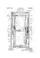
Referring now to the drawings, the numeral 15 designates the vertical side members of an ordinary window frame, said frame having the usual sill 16 and top cross member 17. The side members 15 of the frame are provided with the usual vertical guideways 18 and 19 for the upper and lower sashes 2O and 21, the sashes having the usual sash cords 22 attached to their upper end portions, said cords passing over the grooved pulleys 23 near the top of the window frame and being provided with the usual counterbalancing weights 24 which work in the vertical spaces 25 provided therefor in the side members 15 of the frame.
As in the ordinary standard window frame structure, the guideways 18 and 19 for the sashes 2O and 21 are produced by providing a vertical parting strip 26 on the partitions 27, which constitute the bottoms of said guideways or channels in which the sashes slide. In the partition 27 of one of the side frame members 15 is formed a vertically elongated opening 28 which is of a length a little greater than the over all vertical dimension of each of the sashes 20 and 21, and
also slightly wider than the thickness of each sash. The lower' end of this opening 28 is located slightly above the sill 16, as at 29, and its upper end, of course, necessarily terminates some distance above the top end of the lower sash 21, as at 30. is shown more clearly in Figs. 2 and 5 of the drawings, the opening 28 extends transversely into both of the guideways 18 and 19 and, of course, that portion of the parting strip 26 in the region of the opening is removed. This removed portion of the regular parting strip 26 is replaced by a supplemental strip 31 which Ais mounted on a closure member 32, which latter is fitted removably in the opening 28, as will presently be described in detail, said supplemental strip 31 completing the continuity of the strip 26 and the cover member 32 completing the continuity of the partition 27, it being flush with both the inner and outer faces of said partition when in place.
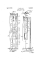
Preferably, for convenience in attaching and detaching the closure member 32, it is made in two separate sections, the upper section 33 thereof being obviously inserted first in a lower portion of the opening 28, below the bottom ends of the sashes and 21, at which time, of course, both sashes are raised to their uppermost positions, but their lower ends are in a horizontal plane considerably below that ofthe upper end of said opening 28. This upper section 33 is first inserted and then slid to the upper endof the'opening 28 and the lower section 34 of said closure member is next inserted to close the lower portion of the opening.
The upper section 33 of the closure member 32 is preferably composed of a rectangular metal plate 35 which is seated in a rabbeted marginal portion 28 of the partition 27 at the .upper end and opposite sides of the opening 28, so as to be flush with the outer face of Said partition. A wooden filler member 36 which is of a width corresponding to the 'l width ofthe opening 28 and of a thickness so that it is flush with the inner face of the partition 27 when in place, is attached to the inner face of said plate 35. In order to releasably secure the upper section 33 of the closure member 32 in engagement with the partition 37, said section is provided on its inner side with a longitudinal groove 36 near its upper end, in which a latch member 37 is loosely fitted. This latch member is mounted on a screw-bolt or threaded stud 38, said stud having a head 39 which is preferably beveled marginally so as to seat in a countersunk aperture in the plate 35, through which aperture the screw-bolt or stud 39 is inserted and engaged in a screw-threaded aperture provided therefor in the latch member 37, there being a compression spring 40 coiled about said bolt or stud 38 and interposed between the plate 35 and the latch member 37.
Located in a recess 41 in the wooden filler member 36 and interposed between the plate 35 and the end portion of said latch member 37 is a spring 42, said spring 42 being constantly under compression and acting to rock said latch member with the stud 38 as a fulcrum and thereby move the portion of the latch member below the stud away from the bottom of the groove in the filler member 36 in which said latch member is located. By this provision the upper end portion of the latch member, which is preferably beveled on its inner face, as at 43, is pressed tightly but releasably against a shoulder 44 at the upper end of the opening 28 in the partition 27, said shoulder being preferably covered with a suitable sheet `metal wear plate 45. By adjusting the screw-bolt or kthreaded stud 38 longitudinally in its opening in the latch member 37, the latter may be variably spaced from the plate 35, at will, so as to assure a snug Contact of the beveled end portion 43 of said latch member with the shoulder 44, there being a certain amount of clearance provided between the bottom of the groove 36 and the adjacent longitudinal face of said latch member 37.
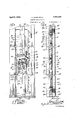
At the lower end of the upper member 33 is a channel shaped extension 46 formed preferably of sheet metal, in the upper portion of which is housed a transverse tubular member 47 which is preferably square in cross-section and has a pair of oppositely disposed latch bolts 48 slidable longitudinally in its opposite end portions, said latch bolts being adapted to engage in rectangular notched keepers 49 provided therefor on opposite sides of the opening 28, said keepers each comprising a plate 50, as shown more clearly in Fig. 1 of the drawings, the notch in the plate 50 registering cooperatively with a corresponding recess provided in the adjacent portion of the window frame, as shown more clearly in Fig. 5. The latch bolts 48 are normally held in extended position by lever members 51, which are operably crossed on a pivot 52 and are normally held apart by compression spring 53, said spring being interposed between upstanding lugs 54 provided therefor at the outer marginal portions of said lever members 51. Preferably, the spring 53 is coiled about a rod 55 which is fitted loosely at its opposite ends in apertures provided therefor in said lugs 54, said rod 55 extending approximately from side wall to side wall of said channeled housing 46.
For convenience in retracting the latch bolts 48 and withdrawing them from engagement with the keepers 49, said lever members 51 are provided with handle eXtensions 56, said handle extensions preferably having marginal wings 57 for convenience in manipulating said elements. It is further preferable to loosely mount the tubular member 47 in the housing 46 and extend the latch bolts through slots inthe side walls of said housing, and to provide leaf springs 58 which are secured at their ends, as at 59, toV the bottom wall of the housing 46 and have the opposite end portions arranged to bear against the tubular member 47 and yieldably press the same away from the bottom of said housing. Obviously, by this provision it is an easy matter to apply the upper section 3.3 to the opening 28 in that it is only necessary to first engage the latch 37 at the upper por tion with the shoulder 44 and then snap the lower portion into place, by pressing the member 33 bodily into the opening and then depressing the member 47 against the tension of the springs 58 so that the latch bolts 48 will readily engage the notched keepers 49, the springs 58 reacting to press the tubular member 47 outwardly.
The tubular member 47 isv provided with a central screw-threaded opening 60 which is engaged by a screw 61 inserted through an opening provided therefor in the metal plate 62 of the lower section 34 of the closure member 32, said plate 62 being similar to the plate 35 on the upper section 33 and having a wooden filler member 63 secured to its inner face, similar to the filler member 36. Bytightening the screw 61 the tubular member 47 is drawn towards the plate 62 and the projected end portions of the latch bolts 48 are accordingly brought into engagement with the bottoms of the keeper notches 49 at the opposite sides of the opening 28 and the plate 62 is obviously seated tightly in the rabbeted portions 28 in the outer face of the partition 27 about the marginal portions surrounding said opening 28. At the lower end of the lower section 34 of said closure member 32 is a latch element 64 similar to the element .37 at the upper end of the upper section 33 of the closure member. The lower end portion of this latch element 64 projects below the end of the filler member 63, as at 65, and engages behind the shouldered portion 66 of the partition 27 at the lower end of the opening 28, said shouldered portion being preferably provided with a sheet metal reinforcement 67 similar to the reinforcement 45 at the upper end of said opening 28.
From the foregoing description it is apparent that the closure member 32 is readily attached and detached, at will, and when in place is flush with both the outer and inner faces of the partition 27 so that there is no interference with the sliding of the sashes 2O and 21 in the vertical guideways 18 and 19, nor any projection or recess produced in the vertical space or shaft 25 which might be engaged by the counterbalancing weights 24 and interfere with the movement thereof.
The supplemental parting strip 31 on the closure member 32 comprises an upper section 68 and a lower section 69, respectively secured to the upper and lower sections 33 and 34 of said closure member. These supplemental parting strip sections are preferably tubular members of rectangular crosssection Vand composed of non-corrosive or rust-resistant metal.
69, as shown, are closed by plugs 70, preferably of vulcanized rubber, but, obviously, they may be made of any other suitable or desirable material. Also, the meeting end portions of the two parting strip members 68 and 69 are beveled, as at 7l, and more clearly shown in Fig. 6 of the drawings. So, too, the lower end portion 72 of the strip member 69 is beveled where it meets the adjacent portion 26 of the Vregular parting strip on the outer face of the partition 27.
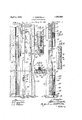
A modification of the closure member 32 is illustrated in Figs. 7 to 11, inclusive, of the drawings. In this modification the closure member, designated by the reference numeral 7 3, is made in a single section. As shown, it comprises a sheet metal outer plate whose lower portion 74 fits into the rabbeted marginal portion of the partition 27 about the `opening' 28 and whose upper portion 75 is reduced in width so as to fit between the parallel leg portions 76 of a substantially U- shaped plate 77 which is fastened, as by the screws 78, in the rabbeted portion'of the partition 27 about theupper portion of the opening 28, the inner marginal portions of said legs 76 and the base portion of the plate 77 overhanging the opening 28. The closure member 73 is further provided with a filler member 79, similar to the filler members 36 and 63, except that it is in a single piece corresponding in length and breadth to the opening 28. This filler member 79 projects marginally beyond the side and end edges of theV upper portion of the sheet metal outer plate of the closure member 73, thereby producing a rabbet into which the adjacent side and base margins of the plate 77 seat when the closure member is in place. As shown in Figs. 7 and 10 of the drawings, the outer plate of the closure member 73 is provided with oppositely disposed rounded projections 8O on its inner face and at its opposite side margins at the base of the restricted upper `portion of the outer plate, said rounded projections 80 being preferably formed by rolling the portion ofv the metal comprising the outer plate, as shown more clearly in Fig. 10. These projections 80 are adapted to enter undercut notched portions 81 at opposite sides of the opening 28 in the partition 27, the adjacent portions of said partition being provided with corresponding notched escutcheons or reinforcing plates 82.
In applying the closure member of this modication its upper end portion is'inserted angularly into the opening 28, that is, Ydiagonally and upwardly in the region of the notches 81 until the portions 8() enter said notches, whereupon the closure member is The end portions of said members 68 and swung into place -in said opening 28, said members 80vengaging in the notches 81 and affording the pivotal support for accomplishing this.
On the outer face of the closure member -7 3 is a supplemental parting strip 83, preferably'composed of similar rectangular tubing as in the first herein described modification, said supplemental parting strip being closed at its ends by plugs 84, and the upper endof-said strip where it meets the regular parting strip 26 is preferably beveled, as at 85.
The closure member 7 3 is held in place by the interlocking engagement of the fulcrum members 80 in the notches 81 and the engagement of the rabbeted upper portion of said member 73 with the substantially Ueshaped plate 77, and a releasable latching device comprising a sliding rod or bolt member 86 Vwhich is mounted in the lowerportion of the `tubular partingV strip 83", as shown more clearly in Fig. 8 of the drawings. The lower end portion of the bolt 86 slides through the plug 84and a right angular end portion 87 of a removable latch plate 88, said lower end portion of the bolt engaging in a recess 89 provided therefor in the sill portion 16' of the window frame, said rod being actuated by a manipulating finger or extension 90 which works through a slot 91 in a depression 92 provided therefor in the latch plateV 88. In Fig. 11 a further modification of the securing means for the closure member is illustrated. In this modification the latch bolt 93 comprises a rectangularbody portion corresponding to the interior cross-section of the tubular parting strip member 83, and has an inwardly offset angular extension 94 which fits into a recess 95 in the partition 27 and behind a retaininfY plate or keeper' 96 provided on the outer Vface ofthe partition in connection with said recess. Said bolt 93 is manipulated by a fingerpiece in a manner similar to the hereinbefore described bolt 86, and it is preferably provided with a leaf spring 97 fitted in alongitudinally slotted portion 98 of the bolt and bearing against the outer plate of the closure member 73 through a slot 99 provided therefor in the bottom wall of the tubular parting strip 83.
In the side of the window frame opposite to that in which the opening 28 is provided a similar opening of lesser dimensions may be provided, as at '100, for gaining access to the sash weights at that side of the frame, said opening being normally closed by a closure comprising an outer plate 101 and a filler 102, the outer plate having a parting strip member 103 thereon.
To prevent warping of the filler members 36. 63, 79 and 102, said members are preferably corrugated or longitudinally grooved, as at 104, in their inner faces which engage the outer metal plates and, whilethe particular structures herein shown and described embody practical adaptations of the invention, it is understood that many modifications may be made in the general arrangements, as well as in the details of structure, without departing from the spirit and scope of the invention as defined by the appended claims. The invention, therefore, is not limited to the specific construction and arrangement shown in the accompanying drawings.
Having thus described my invention, what I claim as new and desire to secure by Letters Patent is:
l. A window structure comprising a frame having a guideway for av sliding sash, said guideway being provided with a longitudinally elongated opening of dimensions to receive the sash edgewise therein, a removable closure panel for said opening adapted when in place to complete the continuity of said guideway in the frame, means at the upper and lower ends of said closure panel for releasably locking the panel in place and transversely effective latching means intermediate its ends for releasably securing said closure panel in place.
2. A window structure comprising a frame having a guideway for the edge portion of a slidable sash, a portion of said guideway being removed to afford a longitudinally eX- tending opening of length and breadth dimensions to receive the sash edgewise therein, the marginal portions of said frame around said opening being rabbeted, a removable closure panel for said opening, said panel comprising a sheet metal front plate seated in said rabbeted portions of the frame flush with the face of the guideway, its outer face completing the continuity of the guideway, a Vreenforcing backing on said front panel plate comprising a rectangular wooden strip insertable in said opening, and means for releasably securing said closure panel in place.
3. A window structure comprising a frame having parallel guideways in its vertical side member,upper and lower sashes having their vertical edge portions respectively slidably mounted in said guideways, contiguous lower portions of said guideways extending transversely on opposite sides of the parting strip bein removed so as to liointl'v provide an elongated opening of length' and breadth dimensions suiiicient to receive either of said sashes edgewise therein, the upper end of said opening terminating above the upper end of the lower sash when in lowered position and also above the lower end of the upper sash in its raised position, a sectional closure panel for said opening, said panel when in place being flush with the faces of the guideways, means for releasably securing the upper end of the upper panel section to the adjacent edge portion of the frame, similar means for securing the lower end of the lower panel section in place, means at the upper end of the lower section for releasably engaging the meeting lower end of the upper section, and transversely acting means for releasably engaging the meeting end portions of said upper and lower panel sections with the adjacent portions of the frame whereby to normally retain said panel section in place.
4. A window Jframe having a rectangular longitudinal opening in the sash slideway thereof, said opening being of length and breadth dimensions whereby to receive the sash edgewise therein, and a closure for said opening to complete the continuity of the slideway, said closure comprising separable upper and lower sections, said frame at the upper and lower ends of said opening and the corresponding end portions of the closure being arranged for releasably interlocking engagement, the lower end portion of the upper closure section having transversely disposed latch elements retractibly engageable in keeper openings in the adjacent portions of the frame at opposite sides of said opening, and means for detachably securing the meeting end portions of said upper and lower closure sections.
5. A window frame having a rectangular longitudinal opening in the sash slideway thereof, said opening being of length and breadth dimensions whereby to receive the sash edgewise therein, and a closure for said opening to complete the continuity of the slideway, said closure comprising separable upper and lower sections, said frame having shoulder portions at the upper and lower ends of said opening, resiliently supported latch elements respectively on the upper end portion of the upper closure section and the lower end portion of the lower closure section for engagement with said shoulder portions of the frame, the lower end portion of said upper closure section being chambered and having oppositely disposed transversely acting latch members retractibly engageable in keeper openings provided therefor in the adjacent portions of the frame at opposite sides of said opening therein, holding and retracting means for said latch elements comprising cooperating spring-pressed lever members, and means for detachably securing together the meeting end portions of said upper and lower closure sections.
6. A window frame having a rectangular longitudinal opening in its sash slideway, said frame having shoulder portions at the upper and lower ends of said opening, and a closure comprising cooperating upper and lower sections insertable in said opening to complete the continuity of the sash slideway of the frame, latch means at the upper end of the upper closure section comprising a longitudinally disposed member movably fitted in a grove provided therefor in said closure section, a resilient and pivotal support for said latch member and a separate spring element coacting with said latch ele-
Priority Applications (1)
| Application Number | Priority Date | Filing Date | Title |
|---|---|---|---|
| US437882A US1852589A (en) | 1930-03-21 | 1930-03-21 | Window construction |
Applications Claiming Priority (1)
| Application Number | Priority Date | Filing Date | Title |
|---|---|---|---|
| US437882A US1852589A (en) | 1930-03-21 | 1930-03-21 | Window construction |
Publications (1)
| Publication Number | Publication Date |
|---|---|
| US1852589A true US1852589A (en) | 1932-04-05 |
Family
ID=23738311
Family Applications (1)
| Application Number | Title | Priority Date | Filing Date |
|---|---|---|---|
| US437882A Expired - Lifetime US1852589A (en) | 1930-03-21 | 1930-03-21 | Window construction |
Country Status (1)
| Country | Link |
|---|---|
| US (1) | US1852589A (en) |
-
1930
- 1930-03-21 US US437882A patent/US1852589A/en not_active Expired - Lifetime
Similar Documents
| Publication | Publication Date | Title |
|---|---|---|
| US3055062A (en) | Pivoted sash type window | |
| US2321554A (en) | Supplementary sash and frame for window openings | |
| US2631336A (en) | Window assembly and sash holder | |
| US2511108A (en) | Combination door | |
| US2169743A (en) | Door lock | |
| US1852589A (en) | Window construction | |
| US3222734A (en) | Storm window and screen installation for existing standard window frame structure | |
| US2564299A (en) | Combined storm and window frame | |
| US2217248A (en) | Metallic window construction | |
| US2690336A (en) | Window operating mechanism | |
| US2329485A (en) | Supplemental metallic window unit | |
| US2846734A (en) | Window structures | |
| US2116754A (en) | Window construction | |
| US1922009A (en) | Window and sash construction | |
| US2643422A (en) | Window construction | |
| US1572486A (en) | Window sash | |
| US1725559A (en) | Window structure | |
| US1842242A (en) | Revolving window sash | |
| US1935887A (en) | Door | |
| US2165943A (en) | Window construction | |
| US2519132A (en) | Combination storm and screen window | |
| US2694237A (en) | Window construction | |
| US1815718A (en) | Metal window | |
| US2559005A (en) | Self-storing storm and screen combination | |
| US2781090A (en) | Combination screen and storm sash frames |