US1852571A - Intermittent inductive train control system - Google Patents
Intermittent inductive train control system Download PDFInfo
- Publication number
- US1852571A US1852571A US50685A US5068525A US1852571A US 1852571 A US1852571 A US 1852571A US 50685 A US50685 A US 50685A US 5068525 A US5068525 A US 5068525A US 1852571 A US1852571 A US 1852571A
- Authority
- US
- United States
- Prior art keywords
- signal
- trackway
- relay
- circuit
- coil
- Prior art date
- Legal status (The legal status is an assumption and is not a legal conclusion. Google has not performed a legal analysis and makes no representation as to the accuracy of the status listed.)
- Expired - Lifetime
Links
- 230000001939 inductive effect Effects 0.000 title description 2
- 230000002349 favourable effect Effects 0.000 description 9
- 230000011664 signaling Effects 0.000 description 9
- 230000007547 defect Effects 0.000 description 7
- 238000009877 rendering Methods 0.000 description 5
- XEEYBQQBJWHFJM-UHFFFAOYSA-N Iron Chemical group [Fe] XEEYBQQBJWHFJM-UHFFFAOYSA-N 0.000 description 4
- 230000001419 dependent effect Effects 0.000 description 4
- 230000008901 benefit Effects 0.000 description 2
- 230000004048 modification Effects 0.000 description 2
- 238000012986 modification Methods 0.000 description 2
- 230000004044 response Effects 0.000 description 2
- 238000004804 winding Methods 0.000 description 2
- 206010059875 Device ineffective Diseases 0.000 description 1
- 230000006978 adaptation Effects 0.000 description 1
- 229940000425 combination drug Drugs 0.000 description 1
- 238000010276 construction Methods 0.000 description 1
- 230000000694 effects Effects 0.000 description 1
- 229910052742 iron Inorganic materials 0.000 description 1
- 230000007246 mechanism Effects 0.000 description 1
- 238000000034 method Methods 0.000 description 1
- 230000008520 organization Effects 0.000 description 1
Images
Classifications
-
- B—PERFORMING OPERATIONS; TRANSPORTING
- B61—RAILWAYS
- B61L—GUIDING RAILWAY TRAFFIC; ENSURING THE SAFETY OF RAILWAY TRAFFIC
- B61L3/00—Devices along the route for controlling devices on the vehicle or train, e.g. to release brake or to operate a warning signal
- B61L3/02—Devices along the route for controlling devices on the vehicle or train, e.g. to release brake or to operate a warning signal at selected places along the route, e.g. intermittent control simultaneous mechanical and electrical control
- B61L3/08—Devices along the route for controlling devices on the vehicle or train, e.g. to release brake or to operate a warning signal at selected places along the route, e.g. intermittent control simultaneous mechanical and electrical control controlling electrically
- B61L3/12—Devices along the route for controlling devices on the vehicle or train, e.g. to release brake or to operate a warning signal at selected places along the route, e.g. intermittent control simultaneous mechanical and electrical control controlling electrically using magnetic or electrostatic induction; using radio waves
- B61L3/121—Devices along the route for controlling devices on the vehicle or train, e.g. to release brake or to operate a warning signal at selected places along the route, e.g. intermittent control simultaneous mechanical and electrical control controlling electrically using magnetic or electrostatic induction; using radio waves using magnetic induction
Definitions
- This invention relates to automatic train control systems for railroads, and more particularly to systems of the intermittent impulse type, and to the control of the impulse transmitting track devices and associated trackway block signals.
- the engineer is required to perform w an act, commonly termed acknowledgement, in recognition of each caution or stop signal, otherwise an automatic application of the brakes occurs and a penalty is imposed.
- the engineer determines from 5 the indications of the trackway block signals whether or not it is necessary for him to perform an acknowledging act.
- the trackway impulse device of an intermittent system to conform with the principle 29 of failure on the side of safety, is ordinarily provided with a control circuit, which must be closed, either with or without current flow, to render the trackway impulse device ineffective.
- the controlling condition of the trackway impulse device, and the indication of the associated trackway block signaling should correspond at all times, even in the case of some defect or failure.
- the signal should not give a favorable indication of proceed. if the trackway impulse device is in fact in its active stopping condition, otherwise a brake application will occur through no fault of the engineer, not only producing an unnecessary brake application, but tending to weaken the engineers confidence in the reliability of the system. Thus, if the trackway device can not assume its inactive or non-stopping condition, due to some defect. the trackway signal should be prevented from indicating proceed, even though traffic conditions ahead justify such an indication. Furthermore, it is considered preferable for the trackway impulse device to be in its active stopping condition, if the trackway signal indicates caution or stop, due to some defect in such signal, even though the trafiic conditions are in fact safe.
- present invention to provide an organization of parts and circuits such that the trackway signal can not give a favorable indication, unless the control circuit for the trackway impulse device is at that time Intact and capable of rendering said device inactive, and also so that the controlling condition of the trackway impulse device is dependent upon the position orindication of the trackway signal, independently of its control from the trackway.
- the accompanying drawing illustrates in a simplified and diagrammatic manner one specific embodiment of the invention applied to one signal location, the trackway signal being of the semaphore type, and the trackway impulse device ofthe inert element type.
- a semaphore signal Z of the three-position type has been shown conventionally; and as shown, the control circuits for this signal are of the well known typical form, using a home relay H and a distant relay D.
- the front contact 4 of the home relay H controls the usual 45 degree control circuit for the signal Z, which causes it to move from its horizontal or zero degree position to its inclined or 45 degree position to give a caution indication; and the front contact 5 of the distant relay D controls the usual degree control circuit to move the semaphore from its inclined or 45 degree to its vertical or 90 degree position and give the proceed or clear indication.
- the energizing circuits for the home and distant relays H and D differ from those commonly used in a particular manner which is more conveniently pointed out hereinafter in connection with the description of the operation.
- the signal Z is provided with a circuit controller of the usual well known construction, which is shown in accordance with established convention.
- This circuit controller includes contacts 9, which are provided specially to carry out this invention and which are closed, as indicated by the conventional showing, only if the semaphore is in its vertical or proceed position.
- the function of these contacts 9 may be obtained by a front contact of the relay giving when energized the clear or proceed indication of the signal, or by the contacts of a relay connected in series with the filament of the lamp or lamps giving the clear indication, or otherwise associated with said filaments, so that said contacts are closed only if the signal is giving a clear indication.
- a front contact of the relay giving when energized the clear or proceed indication of the signal
- the contacts of a relay connected in series with the filament of the lamp or lamps giving the clear indication, or otherwise associated with said filaments so that said contacts are closed only if the signal is giving a clear indication.
- this trackway impulse device TD Associated with the signal Z is the trackway impulse device TD of a train control system of a type which makes the application of this invention desirable.
- this trackway impulse device TD is assumed to be of the inert element type, comprising a coil 10 on a non-magnetized iron core 11, ordinarily U-shaped and provided with enlarged pole pieces. It is contemplated that this trackway impulse device TD will cooperate with a suitable car-carried receiver, together with brake control apparatus 0n the car, to produce an automatic brake application at each caution or stop signal, unless the engineer operates an acknowledging device.
- Such a system is disclosed, for example, in my prior Patent No. 1,604,098, dated October 19. 1926.
- This track way impulse device TD is in its active stopping condition, and transmits an impulse to a passing train when its coil 10 is on open circuit. and is in itsinactive or non-stopping condition, when its coil 10 is included in a closed de-energized circuit of preferably low resistance or impedance. It should be understood that the circuit including the coil 10 of the trackway device TD must not only be closed, but must also be of relatively low resistance or impedance, in order that said trackway device may not influence the receiver on a passing train and produce a stopping impulse.
- This current limiting device 12 is preferably an impedance, usually including an iron core, having a coil thereon of relatively low ohmic resistance, although this, and other characteristics of the device 12, are'optional and susceptible of modification in practice.
- the home relay H is energized from a battery 31, or other source of current, in advance, over a line wire 13 including the front contacts 1% and 14 of the track relays T and T of the track sections constituting the block between the signal Z and the next signal in advance, wire 15, relay H, wire 16, contact finger 17 and its front contact of relay D, wires 18, 19 and 20 to the common return wire C and thence back to said source of current in advance.
- this line circuit for the relay H would also include any other controls governing the stopping condition of the signal Z, as for example, the front contact of the relay ll of the signal next in advance, in an A. P. B. system.
- the distant relay D is energized from a battery 31, or other source of current, in advance, over a line circuit, including wire 24:, and controlling contacts 32 which govern the proceed or clear indication of the advance signal Z, the circuit proceeding through line Wire 24. through the finger and front contact 25 of the home relay H, wire 26, relay D, wire 27, finger 17 and front contact of relay D, wires 18, 19 and 20, to the common return wire C, and thence back to said battery-
- the line circuit for energizing the distant relay D or signal Z is taken through a circuit controller 32" 011 the signal next in advance closed when said signal next in advance is in its caution or proceed position.
- coil 10 of the trackway impulse device TD is in eluded in a closed circuit of relatively low ohmic resistance as follows :commencing at the coil 10, Wire 22, contacts 9, wire 21, finger 17 and its front contact of relay D, and wire 18 and 23. The device TD is thus rendered inactive.
- the contacts 9 of the circuit controller of the signal Z would open and include the current limiting device 12 in the circuit for the coil 10 of the device TD, thus rendering this device TD active to stop the train by reason of the fact t. at the choking effect of coil 10 has been substantially killed or subdued.
- said home relay H becomes energized, providing the control circuit for the coil 10 is intact. Since the distant relay D is de-energized, the energizing current for the relay H must pass over wire 21, through the current limiting device 12, wire 22, through the coil 10 and through wire 23. If, due to the passage of the train, or any other cause, the wires of the coil 10, or their connections, are broken, so that the trackway device D could not be placed in its inactive or non-stopping condition, then the home relay H cannot be energized, and the signal Z remains in the stop position.
- the integrity and continuity of the control circuit for the track device TD is checked each time the signal Z goes to stop; and if anything is wrong with this control circuit, this signal remains in the stop position.
- the indication of the signal Z is made to correspond with the controlling condition of the track device TD; and when this track device cannot assume its inactive condition, due to some defect, the indication of the signal warns the engineers of passing trains to acknowledge.
- this relay D is energized, providing the control circuit for coil 10 is still intact, the energizing current for the relay D being obliged topass through the coil 10 and its control wires, the same as in the case of the home relay H.
- the distant relay D is energized and its front contacts 17 closed, the track device TD assumes its inactive or non-stopping condition, providing the signal Z also moves to the 90 degree or proceed position and closes its contacts 9 to shunt the current limiting device 12. If the signal Z should for any reason fail to assume its clear position, the trackway device TD is maintained in its active stopping condition.
- the controlling condition of the trackway device TD is made dependent upon the existing indication of the signal Z, so far as consistent with safety, so that the engineer may not be misled by the indication of the signal Z and acknowledge, or fail to acknowledge, unless the track device TD is in corresponding condition.
- a wayside signal, trackway impulse device for train control purposes having a control circuit, said trackway device assuming its active condition unless said control circuit is closed, contacts in said control circuit associated with the wayside signal and closed only if said signal indicates proceed, a relay controlled in accordance with traffic conditions ahead for independently governing said control circuit, and a circuit for re-energizing said relay after once de-energized including in part the wires of said control circuit.
- a wayside signal for transmitting control influences inductively through an air gap to passing vehicles, said trackway device including a winding and assuming its active stopping condition unless a control circuit through said winding is closed, a relay controlled in accordance with traffic conditions ahead for governing the indication of the wayside signal, circuit controlling means associated with said signal and closed only if it indicates proceed, said control circuit for the trackway impulse device including a front contact of said relay and said circuit controlling means in series, and a stick circuit for said relay including said front contact, whereby upon deenergization of said relay, it cannot be again energized except by current flowing in part through the control circuit for the trackway impulse device.
- a wayside signal contacts associated with said signal and closed only if it indicates proceed, a-trackway impulse device for transmitting control influences to passing vehicles, said trackway device comprising an inert magnetic core and a coil thereon and assuming its active stopping condition unless said coil is included in a closed circuit of low impedance, a relay governed in accordance with traflic conditions ahead, a stick circuit for said relay including a front contact thereof,
- a control circuit for said coil of the trackway device including said contacts of the signal and said front contact of the relay and a current limiting device connected in multiple with said contacts of the signal.
- a trackway impulse device having a control circuit and assuming its active stopping condition unless said control circuit is closed and is of relatively low impedance, a relay governing said signal, means determining the energizati on of said relay depending upon the flow of the current through. the control circuit of the trackway impulse device regardless of whether the impedance of said control circuit is low or high, and means for automatically rendering the impedance of said control circuit relatively high unless the wayside signal indicates proceed.
- a trackway impulse device comprising a coil
- said trackway device in combination with a trackway impulse device comprising a coil, said trackway device assuming its active impulse transmitting condition unless said coil is included in a closed circuit of relatively loW impedance, means for governing said control circuit in accordance with traffic conditions ahead, a wayside signal, and means associated with said signal for changing the impedance of said control circuit without interrupting its continuity dependent upon the indication of said signal.
- the comb-ination with a wayside signal, of a train control track device a control circuit of said device acting if closed to render said device inactive, means having its operation dependent upon the continuity of said control circuit for governing the indication of the wayside signal, and means associated with said signal and acting upon said control circuit without interrupting its continuity to cause said trackway device to assume its active stopping condition unless said wayside signal indicates proceed.
- a train control trackway impulse device comprising an inert body of iron with a coil thereon, means governed in accordance with traffic conditions ahead for including said coil in a closed circuit of low impedance, a wayside signal, contacts associated with said signal and closed only if it indicates proceed, and an impedance connected in multiple with said contacts in said control circuit.
- Trackway equipment for a combined trackway signaling and train control system comprising, a wayside signal, a trackway impulse device having a magnetic core and a coil thereon, a relay governed in accordance with traffic conditions ahead for controlling the indication of said signal, an energizing circuit for said relay including said coil of the trackway device and an impedance in series, whereby said relay when once de-energized can not be again energized unless said coil is intact, and contacts closed only if said signal indicates proceed and connected in multiple with said impedance.
- a combined system of Wayside signaling and train control comprising, an impulse transmitting trackway element having an active and an inactive condition, a wayside signal, and automatic means for preventing said signal from giving a favorable indication, after having once been controlled to give a restrictive indication, unless said trackway device is capable of assuming its inactive condition, said means also preventing said track- Way device assuming such inactive condition uniessthe wayside signal gives its favorable indication.
- a traclrway train control device which includes a control circuit which must be intact to permit said device to be placed in its inactive non-stopping condition; a relay controlled in accordance with trailic conditions ahead; and means for causing said signal to indicate proceed if said trackway train control device has its control circuit intact and said relay manifests favorable traffic conditions ahead, and for causing said trackway train control device to assume its inactive non-stopping condition only if both said signal indicates proceed and said relay manifests favorable how conditions ahead.
- a trackway train control device which includes a control circuit which must be intact to permit said device to be placed in its inactive non-stopping condition; a relay controlled in accordance with traffic conditions ahead, means requiring the integrity of said control circuit in order to function for causing said signal to assume the proceed condition in response to a favorable indicating condition of said relay, and means for placing said trackway device. in its inactive non-stopping condition only if both said signal and said relay indicate favorable traflic conditions.
- the method of checking the proper functioning of a trackway influence communicating device which if active restricts the progress of the train of a'train control system by a proper wayside signal indication of a railway signaling system on which the train control system is superimposed and of checking the proper functioning of the wayside signal by placing the trackway device in a corresponding condition, which consists in first detecting whether or not the trackway device can be rendered inactive without actually rendering it inactive, then if said device is in condition to be rendered inactive allowing said wayside signal to clear providing traflic conditions ahead are clear, and then in rendering said trackway' device inactive in response to clearing of said wayside signal.
Landscapes
- Engineering & Computer Science (AREA)
- Mechanical Engineering (AREA)
- Train Traffic Observation, Control, And Security (AREA)
Description
April 1932- w. K. HOWE INTERMITTENT INDUCTIVE TRAIN CONTROL SYSTEM Filed Aug. 17 1925 lqll l hl l l M I I M M tmv TOR BY (J W ,g A TToRNEY Patented Apr. 5, 1932 UNITED STATES PATENT oFFicE.
WINTHROP K. HOWE, OF ROCHESTER, NEW YORK, ASSIGNOR TO GENERAL RAILWAY SIGNAL COMPANY, OF ROCHESTER, NEW YORK INTERMITTENT INDUC'IIVE TRAIN CONTROL SYSTEM Application filed August 17, 1925.
This invention relates to automatic train control systems for railroads, and more particularly to systems of the intermittent impulse type, and to the control of the impulse transmitting track devices and associated trackway block signals.
In one type of train control system, to which the present invention more particularly relates, the engineer is required to perform w an act, commonly termed acknowledgement, in recognition of each caution or stop signal, otherwise an automatic application of the brakes occurs and a penalty is imposed. In such a system, the engineer determines from 5 the indications of the trackway block signals whether or not it is necessary for him to perform an acknowledging act.
The trackway impulse device of an intermittent system, to conform with the principle 29 of failure on the side of safety, is ordinarily provided with a control circuit, which must be closed, either with or without current flow, to render the trackway impulse device ineffective.
It is desirable that the controlling condition of the trackway impulse device, and the indication of the associated trackway block signaling, should correspond at all times, even in the case of some defect or failure. The signal should not give a favorable indication of proceed. if the trackway impulse device is in fact in its active stopping condition, otherwise a brake application will occur through no fault of the engineer, not only producing an unnecessary brake application, but tending to weaken the engineers confidence in the reliability of the system. Thus, if the trackway device can not assume its inactive or non-stopping condition, due to some defect. the trackway signal should be prevented from indicating proceed, even though traffic conditions ahead justify such an indication. Furthermore, it is considered preferable for the trackway impulse device to be in its active stopping condition, if the trackway signal indicates caution or stop, due to some defect in such signal, even though the trafiic conditions are in fact safe.
With these and other considerations in mind, it is proposed in accordance with the Serial No. 50,685.
present invention to provide an organization of parts and circuits such that the trackway signal can not give a favorable indication, unless the control circuit for the trackway impulse device is at that time Intact and capable of rendering said device inactive, and also so that the controlling condition of the trackway impulse device is dependent upon the position orindication of the trackway signal, independently of its control from the trackway.
Other specific objects, advantages and characteristics of the invention will be in part apparent, and in part pointed out hereinafter.
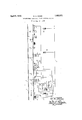
The accompanying drawing illustrates in a simplified and diagrammatic manner one specific embodiment of the invention applied to one signal location, the trackway signal being of the semaphore type, and the trackway impulse device ofthe inert element type.
To illustrate and explain the nature of the invention I have shown its application to one signal location on a double track railroad in which traflic normally moves in one direction, as indicated by the arrow. It should be understood, however, that the invention is applicable to single track railroads, equipped with a block signaling system of the type commonly known as an absolutepermissive-block type or the typical single track signaling system, as will be evident when the characteristic features of the invention are understood. The track rails 1 of the railroad track are divided by insulated joints 2 into track sections, one or more sections constituting the usual block, in accordance with common and recognized practice. Each of these track sections is provided with a track battery 3, or equivalent source of current, and a track relay T, providing the usual and well known normally closed track circuit.
While the invention is applicable to trackway signals of Various types, a semaphore signal Z of the three-position type has been shown conventionally; and as shown, the control circuits for this signal are of the well known typical form, using a home relay H and a distant relay D. The front contact 4 of the home relay H controls the usual 45 degree control circuit for the signal Z, which causes it to move from its horizontal or zero degree position to its inclined or 45 degree position to give a caution indication; and the front contact 5 of the distant relay D controls the usual degree control circuit to move the semaphore from its inclined or 45 degree to its vertical or 90 degree position and give the proceed or clear indication. To carry out this invention, the energizing circuits for the home and distant relays H and D differ from those commonly used in a particular manner which is more conveniently pointed out hereinafter in connection with the description of the operation.
The signal Z is provided with a circuit controller of the usual well known construction, which is shown in accordance with established convention. This circuit controller includes contacts 9, which are provided specially to carry out this invention and which are closed, as indicated by the conventional showing, only if the semaphore is in its vertical or proceed position.
When the invention is applied to a light signal, the function of these contacts 9 may be obtained by a front contact of the relay giving when energized the clear or proceed indication of the signal, or by the contacts of a relay connected in series with the filament of the lamp or lamps giving the clear indication, or otherwise associated with said filaments, so that said contacts are closed only if the signal is giving a clear indication. Such adaptations, being obvious to those skilled in the art are not illustrated.
Associated with the signal Z is the trackway impulse device TD of a train control system of a type which makes the application of this invention desirable. For the purpose of illustration, this trackway impulse device TD is assumed to be of the inert element type, comprising a coil 10 on a non-magnetized iron core 11, ordinarily U-shaped and provided with enlarged pole pieces. It is contemplated that this trackway impulse device TD will cooperate with a suitable car-carried receiver, together with brake control apparatus 0n the car, to produce an automatic brake application at each caution or stop signal, unless the engineer operates an acknowledging device. Such a system is disclosed, for example, in my prior Patent No. 1,604,098, dated October 19. 1926.
This track way impulse device TD is in its active stopping condition, and transmits an impulse to a passing train when its coil 10 is on open circuit. and is in itsinactive or non-stopping condition, when its coil 10 is included in a closed de-energized circuit of preferably low resistance or impedance. It should be understood that the circuit including the coil 10 of the trackway device TD must not only be closed, but must also be of relatively low resistance or impedance, in order that said trackway device may not influence the receiver on a passing train and produce a stopping impulse. It is therefore proposed in accordance with the present invention to provide means whereby before the wayside signal can be cleared the coil 10 must at least be intact to complete a circuit of rather high impedance and which impedance is too high to render the trackway device TD inactive, and whereby if the wayside signal is in proper working order and assumes the proceed or clear position through such ircuit of high impedance the impedance of this circuit including coil 10 is then reduced. In other words, it is proposed to prevent clearing of the wayside signal unless the coil 10 is intact and to prevent placing the coil 10 in a circuit of low resistance unless the wayside signal assumes the clear position.
In order to accomplish this end there is connected in multiple with the circuit con troller 9 current limiting device 12, which is so selected and proportionet that, when included in the closed circuit for the coil 10 of the trackway device TD, it will still render said trackway device active. This current limiting device 12 is preferably an impedance, usually including an iron core, having a coil thereon of relatively low ohmic resistance, although this, and other characteristics of the device 12, are'optional and susceptible of modification in practice.
O7)erati0n.Normally, under clear trailic conditions ahead, the home relay H is energized from a battery 31, or other source of current, in advance, over a line wire 13 including the front contacts 1% and 14 of the track relays T and T of the track sections constituting the block between the signal Z and the next signal in advance, wire 15, relay H, wire 16, contact finger 17 and its front contact of relay D, wires 18, 19 and 20 to the common return wire C and thence back to said source of current in advance. In practice, this line circuit for the relay H would also include any other controls governing the stopping condition of the signal Z, as for example, the front contact of the relay ll of the signal next in advance, in an A. P. B. system.
Under normal conditions, with the signal Z in its clear position and contacts 9 of its circuit controller closed, and the wires of the control circuit of the coil 10 of the trackway impulse device TD intact, there is a shunt or multiple path around the front contact 17 of the relay D, through which part of the energizing current for the home relay may flow. this shunt starting at the heel of the contact finger 17, being as follows: wire 21., contacts 9, wire 22, coil 10, wires 23 and 18. On account of the relatively high resistance of the coil 10 as compared with the resistance of contacts 17 and wire 18, a very small part Liu of the energizing current for the home relay H will normally flow through this shunt.
Under normal conditions, the distant relay D is energized from a battery 31, or other source of current, in advance, over a line circuit, including wire 24:, and controlling contacts 32 which govern the proceed or clear indication of the advance signal Z, the circuit proceeding through line Wire 24. through the finger and front contact 25 of the home relay H, wire 26, relay D, wire 27, finger 17 and front contact of relay D, wires 18, 19 and 20, to the common return wire C, and thence back to said battery- In one typical arrangement, which may be assumed for the purposes of this case, the line circuit for energizing the distant relay D or signal Z is taken through a circuit controller 32" 011 the signal next in advance closed when said signal next in advance is in its caution or proceed position.
Under the normal conditions described, coil 10 of the trackway impulse device TD is in eluded in a closed circuit of relatively low ohmic resistance as follows :commencing at the coil 10, Wire 22, contacts 9, wire 21, finger 17 and its front contact of relay D, and wire 18 and 23. The device TD is thus rendered inactive.
If, under ectain conditions, the signal Z should happen to assume its caution or stop position, even though there were no train in advance, on account of some defect, such as breaking of a control wire, then the contacts 9 of the circuit controller of the signal Z would open and include the current limiting device 12 in the circuit for the coil 10 of the device TD, thus rendering this device TD active to stop the train by reason of the fact t. at the choking effect of coil 10 has been substantially killed or subdued.
To bring out other characteristic features of the invention, assuming that a train passes the signal Z, let us consider the controlling condition of the trackway impulse device TD and the indication of the signal Z under various conditions, including defects in the control circun for said device TD, and in the signal operating mechanism.
When the train enters the track section J and de-energizes the track relay T, its finger 14cand front contact opens the energizing circuit for the home relay H; and the finger 25 and front contact of said home relay H in turn open the energizing circuit for the distant relay D, so that both of the relays H and D are de-energized. The de-energization of the relay D opens the control circuit for the coil 10 of the trackway device TD at the finger and front contact 17, so that said trackway device TD assumes its active stopping condition. It snould be noted that this will occur, even though the signal Z should,
, for any reason, remain in its clear position;
and in the event the signal does stick clear upon de-energization of relay D the controlling condition of the trackway device TD and the indication of the signal Z do not correspond. It is considered to be more important, however, to have the trackway device TD in the stopping condition, when the preschanically stuck in the clear position and it is obvious that an automatic brake application should occur in such rare instances, even though the engineer may be penalized for no fault of his own.
As the train advances out of the block protected by the signal Z, so that the contacts, such as the front contact 14 of the track relay T, included in the energizing circuit for the home relay H, are all closed, and the signal Z may properly assume its caution position,
so far as traflic conditions are concerned, said home relay H becomes energized, providing the control circuit for the coil 10 is intact. Since the distant relay D is de-energized, the energizing current for the relay H must pass over wire 21, through the current limiting device 12, wire 22, through the coil 10 and through wire 23. If, due to the passage of the train, or any other cause, the wires of the coil 10, or their connections, are broken, so that the trackway device D could not be placed in its inactive or non-stopping condition, then the home relay H cannot be energized, and the signal Z remains in the stop position. In other words, the integrity and continuity of the control circuit for the track device TD is checked each time the signal Z goes to stop; and if anything is wrong with this control circuit, this signal remains in the stop position. In this way, the indication of the signal Z is made to correspond with the controlling condition of the track device TD; and when this track device cannot assume its inactive condition, due to some defect, the indication of the signal warns the engineers of passing trains to acknowledge.
Even though the control circuit for the coil 10 of the trackway device TD is intact, and the home relay H may be energized to move the signal Z to the caution position, nevertheless said trackway device TD remains active, because the contacts 1'? are open and the cur rent limiting device 12 is included in its control circuit.
After the passing train has advanced to the point where the distant relay D may be properly energized to L llow the signal Z to assume its proceed or clear position (beyond the exit end of block K in the arrangement shown in the drawing), this relay D is energized, providing the control circuit for coil 10 is still intact, the energizing current for the relay D being obliged topass through the coil 10 and its control wires, the same as in the case of the home relay H. When the distant relay D is energized and its front contacts 17 closed, the track device TD assumes its inactive or non-stopping condition, providing the signal Z also moves to the 90 degree or proceed position and closes its contacts 9 to shunt the current limiting device 12. If the signal Z should for any reason fail to assume its clear position, the trackway device TD is maintained in its active stopping condition.
This feature, just described, which prevents the track device TD assuming the inactive condition unless the signal Z actually indicates proceed, is of particular advantage in the type of permissive system such as disclosed, for example, in the patentto Chas. S. Bushnell, No. 1,686,434 dated October 2, 1928, in which the engineer is given an indication in the cab, usually audible, whenever he op crates his acknowledging device, to tell him when he may properly restore the acknowledging device to normal. In this type of system, if the engineer maintains his acknowledging device in the operated position longer than a predetermined time, such as fifteen seconds, the brakes are automatically applied; and the audible signal is helpful to the engineer by advising him at the earliest moment when he may properly release his acknowledging device. Now, with such a system wherein the features of this invention are not present, if the signal should, due to the some defect, indicate caution, even though the track ahead were clear and the track device in its inactive or non-stopping condition, the engineer would acknowledge, but no impulse being transmitted by the inactive track device, the audible signal would not be given, and the engineer might hold down his acknowledging device so long as to get a brake application, while waiting for the audible signal to be given.
From the foregoing explanation, it can be seen that I have provided a means of control for the wayside block signal and track impulse transmitting device of an intermittent train control system, so as to obtain in a simple and direct way an efiective check on failure of either the signal or the trackway device to perform its intended function. In addition to the features already pointed out, it will be noted that, if the trackway device TD should happen to be torn out by a passing train, the associated signal Z would remain in the stop position. In this case, as well as in the others previously explained, all defects and failures at all likely to occur are on the side of safety; and in addition, the controlling condition of the trackway device TD is made dependent upon the existing indication of the signal Z, so far as consistent with safety, so that the engineer may not be misled by the indication of the signal Z and acknowledge, or fail to acknowledge, unless the track device TD is in corresponding condition.
Although I have shown and described in detail one specific embodiment of my invention, it should be understood that the specific means and circuit connections shown and described are susceptible of modification, without departing from the invention.
What I claim is 1. In a train control and wayside signaling system, a wayside signal, trackway impulse device for train control purposes having a control circuit, said trackway device assuming its active condition unless said control circuit is closed, contacts in said control circuit associated with the wayside signal and closed only if said signal indicates proceed, a relay controlled in accordance with traffic conditions ahead for independently governing said control circuit, and a circuit for re-energizing said relay after once de-energized including in part the wires of said control circuit.
2. In a train control and wayside signaling system, a wayside signal, a trackway impulse device for transmitting control influences inductively through an air gap to passing vehicles, said trackway device including a winding and assuming its active stopping condition unless a control circuit through said winding is closed, a relay controlled in accordance with traffic conditions ahead for governing the indication of the wayside signal, circuit controlling means associated with said signal and closed only if it indicates proceed, said control circuit for the trackway impulse device including a front contact of said relay and said circuit controlling means in series, and a stick circuit for said relay including said front contact, whereby upon deenergization of said relay, it cannot be again energized except by current flowing in part through the control circuit for the trackway impulse device.
3. In a train control and wayside signaling system, a wayside signal, contacts associated with said signal and closed only if it indicates proceed, a-trackway impulse device for transmitting control influences to passing vehicles, said trackway device comprising an inert magnetic core and a coil thereon and assuming its active stopping condition unless said coil is included in a closed circuit of low impedance, a relay governed in accordance with traflic conditions ahead, a stick circuit for said relay including a front contact thereof,
a control circuit for said coil of the trackway device including said contacts of the signal and said front contact of the relay and a current limiting device connected in multiple with said contacts of the signal.
4. In a Wayside signal and train control system, a trackway impulse device having a control circuit and assuming its active stopping condition unless said control circuit is closed and is of relatively low impedance, a relay governing said signal, means determining the energizati on of said relay depending upon the flow of the current through. the control circuit of the trackway impulse device regardless of whether the impedance of said control circuit is low or high, and means for automatically rendering the impedance of said control circuit relatively high unless the wayside signal indicates proceed.
5. In a train control system of thecharacter described, in combination with a trackway impulse device comprising a coil, said trackway device assuming its active impulse transmitting condition unless said coil is included in a closed circuit of relatively loW impedance, means for governing said control circuit in accordance with traffic conditions ahead, a wayside signal, and means associated with said signal for changing the impedance of said control circuit without interrupting its continuity dependent upon the indication of said signal.
6. In a train control system, the comb-ination with a wayside signal, of a train control track device, a control circuit of said device acting if closed to render said device inactive, means having its operation dependent upon the continuity of said control circuit for governing the indication of the wayside signal, and means associated with said signal and acting upon said control circuit without interrupting its continuity to cause said trackway device to assume its active stopping condition unless said wayside signal indicates proceed.
7. In a system of the character described, a train control trackway impulse device comprising an inert body of iron with a coil thereon, means governed in accordance with traffic conditions ahead for including said coil in a closed circuit of low impedance, a wayside signal, contacts associated with said signal and closed only if it indicates proceed, and an impedance connected in multiple with said contacts in said control circuit.
8. Trackway equipment for a combined trackway signaling and train control system comprising, a wayside signal, a trackway impulse device having a magnetic core and a coil thereon, a relay governed in accordance with traffic conditions ahead for controlling the indication of said signal, an energizing circuit for said relay including said coil of the trackway device and an impedance in series, whereby said relay when once de-energized can not be again energized unless said coil is intact, and contacts closed only if said signal indicates proceed and connected in multiple with said impedance.
9. A combined system of Wayside signaling and train control comprising, an impulse transmitting trackway element having an active and an inactive condition, a wayside signal, and automatic means for preventing said signal from giving a favorable indication, after having once been controlled to give a restrictive indication, unless said trackway device is capable of assuming its inactive condition, said means also preventing said track- Way device assuming such inactive condition uniessthe wayside signal gives its favorable indication.
l0. The combination with a trackway im-V favorable indication.
11. In an automatic wayside signal and train control system; the combination with a wayside signal; a traclrway train control device which includes a control circuit which must be intact to permit said device to be placed in its inactive non-stopping condition; a relay controlled in accordance with trailic conditions ahead; and means for causing said signal to indicate proceed if said trackway train control device has its control circuit intact and said relay manifests favorable traffic conditions ahead, and for causing said trackway train control device to assume its inactive non-stopping condition only if both said signal indicates proceed and said relay manifests favorable trafic conditions ahead.
12. In an automatic wayside signal and train control system, the combination with a wayside signal, a trackway train control device which includes a control circuit which must be intact to permit said device to be placed in its inactive non-stopping condition; a relay controlled in accordance with traffic conditions ahead, means requiring the integrity of said control circuit in order to function for causing said signal to assume the proceed condition in response to a favorable indicating condition of said relay, and means for placing said trackway device. in its inactive non-stopping condition only if both said signal and said relay indicate favorable traflic conditions.
13. The method of checking the proper functioning of a trackway influence communicating device which if active restricts the progress of the train of a'train control system by a proper wayside signal indication of a railway signaling system on which the train control system is superimposed and of checking the proper functioning of the wayside signal by placing the trackway device in a corresponding condition, which consists in first detecting whether or not the trackway device can be rendered inactive without actually rendering it inactive, then if said device is in condition to be rendered inactive allowing said wayside signal to clear providing traflic conditions ahead are clear, and then in rendering said trackway' device inactive in response to clearing of said wayside signal.
In testimony whereof I aifix my signature.
WINTHROP K. HOWE.
Priority Applications (1)
| Application Number | Priority Date | Filing Date | Title |
|---|---|---|---|
| US50685A US1852571A (en) | 1925-08-17 | 1925-08-17 | Intermittent inductive train control system |
Applications Claiming Priority (1)
| Application Number | Priority Date | Filing Date | Title |
|---|---|---|---|
| US50685A US1852571A (en) | 1925-08-17 | 1925-08-17 | Intermittent inductive train control system |
Publications (1)
| Publication Number | Publication Date |
|---|---|
| US1852571A true US1852571A (en) | 1932-04-05 |
Family
ID=21966757
Family Applications (1)
| Application Number | Title | Priority Date | Filing Date |
|---|---|---|---|
| US50685A Expired - Lifetime US1852571A (en) | 1925-08-17 | 1925-08-17 | Intermittent inductive train control system |
Country Status (1)
| Country | Link |
|---|---|
| US (1) | US1852571A (en) |
-
1925
- 1925-08-17 US US50685A patent/US1852571A/en not_active Expired - Lifetime
Similar Documents
| Publication | Publication Date | Title |
|---|---|---|
| US2391985A (en) | Railway signaling system | |
| US1852571A (en) | Intermittent inductive train control system | |
| US3025393A (en) | Highway crossing signal control system | |
| US2617921A (en) | Checking means for wayside train control inductors | |
| US2255192A (en) | Coded continuous train control and cab signaling system for railroads | |
| US2216713A (en) | Train control system | |
| US2275909A (en) | Trackway apparatus for automatic train control | |
| US1686434A (en) | Intermittent inductive train control | |
| US1730317A (en) | Permissive automatic train-control system | |
| US2233328A (en) | Intermittent inductive train control system | |
| US1605523A (en) | Automatic train-control system | |
| US1717338A (en) | Train control | |
| US1822497A (en) | Railway traffic controlling apparatus | |
| US1759404A (en) | Train control | |
| US1678615A (en) | Train control | |
| US1517231A (en) | Automatic train-control system | |
| US1316263A (en) | Train-control system | |
| CA2997854A1 (en) | Method for controlling a level crossing and railway installation for implementing such method | |
| US1492719A (en) | Railway-traffic-controlling apparatus | |
| US1794545A (en) | Continuous inductive train-control system | |
| US1717339A (en) | Train control | |
| US2045924A (en) | Continuous inductive train control system | |
| US1504075A (en) | Automatic train-control system | |
| US1664054A (en) | Block-signal system for railroads | |
| US1906021A (en) | Railway traffic controlling apparatus |