US1852564A - Clay gun - Google Patents
Clay gun Download PDFInfo
- Publication number
- US1852564A US1852564A US1852564DA US1852564A US 1852564 A US1852564 A US 1852564A US 1852564D A US1852564D A US 1852564DA US 1852564 A US1852564 A US 1852564A
- Authority
- US
- United States
- Prior art keywords
- cylinder
- piston
- clay
- platform
- rack bar
- Prior art date
- Legal status (The legal status is an assumption and is not a legal conclusion. Google has not performed a legal analysis and makes no representation as to the accuracy of the status listed.)
- Expired - Lifetime
Links
- 239000004927 clay Substances 0.000 title description 22
- 230000005540 biological transmission Effects 0.000 description 3
- 238000010079 rubber tapping Methods 0.000 description 3
- IATOMHNNMDOQEO-UHFFFAOYSA-N 2-(diethylamino)ethyl 2-phenylpentanoate;hydrochloride Chemical compound Cl.CCN(CC)CCOC(=O)C(CCC)C1=CC=CC=C1 IATOMHNNMDOQEO-UHFFFAOYSA-N 0.000 description 1
- 238000009825 accumulation Methods 0.000 description 1
- 239000010425 asbestos Substances 0.000 description 1
- 238000010276 construction Methods 0.000 description 1
- 239000000945 filler Substances 0.000 description 1
- 239000000463 material Substances 0.000 description 1
- 239000002184 metal Substances 0.000 description 1
- 230000004048 modification Effects 0.000 description 1
- 238000012986 modification Methods 0.000 description 1
- 229910052895 riebeckite Inorganic materials 0.000 description 1
- 239000002893 slag Substances 0.000 description 1
Images

Classifications
-
- C—CHEMISTRY; METALLURGY
- C21—METALLURGY OF IRON
- C21B—MANUFACTURE OF IRON OR STEEL
- C21B7/00—Blast furnaces
- C21B7/12—Opening or sealing the tap holes
Definitions
- This invention relates to mud or clay guns which are particularly applicable and useful forplugging up the tapping holes of blast furnaces to shut olf the iiow of molten metal 5 and slag therefrom.
- the invention isto provide a compact powerful gun capable of holding a large charge of clay, together with means for powerfully e'ecti the clay for the filling in one operal tion o the gun of a tapping hole to be plugged.
- An important object of the invention' is to. provide improved rack bar drive for the gun piston and a transmission driven by a coml paratively high speed motor to cause slow and owerful movement of the rack bar and shiftm of the piston through the cylinder to eject c a therefrom.
- Figure 2 is a section on plane II--II of Fi ure 1; a v
- igure 3 is an outer end view of the gun
- Fi re 4 is an enlarged section on plane IV- V of Fig. 1;
- Fi ure 5 is an enlarged section on plane V- of Figure 1.
- the structure disclosed comprises a cylinder having at its outer end the nozzle 11 and bein closed at its other end by a detachable ead 12.
- Reciprocable within the cylinder is a piston 13 and adjacent the nozzle end of the cylinder is the filling hole 14 for clay which hole may be securely closed by a suitable cover structure 15 and lock mecha-v nism 16.
- Adjacent to the other end ofthe t episton is fully retreated, there is another filler opening 17 which may also be provided with suitable closure structure (not shown);
- inwardly extending lug orl flange 24 on the head 12 forms a guide for the rack bar and the bar at its ends'has the reduced section or neck 25 which extends' through a hole 26 in :the piston 13, a nut 27 engaging the outer end of the neck to securely clam the piston to the bar so that the piston wil move with 'the bar as the bar is recprocated.
- the piston 13 has slots 33 and 34 which receive the guide bars so that the piston is supported concentrically-within the piston but independently of any engagement of its cylindrical surface with the cylinder wall in order to reduce friction and wear and tear of the surface due to the abrasive action of the clay.
- the piston may be of a diameter lslightly less than that of the cylinder bore and a washer of asbestos or other suitable material is preferably applied to the front of the piston and held in place by the nut 27. Besides accurately guiding the piston during its reciprocation in the cylinder, the bars 30 Vand 31 will prevent rotational movement of the piston and'will assist in keeping the rack bar in verticalalignment.
- the driving motor 36 whose shaft 37 is parallel with the axis of the cylinder, the shaft at its outer end carrying the pinion 38 which meshes with the large transmission gear 39 z securedto the outer end of the counter shaft 40 which extends parallel with the motor axis and is j ournalled in bearing structures 41 and 42 secured on the platform.
- the inner end of the counter shaft carries a spur pinion 43 meshing with the gear 44 on the shaft 45.
- This shaft 45 extends through the upper art -ofza housing structure formed by the alf ,46 preferably formed integral with the platform structure and the half 47 detachably applied to the half 46.
- the shaft 45 is journeynnlled in the opposite end walls formed by the housing structure and within the-housing be perfectintermes it carries a worn 48 which meshes with a worm wheel 49 secured on the outer end of a shaft 50 extending through the housing structure.
- the gear supportmg end of the shaft is journalled in the boss 51 on the outer housing half 47 and in the bearing lug 52 formed on the platform structure, the other end of the shaft being journalled in the bearing lug 53 depending from the platform.
- the shaft 50 supports a spur gear 54 which meshesl with'the teeth of the rack 22.
- the motor together with the gearing arrangement forms a very compa-ct and well balanced structure and with a comparatively high speed motor the rack willl be driven slowly and powerfully to shift' the piston through the cylinder for the rapid and-powerfull discharge of clay therefrom..l
- the gear rack applied with its teeth on the underside these -teeth will. be protected against accumulation of dirt and there will always f between the rack and the pinion 54.' i'
- the cylinder With the powerfu'lidrive' for the piston, the cylinder may be made .of large volume so that a'suiiicient chargeof clay may be received and ejected with one ls'trolre of the piston to fully and completely fill up a tapping hole. With two or more clay filling openings for the cylinder, the cylinder may be rapidly loaded. Where only a small quantity of clay is required, the piston need be retracted only a short distance and then clay filled in through the filling hole 14 adjacent to the nozzle end of the cylinder.
- a clay gun the combination of a cylinder, a discharge nozzle at one end of the cylinder, a head closing the other end of the cylinder, a platform extending from said head, said head having a guide opening below said platform, a rack bar below said platform in axial alignment with said cylinder and guided by said platform and through said guide opening, a piston in the cylinder secured toi the inner end of said rack bar to travel therewith, a motor mounted on said platform, a pinion engaging the rack bar, and a driving train between said'motor and said pinion for causing reciprocation of said rack bar and shift of said -piston in said cylinder., 'f
- a clay gun the combination of a cylinder having a nozzle at one end, a head closing the other end of said cylinder, a platform extending from said head, a rack bar below saidplatform, guide walls on said latform to guide said rack bar, said head aving a guide opening for said rack bar, a piston in the c linder secured to the inner -end' of said rac bar, the teeth on said rack bar being on the underside thereof, a pinion journalled below and meshing with said rack bar, a drivingv motor mounted on said platform, and a driving train between said motor and said pinion for causing slow and powerful reciprocation of said rack bar and movement of the piston in the cylinder for the ejection of clay therefrom.
- a clay" gun In a clay" gun, the combination of a ,cylinder having .a nozzle at one end, a head closing the other end of said cylinder, a iston gearing train between said motor and said rack bar for causing powerful reciprocation of said rack bar and of the piston, and supporting guides in said cylinder for saidvpiston for keeping the Weight of the piston off thebottom of the cylinder.
- a clay gun the combination of a cylinder havinga discharge nozzle at one end, a head closing the other end of said cylinder, a piston reciprocable in said cylinder, a platform supported by said head, a rack bar below the platform extending through said head and rigidly secured to the piston, a motor mounted on said platform with its axis ⁇ parallel with the cylinder axis, a countershaft journalled on said platform parallel with the motor axis, transmission gearing connecting said motor shaft and said counxtershaft, a cross shaft supported by said platforrm a pinion on said cross shaft meshing with said gear rack, a wormI wheel on said cross shaft, a worm engaging said worm wheel and having a supporting shaft, and a gearing train between said worm shaft and said countershaft, the gearing connection between' said motor and said rack bar causing 1 slow and powerful movement of said rack bar and movement of the piston in the cylinder.
- a clay gun having a discharge nozzle at one end, a head closing the other end of said cylinder, a piston reciprocable within said cylinder, a driving member secured to said piston and extendingtherefrom through said head, a driving motor, a driving connection between said motor and said driving member for causing slow and powerful movement of said piston in said cylinder whereby the cylinder may be of large volume vfor the ejection of a large quantity of clay, and a plurality of openings for the charging of clay into said cylinder.
- a clay gun the combination of a cylinder having a discharge nozzle at one end, a head closing the other end of the cylinder, a piston reciprocable in said cylinder, a driving member-secured tosaid piston' and extending therefrom through said head, a driving motor7 a reduction gearing train between said motor and said driving member for causing slow and powerful reciprocation of said pston, a clay filling hole for the cylinder adjacent the nozzle end thereof and another clay filling openingfor the cylinder adjacent to the head end thereof.
Landscapes
- Engineering & Computer Science (AREA)
- Chemical & Material Sciences (AREA)
- Manufacturing & Machinery (AREA)
- Materials Engineering (AREA)
- Metallurgy (AREA)
- Organic Chemistry (AREA)
- Reciprocating Pumps (AREA)
Description
April 5, 1932- A. F. GlEsE, JR 1,852,564
CLAY`GUN @filed March 26, 1931 2 sheets-sheet 1 i N N Il,
m? Img sg E- l o Q) w 'L :i
b `T H l u l: L ,l N Q I M x, t
| u) j l`l) K w t w ,E j l l I I V Y 0 il N s* I@ L zN w h j W Qzgasz 229.36, fn,
g.: Ml- LE..."
April 5, 1932-. A. F. GISE, JR
CLAY GUN Filedvmaroh 26,' 1931 2 sheets-sheet 2 Patented Apr. '5, 19324 Aucusr 11. amsn, :la or eau, nimma our GUN sppnomon mea :man se, 1931. serial no. 525,44.
This invention relates to mud or clay guns which are particularly applicable and useful forplugging up the tapping holes of blast furnaces to shut olf the iiow of molten metal 5 and slag therefrom. The general object of.
y the invention isto provide a compact powerful gun capable of holding a large charge of clay, together with means for powerfully e'ecti the clay for the filling in one operal tion o the gun of a tapping hole to be plugged.
An important object of the invention'is to. provide improved rack bar drive for the gun piston and a transmission driven by a coml paratively high speed motor to cause slow and owerful movement of the rack bar and shiftm of the piston through the cylinder to eject c a therefrom.
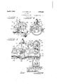
The a ove referred to and other features of the invention will become apparent from the following description in connection with the drawings, on which drawings Figure 1 is a plan view of the gun;
Figure 2 is a section on plane II--II of Fi ure 1; a v
Fi re 4 is an enlarged section on plane IV- V of Fig. 1;
The structure disclosed comprises a cylinder having at its outer end the nozzle 11 and bein closed at its other end by a detachable ead 12. Reciprocable Within the cylinder is a piston 13 and adjacent the nozzle end of the cylinder is the filling hole 14 for clay which hole may be securely closed by a suitable cover structure 15 and lock mecha-v nism 16. Adjacent to the other end ofthe t episton is fully retreated, there is another filler opening 17 which may also be provided with suitable closure structure (not shown);
Extending from the head 12 and referably formed integral therewith isa she f or platform 18 which is strengthened and reinforced by a number of webs or ribs 19. Depending from the platform along the medium lines thereof are the spaced apart parallel guide c linder and in advance of the piston whenv ribs or anges 20 and 21 which with the platform form a glxideway for a rack bar 22 whlch has teet 23 on its lower side. An
inwardly extending lug orl flange 24 on the head 12 forms a guide for the rack bar and the bar at its ends'has the reduced section or neck 25 which extends' through a hole 26 in :the piston 13, a nut 27 engaging the outer end of the neck to securely clam the piston to the bar so that the piston wil move with 'the bar as the bar is recprocated.
Within the cylinder at diametricall opposite sides thereof are the longitudinal y extending grooves 28 and 29 in which guide bars 30 and 31 are seated and secured in Yplace by means of bolts32. At its opposite lsides,the piston 13 has slots 33 and 34 which receive the guide bars so that the piston is supported concentrically-within the piston but independently of any engagement of its cylindrical surface with the cylinder wall in order to reduce friction and wear and tear of the surface due to the abrasive action of the clay. The piston may be of a diameter lslightly less than that of the cylinder bore and a washer of asbestos or other suitable material is preferably applied to the front of the piston and held in place by the nut 27. Besides accurately guiding the piston during its reciprocation in the cylinder, the bars 30 Vand 31 will prevent rotational movement of the piston and'will assist in keeping the rack bar in verticalalignment. p
Mounted on top of the platform 18 is the driving motor 36 whose shaft 37 is parallel with the axis of the cylinder, the shaft at its outer end carrying the pinion 38 which meshes with the large transmission gear 39 z securedto the outer end of the counter shaft 40 which extends parallel with the motor axis and is j ournalled in bearing structures 41 and 42 secured on the platform. y The inner end of the counter shaft carries a spur pinion 43 meshing with the gear 44 on the shaft 45. This shaft 45 extends through the upper art -ofza housing structure formed by the alf ,46 preferably formed integral with the platform structure and the half 47 detachably applied to the half 46. The shaft 45 isjournnlled in the opposite end walls formed by the housing structure and within the-housing be perfectintermes it carries a worn 48 which meshes with a worm wheel 49 secured on the outer end of a shaft 50 extending through the housing structure. The gear supportmg end of the shaft is journalled in the boss 51 on the outer housing half 47 and in the bearing lug 52 formed on the platform structure, the other end of the shaft being journalled in the bearing lug 53 depending from the platform. Between the bearing lugs 52 and 53 the shaft 50 supports a spur gear 54 which meshesl with'the teeth of the rack 22. l
The motor together with the gearing arrangement forms a very compa-ct and well balanced structure and with a comparatively high speed motor the rack willl be driven slowly and powerfully to shift' the piston through the cylinder for the rapid and-powerfull discharge of clay therefrom..l By having the gear rack applied with its teeth on the underside these -teeth will. be protected against accumulation of dirt and there will always f between the rack and the pinion 54.' i'
With the powerfu'lidrive' for the piston, the cylinder may be made .of large volume so that a'suiiicient chargeof clay may be received and ejected with one ls'trolre of the piston to fully and completely fill up a tapping hole. With two or more clay filling openings for the cylinder, the cylinder may be rapidly loaded. Where only a small quantity of clay is required, the piston need be retracted only a short distance and then clay filled in through the filling hole 14 adjacent to the nozzle end of the cylinder.
I have shown a practical and4 efficient embodiment of the various features of my invention but I do not desire to be limited to the construction and operation shown and described as changes and modifications may be made without departing from the scope of the invention as defined in the appended claims. t
I claim as follows:
1. In a clay gun, the combination of a cylinder, a discharge nozzle at one end of the cylinder, a head closing the other end of the cylinder, a platform extending from said head, said head having a guide opening below said platform,a rack bar below said platform in axial alignment with said cylinder and guided by said platform and through said guide opening, a piston in the cylinder secured toi the inner end of said rack bar to travel therewith, a motor mounted on said platform, a pinion engaging the rack bar, and a driving train between said'motor and said pinion for causing reciprocation of said rack bar and shift of said -piston in said cylinder., 'f
2. In. a clay gun, the combination of a cylinder having a nozzle at one end, a head closing the other end of said cylinder, a platform extending from said head, a rack bar below saidplatform, guide walls on said latform to guide said rack bar, said head aving a guide opening for said rack bar, a piston in the c linder secured to the inner -end' of said rac bar, the teeth on said rack bar being on the underside thereof, a pinion journalled below and meshing with said rack bar, a drivingv motor mounted on said platform, and a driving train between said motor and said pinion for causing slow and powerful reciprocation of said rack bar and movement of the piston in the cylinder for the ejection of clay therefrom. v. 3. In a clay" gun, the combination of a ,cylinder having .a nozzle at one end, a head closing the other end of said cylinder, a iston gearing train between said motor and said rack bar for causing powerful reciprocation of said rack bar and of the piston, and supporting guides in said cylinder for saidvpiston for keeping the Weight of the piston off thebottom of the cylinder. l
4. In a clay gun, the combination of a cylinder havinga discharge nozzle at one end, a head closing the other end of said cylinder, a piston reciprocable in said cylinder, a platform supported by said head, a rack bar below the platform extending through said head and rigidly secured to the piston, a motor mounted on said platform with its axis `parallel with the cylinder axis, a countershaft journalled on said platform parallel with the motor axis, transmission gearing connecting said motor shaft and said counxtershaft, a cross shaft supported by said platforrm a pinion on said cross shaft meshing with said gear rack, a wormI wheel on said cross shaft, a worm engaging said worm wheel and having a supporting shaft, and a gearing train between said worm shaft and said countershaft, the gearing connection between' said motor and said rack bar causing 1 slow and powerful movement of said rack bar and movement of the piston in the cylinder. i
5. In a clay gun, the combination of a. cylinder having a discharge nozzle at one end, a head closing the other end of said cylinder, a piston reciprocable within said cylinder, a driving member secured to said piston and extendingtherefrom through said head, a driving motor, a driving connection between said motor and said driving member for causing slow and powerful movement of said piston in said cylinder whereby the cylinder may be of large volume vfor the ejection of a large quantity of clay, and a plurality of openings for the charging of clay into said cylinder. y
6. In a clay gun, the combination of a cylinder having a discharge nozzle at one end, a head closing the other end of the cylinder, a piston reciprocable in said cylinder, a driving member-secured tosaid piston' and extending therefrom through said head, a driving motor7 a reduction gearing train between said motor and said driving member for causing slow and powerful reciprocation of said pston, a clay filling hole for the cylinder adjacent the nozzle end thereof and another clay filling openingfor the cylinder adjacent to the head end thereof.
In testimony whereof I have hereunto subscribed my name at Gary, Lake County,
Indiana.
AUGUST F. GIESE, JR.
Publications (1)
| Publication Number | Publication Date |
|---|---|
| US1852564A true US1852564A (en) | 1932-04-05 |
Family
ID=3423634
Family Applications (1)
| Application Number | Title | Priority Date | Filing Date |
|---|---|---|---|
| US1852564D Expired - Lifetime US1852564A (en) | Clay gun |
Country Status (1)
| Country | Link |
|---|---|
| US (1) | US1852564A (en) |
-
0
- US US1852564D patent/US1852564A/en not_active Expired - Lifetime
Similar Documents
| Publication | Publication Date | Title |
|---|---|---|
| US1908899A (en) | Vehicle for the collection of and the compressing of refuse and the like | |
| US1852564A (en) | Clay gun | |
| CN217227536U (en) | Tipping bucket type mine car convenient to dump based on coal mining | |
| US1852562A (en) | Clay gun | |
| CN220928005U (en) | Civil air defense engineering building backfill device | |
| US1852560A (en) | Hud gtjn | |
| CN216372715U (en) | Material distribution device | |
| US3483639A (en) | Drive group for the elevator of an elevator scraper | |
| US1783128A (en) | Cast iron | |
| CN214813384U (en) | Anti-adhesion stirring device for production of vehicle lubricating oil | |
| US1881478A (en) | f giese | |
| CN223560800U (en) | Ball storage chamber overload magnetic receiving and feeding structure in ball forging temperature control information system | |
| US2364513A (en) | Clay gun | |
| US1326789A (en) | schneider | |
| SU506549A1 (en) | Garbage truck | |
| US1881828A (en) | Car propeller for tunnel kilns | |
| US2941680A (en) | Travelling conveyer device, particularly for underground mining | |
| CN110482252B (en) | A stable and uniform feeding device for lubricating oil production | |
| CN214353321U (en) | Multifunctional self-feeding agitating lorry convenient for discharging | |
| US790332A (en) | Pot-filling apparatus for glass-furnaces. | |
| US2478055A (en) | Loading apparatus | |
| ES345314A1 (en) | Improvements in Vehicles for Collecting Refuse or the like | |
| US2101306A (en) | Mud gun | |
| CN220787062U (en) | Buried scraper conveyor with upper feeding tail part for unloading | |
| CN220391931U (en) | Conveying mechanism for processing asphalt |