US1852561A - giese - Google Patents
giese Download PDFInfo
- Publication number
- US1852561A US1852561A US1852561DA US1852561A US 1852561 A US1852561 A US 1852561A US 1852561D A US1852561D A US 1852561DA US 1852561 A US1852561 A US 1852561A
- Authority
- US
- United States
- Prior art keywords
- gun
- carriage
- motor
- furnace
- rollers
- Prior art date
- Legal status (The legal status is an assumption and is not a legal conclusion. Google has not performed a legal analysis and makes no representation as to the accuracy of the status listed.)
- Expired - Lifetime
Links
- 238000010079 rubber tapping Methods 0.000 description 27
- 238000007599 discharging Methods 0.000 description 15
- 239000004927 clay Substances 0.000 description 10
- 230000008878 coupling Effects 0.000 description 6
- 238000010168 coupling process Methods 0.000 description 6
- 238000005859 coupling reaction Methods 0.000 description 6
- XEEYBQQBJWHFJM-UHFFFAOYSA-N Iron Chemical compound [Fe] XEEYBQQBJWHFJM-UHFFFAOYSA-N 0.000 description 2
- 208000027418 Wounds and injury Diseases 0.000 description 2
- 230000006378 damage Effects 0.000 description 2
- 208000014674 injury Diseases 0.000 description 2
- 239000002184 metal Substances 0.000 description 2
- 229910052751 metal Inorganic materials 0.000 description 2
- 238000010276 construction Methods 0.000 description 1
- 230000000694 effects Effects 0.000 description 1
- 230000005611 electricity Effects 0.000 description 1
- 229910052742 iron Inorganic materials 0.000 description 1
- 230000004048 modification Effects 0.000 description 1
- 238000012986 modification Methods 0.000 description 1
- NJPPVKZQTLUDBO-UHFFFAOYSA-N novaluron Chemical group C1=C(Cl)C(OC(F)(F)C(OC(F)(F)F)F)=CC=C1NC(=O)NC(=O)C1=C(F)C=CC=C1F NJPPVKZQTLUDBO-UHFFFAOYSA-N 0.000 description 1
Images

Classifications
-
- C—CHEMISTRY; METALLURGY
- C21—METALLURGY OF IRON
- C21B—MANUFACTURE OF IRON OR STEEL
- C21B7/00—Blast furnaces
- C21B7/12—Opening or sealing the tap holes
-
- B—PERFORMING OPERATIONS; TRANSPORTING
- B22—CASTING; POWDER METALLURGY
- B22D—CASTING OF METALS; CASTING OF OTHER SUBSTANCES BY THE SAME PROCESSES OR DEVICES
- B22D41/00—Casting melt-holding vessels, e.g. ladles, tundishes, cups or the like
- B22D41/50—Pouring-nozzles
Definitions
- My invention relates to mud guns and particularly to an improved silpporting carriage therefor for carrying it bodily into position in front of 'a furnace, and improved means for positively and accurately guiding and moving the gun on the carriage into proper clay ejecting position relative to the furnace tapping hole.
- An important object of the invention 1s to provide a comparatively light, compact but rigid carriage structure providing runways or channels for receiving rollers on the mud gun to be controlled.
- Another important object is to arran e the runways or channels so that the gun wil normally be in horizontal position away from the furnace and above the runner trough, and when the gun is shifted towards the furnace, it will first be abruptly deflected downwardly at its front end to the proper angle for discharge and will then be moved in a straight line at such angle or inclination to enter the tapping hole, and so that when the gun is withdrawn, it will move in a straight line and will not break down the clay roof of the tapping hole.
- a further object is to rigidly support the front end of the gun carriage on the furnace wall so as to relieve the carriagesupport of considerable load while the gun 1s being shifted on the carriage into or out of dischargin position.
- Figure 1 is a side elevation of the gun, and gun carriage and support therefor, parts beingbroken away and the furnace being shown in section;
- Figure 2 is a plan view to a reduced scale
- Figure 3 is an enlarged view on plane III-III of Figure 1;
- Figure 4 is a side elevation showing a modified carriage arrangement and gun propulslon
- Figure 5 is an enlarged plan view of part of the gun carriage of Figure 4 and the gun propulsion means associated therewith.
- the mud gun may be of any of the wellknown and existing types driven by steam, electricity, or otherwise.
- the structure ma be like that disclosed in my copending application, Serial No. 435,435 filed March 2nd, 1930 orin, my copending application Serial No. 450,373, filed May 17th, 1930.
- a The gun is supported in a carriage structure C whichis suspended on a boom 20 at the outer end thereof, At its inner end the boom is securedto a vertical shaft or mast 21 which at its lower end is journalled for rotation in a bearing 22 supported on the floor 12, the shaft being held in upright position by suitable bracket. structures 23 secured to and extending from an adjacent fur nace column 24. At its upper end, the shaft carries a cable sheave 25 for a cable 26 extending from a sheave 27 driven by an electric motor 28 supportedat a distance away from the furnace. To properly reduce the speed, a suitable reduction gearing train 29 is interposed between the motor and the sheave 27 and preferably a slip coupling 30 is introduced between the motor and the gearing. Upon operation of the motor 28, the
- shaft 21 will be slowly rotated to swing the carriage and gun thereon away from or towards the furnace.
- the carriage structure C is' preferably of skeleton form to secure lightness and may be built up from metallic stock bars to secure strength and rigidity.
- the frame shown comprises the rear upper arms 31-31 of by braces 34 and secured at their inner ends to the boom 20. At their outer ends the arms 33 and 33' are secured to a front wall or'dash board 35 which may be of sheet metal.
- the opposite parallel channels 36-36 receive respectively the supporting elements 40 and 40' on opposite sides of the gun G; and as shown these elements may be in the form of rollers.
- the guideways 38 and 38 receive the supporting elements in the form of rollers 41 and 41 at the sides of the vertical wall 42 on the gun barrel. The gun structure is thus supported to roll on the carriage and the rollers may have ball'bearings in order to reduce frictional resistance.
- the guideways or channels 36-36 have the horizontal outer sections a and the downwardly and forwardly inclined sections 6.
- the inner ends 0 of the channels 3838' incline comparatively gradually downwardly and forwardly and may be parallel with the sections 6 of the channels 3636.
- the outer sections d of the channels 38-38 are shown as having the same inclination as the sections 0 and b and are therefore parallel therewith, andthe sections 0 and d are connected by. comparatively abruptly inclined sections 6 for quickly bringing the level of the rollers 41-41' from that of the sections (Z to that of the sections 6.
- the gun is in its outer position with the rollers 4040' at the outer ends of the channels 3636 and the rollers 41-41' at the outer ends of the upper inclined sections 0 of the channels 38 38', the gun being then preferably in horizontal alignment. "When the gun is swung with the carriage to be brought into position. above the runner trough l1 and the gun is then moved towards the furnace, the rollers 40-40 will travel in a horizontal line and the front rollers 41 -41" will travel through the inclined sections 0 so that the front end of the gun is given a slight inclination.
- a bracket structure 44 secured at its lower ends to the outer end of the gun structure extends upwardly and pivotally receives the oiiter end of a screw rod 45 which is held against rotation by its connection with the bracket structure 44.
- This screw rod passes through the threaded hub of a worm wheel 46 within a housing 47 which is mounted on a U-shaped cradle frame 48.
- a horizontal drive shaft 49 driven by a motor 50 and preferably including a slip coupling 49 extends through and is journalled in the housing 47 and carries a worm 51 meshing with the worm wheel 46.
- the worm wheel When the motor is operating the worm wheel will be rotated and, by its threaded engagement with the screw rod 45, this rod will be shifted axially to cause corresponding propulsion movement of the gun structure on the carriage C.
- the cradle frame 48 is trunnioned by means of pins 52 engaging in side brackets 53 secured on top of the boom 20.
- the gun may be powerfully propelled along the carriage to assume its desired position relative to the furnace and the tapping hole 10 thereof.
- it In operating the device, it is first swung to one side of the runner trough 11 (dotted lines in Figure 2) by means of the motor 28 and the cable 26.
- the extensions 54 from the front ends of the channel sections d form abutments for engaging on a ledge 55 on the furnace above the tapping hole so that the carriage will be supoverhang the tapping hole ledge -55 to assist the dash board in protecting'the gun and workmen from the flames and hot iron partiplels which may spurt out from the tapping
- the carriage structure is locked in its gundischarging position by means of a latch hook 57 engaging with a hooked latch lug 58 secured to the furnacewall. After a clay-discharging operation thelatch may be readily withdrawn from a remote point and then the motor is operated to bring the gun back to its normal horizontal position on the carriage, and then the motor 28 is operated to swing the carriage'back for receiving another charge. Before re-filling, the motor M is operated to draw back the gun piston or plunger.
- FIGS 4 and 5 I have shown a somewhat modified arrangement in which the supporting carriage framework is entirely above the gun so that the gun may be more readily accessible for charging or other purposes.
- the carriage comprises the side wall structures 59 and 59' secured to and depending from the boom 60 which, in this case, is secured to a vertical shaft 61 which is journalled in a pedestal structure .62 mounted on the floor 12.
- the shaft at its upper end has the sheave 25 rotated through a cable 26 by the operation of the motor 28 in a manner the same as that explained in connection with the struc ure of Figures 1 to 3.
- the walls 59 and 59' of the carriage structure have the downwardly and v and 59 have the inner downwardlv and forwardly inclined guide slots 67 and the outer less inclined slots 68, these slots receiving the rollers 69 at the ends of the shaft 70 supported in brackets v71 extending upwardly axially in a straight line to project its nozzle into the tapping hole 10 of the furnace,
- An extension 72 from the carriage structure supports a latching or coupling member 7 3 for engaging a companion coupling member 74 on the furnace, so that the carriage will be locked when the gun is being propelled thereon to its discharging position.
- screw rod 75 engages the front roller shaft 70 of the carriage and extends rearwardly through a threaded sleeve 77 journalled within a housing 7-8 between the carriage guide walls 59 and 59'.
- an electric motor 80 On a shelf or platform 79 supported from the boom 60 is an electric motor 80 whose shaft 81 extends'into the housing 78 where it supports a pinion 82 which meshes with a gear 83 secured to the threaded sleeve 77.
- a hearing structure 84 on the guide wall 59 journals the outer end of the motor shaft, and between this bearing and the pinion 82 the adjacent end of the housing 78 is j ournalled on to rotate relative to the shaft.
- the opposite end of the housing 78 has a trunnion pin 85 extending therefrom into a bearing 86 on the guide wall 59 so that the housing may rotate to follow the variations in angularity of the screw shaft 75 as the gun is propelled along the carriage structure by the axial movement of the screw red by the rotation of the sleeve 77.
- a slip coupling 87 is preferably interposed between the motor 80 and the pinion 82 to prevent injury to the parts in case the motor 15 not stopped when the gun supporting rollers reach the ends of their guide slots.
- I thus produce a light, compact. but strong carriage structure affording positive guiding means for rollers on .the gun structure. so, that the gun structure may be quickly moved in the shortest time from it's horizontal position down to its final movement in a straight line .into the tapping hole, or in a straight line out of the tapping hole to prevent breaking down of the clay roof of the tapping passage defined by the gun nozzle.
- the various movements of the carriage and of the gun supported thereon are performed powerfully, positively and safely, and injury to the various parts is prevented by the slip couplings introduced in the motor driving trains.
- the combination with aimridgun having front and rear; supporting elements at its sides, of a supporting ca rriagetherefor having front and rear guideways for receiving said supportingelements, said elements normally engaging in the outer ends of said guideways to support said gun'insubstantially horizontal position, said front guideways having intermediate abruptly downwardly inclined sections which when engaged by said front supporting elements will cause quick downward swing of said gun into discharging alignment, and said front and rear guideways having end sections which when engaged by said supporting elements will cause said gun to be shifted axially in a straight line into discharging position.
- a mud gun having front and rear supporting rollers on opposite sides thereof, of a supporting carriage for the gun having front and rear guide channels at its sides for said front and rear rollers respectively, said front guidechannels being deflected to cause first abrupt downward swing of the gun into inclined position and then axial shift of the gun while thus inclined to bring it into discharging position.
- Apparatus for closing furnace tapping holes comprising a vertical shaft, a boom extending from said shaft to swing horizontallywhen said shaft is turned, a-carriage supportedfrorn said boom, a mud gun shiftable on said carriage, means for turning said shaft to swing the boom to bring the carriage into operating position, a motor mounted on said boom, and a driving connection between said motor and said gun for controlling the shifting of said gun on said carriage into or out of discharging position.
- Apparatus for closing furnace tapping holes comprising asupport adapted to swing horizontally, a carriage suspended from said support, a clay gun shiftable on said carriage, means for swinging. said support to bring the carriageand gun into operating position, a motor supported by said carriage support, a screw rod extending from said gun, and a driving connection between said motor and screw rod for controlling the shifting of said gun on said carriage into or out of clay discharging position.
- Apparatus for closing furnace tapping holes comprising a vertical shaft, a beam secured to and extending laterally from said shaft to swing horizontally when said shaft is rotated, a carriage suspended from said beam, a mud gun shiftable on said carriage, means controllable from a distance for rotating said shaft to cause said beam to swing said carriage into operating position, a motor supported by said beam, a screw rod extending from said gun, a driving train between said motor and said screw rod for controlling the shifting of said gun on said carriage into or out of discharging position, said driving train including a worm driven by said motor and a worm wheel receiving said screw rod.
- a supporting structure and means for moving it bodily toward a furnace tapping hole, said supporting structure having guideways, a mud gun suspended from said guideway to be shifted thereon, and means carried wholly b said supporting structure for shifting sai gun, said guideways being directioned to guide said gun when shifted for a discharge oper-' ation to cause it first to be deflected downwardly to bring its discharge end into position in front of the tapping hole and then to causeit to move axially in a straight line to bring its discharging end into discharging position in said hole.
- Apparatus for closing furnace tapping holes comprising a supporting structure, a
- clay gun structure shiftable on said supporting structure, a'motor supported on one of said structures, a screw rod extending from the other structure, and a driving connec-' tion between said motor and screw rod for controlling the shifting of said gun structure on said supporting structure into or out of clay discharging position.
- a furnace having a tapping hole, of a supporting carriage, a mud gun shiftable on said carriage, a support for said carriage operable to move said carriage bodily into or out of operating position relative to said furnace, a supporting ledge on said furnace directly above said tapping hole, and a projection on said carriage for engaging said abutment when said carriage is moved to operating position whereby said carriage will be held a ainst depression when said gun is shifted thereon into discharging position.
Landscapes
- Engineering & Computer Science (AREA)
- Mechanical Engineering (AREA)
- Chemical & Material Sciences (AREA)
- Manufacturing & Machinery (AREA)
- Materials Engineering (AREA)
- Metallurgy (AREA)
- Organic Chemistry (AREA)
- Spray Control Apparatus (AREA)
Description
April 5, 1932. @555, J'R 1,852,561
MUD GUN CARR IAGE F'iled Dec. '11, 1930 4 Sheets-Sheet 1- April 5, 1932. -A. F. GIESE, JR
MUD GUN CARRIAGE 4 Sheets-Sheet 2 Filed Dec. 11,' 1930 LmvEm/EP April 1932- A. F. GIESE, JR 1,852,561
\ MUD GUN CARRIAGE Fil ed Dec. 11, 1950 4 Sheets-Sheet a April 5, 1932. v A. F. GIEVSE, JR 1,852,561
' MUD GUN CARRIAGE Filed Dec. 11. 1930 4 Sheets-Sheet 4 vmummml iiiiiiiiim Jagyusili 65658 V2 Patented' Apr. 5,1932
- UNITED STATES PATENT OFFICE AUGUST I. GIESE, 33., GARY, INDIANA 1 IUD GUN CARRIAGE Application filed December 11, 1980. Serial No. 501,498. I
My invention relates to mud guns and particularly to an improved silpporting carriage therefor for carrying it bodily into position in front of 'a furnace, and improved means for positively and accurately guiding and moving the gun on the carriage into proper clay ejecting position relative to the furnace tapping hole. a
An important object of the invention 1s to provide a comparatively light, compact but rigid carriage structure providing runways or channels for receiving rollers on the mud gun to be controlled.
Another important object is to arran e the runways or channels so that the gun wil normally be in horizontal position away from the furnace and above the runner trough, and when the gun is shifted towards the furnace, it will first be abruptly deflected downwardly at its front end to the proper angle for discharge and will then be moved in a straight line at such angle or inclination to enter the tapping hole, and so that when the gun is withdrawn, it will move in a straight line and will not break down the clay roof of the tapping hole.
A further object is to rigidly support the front end of the gun carriage on the furnace wall so as to relieve the carriagesupport of considerable load while the gun 1s being shifted on the carriage into or out of dischargin position.
The a ove specified and other features of my invention are incorporated in the. structure disclosed on the drawings, in which drawings:
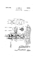
Figure 1 is a side elevation of the gun, and gun carriage and support therefor, parts beingbroken away and the furnace being shown in section;
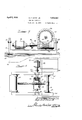
Figure 2 is a plan view to a reduced scale;
Figure 3 is an enlarged view on plane III-III of Figure 1;
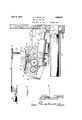
Figure 4 is a side elevation showing a modified carriage arrangement and gun propulslon;
Figure 5 is an enlarged plan view of part of the gun carriage of Figure 4 and the gun propulsion means associated therewith.
I have shown the gun structure associated filling ho per 15. A piston 16 with "a furnace F having the usiial tapping hole 10 in. front of which extends the runner trough 11 for receiving the discharge molten metal, the tapping hole and the running trough being below the level of a supporting floor 12 on which the gun carriage structure is mounted and o erated.
The mud gun may be of any of the wellknown and existing types driven by steam, electricity, or otherwise. The structure ma be like that disclosed in my copending application, Serial No. 435,435 filed March 2nd, 1930 orin, my copending application Serial No. 450,373, filed May 17th, 1930. Briefly, the gun structure as shown in Fig. 1 com- 811588 the barrel or cylinder 13 having the ischarge nozzle 14 and rovided vwith a clay I within the cylinder as a gear rack 16 extending ou wardly therefrom throu h the cylinder head 17, and a gear 18 driven by a motor M isconnected through reduction gearing 19 with the gear rack or screw shaft 16.
a The gun is supported in a carriage structure C whichis suspended on a boom 20 at the outer end thereof, At its inner end the boom is securedto a vertical shaft or mast 21 which at its lower end is journalled for rotation in a bearing 22 supported on the floor 12, the shaft being held in upright position by suitable bracket. structures 23 secured to and extending from an adjacent fur nace column 24. At its upper end, the shaft carries a cable sheave 25 for a cable 26 extending from a sheave 27 driven by an electric motor 28 supportedat a distance away from the furnace. To properly reduce the speed, a suitable reduction gearing train 29 is interposed between the motor and the sheave 27 and preferably a slip coupling 30 is introduced between the motor and the gearing. Upon operation of the motor 28, the
The carriage structure C is' preferably of skeleton form to secure lightness and may be built up from metallic stock bars to secure strength and rigidity. The frame shown comprises the rear upper arms 31-31 of by braces 34 and secured at their inner ends to the boom 20. At their outer ends the arms 33 and 33' are secured to a front wall or'dash board 35 which may be of sheet metal.
Below the arms 31 and 31' are the guideways or channels 36 and 36 secured at their outer ends to the frame section 32 and at their inner ends being supported by hanger bars 37 secured to the arms 3131. Below the arms 33-33 are the opposite and parallel guideways or channels 38 and 38 which are secured at their outer ends to the dashboard 35 and at their nner ends are secured .to vertical or hanger bars 39 extending downwardly from the arms 33'33.
The opposite parallel channels 36-36 receive respectively the supporting elements 40 and 40' on opposite sides of the gun G; and as shown these elements may be in the form of rollers. The guideways 38 and 38 receive the supporting elements in the form of rollers 41 and 41 at the sides of the vertical wall 42 on the gun barrel. The gun structure is thus supported to roll on the carriage and the rollers may have ball'bearings in order to reduce frictional resistance.
The guideways or channels 36-36 have the horizontal outer sections a and the downwardly and forwardly inclined sections 6.
- The inner ends 0 of the channels 3838' incline comparatively gradually downwardly and forwardly and may be parallel with the sections 6 of the channels 3636. The outer sections d of the channels 38-38 are shown as having the same inclination as the sections 0 and b and are therefore parallel therewith, andthe sections 0 and d are connected by. comparatively abruptly inclined sections 6 for quickly bringing the level of the rollers 41-41' from that of the sections (Z to that of the sections 6.
Normally, the gun is in its outer position with the rollers 4040' at the outer ends of the channels 3636 and the rollers 41-41' at the outer ends of the upper inclined sections 0 of the channels 38 38', the gun being then preferably in horizontal alignment. "When the gun is swung with the carriage to be brought into position. above the runner trough l1 and the gun is then moved towards the furnace, the rollers 40-40 will travel in a horizontal line and the front rollers 41 -41" will travel through the inclined sections 0 so that the front end of the gun is given a slight inclination. When the rollers 4141 reach the abrupt inclined sections e the gun is rapidly tilted down to project its nozzle into the trough 11, the gun during these movements swinging around the axis of the outer rollers 4040. When the front rollers 4141 enter the inclined outer channel sections (1 the rollers 4040 will enter the inclined sections 12 and then the gun will move axially in a straight line to project its nozzle into the tapping hole 10. When the gun is withdrawn it wlll first travel axially in a straight line to withdraw its nozzle from the tapping hole and as the rollers travel along the sections, 6, 0, and a, the gun will be swung upwardly into its normal horizontal' outer position. To strengthen the guideways or channels and-make them more rigid, the ends of the sections 6 and the adjacent ends of the sections d may be connected by brace members 43 which may also be secured to the lower ends of the hanger bars 39.
Referring to Figures 1 and 3, I have shown an efficient means for propelling the gun on the carriage to move it into or out of claydischarging position. A bracket structure 44 secured at its lower ends to the outer end of the gun structure extends upwardly and pivotally receives the oiiter end of a screw rod 45 which is held against rotation by its connection with the bracket structure 44. This screw rod passes through the threaded hub of a worm wheel 46 within a housing 47 which is mounted on a U-shaped cradle frame 48. A horizontal drive shaft 49 driven by a motor 50 and preferably including a slip coupling 49 extends through and is journalled in the housing 47 and carries a worm 51 meshing with the worm wheel 46. When the motor is operating the worm wheel will be rotated and, by its threaded engagement with the screw rod 45, this rod will be shifted axially to cause corresponding propulsion movement of the gun structure on the carriage C. To permit the rod 45 to assume various angles in vertical direction as the gun is propelled, the cradle frame 48 is trunnioned by means of pins 52 engaging in side brackets 53 secured on top of the boom 20. Thus, when the motor is operated, the gun may be powerfully propelled along the carriage to assume its desired position relative to the furnace and the tapping hole 10 thereof. In operating the device, it is first swung to one side of the runner trough 11 (dotted lines in Figure 2) by means of the motor 28 and the cable 26. In this position, the gun barrel .is filled with clay and then the motor 28 is again operated to swing the carriage to bring the gun into position above the trough 11 as shown in full line in Figures 1 and 2. The motor 50 is now operated to propel the gun forwardly to bring its nozzle into the tapping hole 10, and then the motor M is operated to shift the piston through the gun barrel to effect discharge of the clay from the gun nozzle into the tapping hole. It will be noted that the extensions 54 from the front ends of the channel sections d form abutments for engaging on a ledge 55 on the furnace above the tapping hole so that the carriage will be supoverhang the tapping hole ledge -55 to assist the dash board in protecting'the gun and workmen from the flames and hot iron partiplels which may spurt out from the tapping The carriage structure is locked in its gundischarging position by means of a latch hook 57 engaging with a hooked latch lug 58 secured to the furnacewall. After a clay-discharging operation thelatch may be readily withdrawn from a remote point and then the motor is operated to bring the gun back to its normal horizontal position on the carriage, and then the motor 28 is operated to swing the carriage'back for receiving another charge. Before re-filling, the motor M is operated to draw back the gun piston or plunger.
In Figures 4 and 5, I have shown a somewhat modified arrangement in which the supporting carriage framework is entirely above the gun so that the gun may be more readily accessible for charging or other purposes. The carriage comprises the side wall structures 59 and 59' secured to and depending from the boom 60 which, in this case, is secured to a vertical shaft 61 which is journalled in a pedestal structure .62 mounted on the floor 12. The shaft at its upper end has the sheave 25 rotated through a cable 26 by the operation of the motor 28 in a manner the same as that explained in connection with the struc ure of Figures 1 to 3. At their outer ends the walls 59 and 59' of the carriage structure have the downwardly and v and 59 have the inner downwardlv and forwardly inclined guide slots 67 and the outer less inclined slots 68, these slots receiving the rollers 69 at the ends of the shaft 70 supported in brackets v71 extending upwardly axially in a straight line to project its nozzle into the tapping hole 10 of the furnace,
substantially all in the same manner as with the arrangement of Figures 1 to 3. An extension 72 from the carriage structure supports a latching or coupling member 7 3 for engaging a companion coupling member 74 on the furnace, so that the carriage will be locked when the gun is being propelled thereon to its discharging position.
In the arrangement of Figures 4 and 5 a.
screw rod 75 engages the front roller shaft 70 of the carriage and extends rearwardly through a threaded sleeve 77 journalled within a housing 7-8 between the carriage guide walls 59 and 59'. On a shelf or platform 79 supported from the boom 60 is an electric motor 80 whose shaft 81 extends'into the housing 78 where it supports a pinion 82 which meshes with a gear 83 secured to the threaded sleeve 77. A hearing structure 84 on the guide wall 59 journals the outer end of the motor shaft, and between this bearing and the pinion 82 the adjacent end of the housing 78 is j ournalled on to rotate relative to the shaft. The opposite end of the housing 78 has a trunnion pin 85 extending therefrom into a bearing 86 on the guide wall 59 so that the housing may rotate to follow the variations in angularity of the screw shaft 75 as the gun is propelled along the carriage structure by the axial movement of the screw red by the rotation of the sleeve 77.
A slip coupling 87 is preferably interposed between the motor 80 and the pinion 82 to prevent injury to the parts in case the motor 15 not stopped when the gun supporting rollers reach the ends of their guide slots.
I thus produce a light, compact. but strong carriage structure affording positive guiding means for rollers on .the gun structure. so, that the gun structure may be quickly moved in the shortest time from it's horizontal position down to its final movement in a straight line .into the tapping hole, or in a straight line out of the tapping hole to prevent breaking down of the clay roof of the tapping passage defined by the gun nozzle. The various movements of the carriage and of the gun supported thereon are performed powerfully, positively and safely, and injury to the various parts is prevented by the slip couplings introduced in the motor driving trains.
Although I have shown practical and eflicient embodiments of the various features of my invention, I do not desire to be limited to the details shown, as modifications and changes may be made in the construction,
arrangement, and operation without departing from the scope and spirit of the invention as outlined in the appended claims.
I claim as follows:
1. The combination with a mud gun having front and rear supporting elements, of asupporting carriage therefor having guidewardly and then to shift the gun axially in a straight line into discharging position.
,2. The combination-with a mud gun having front and rear guide rollers at its sides, of a carriage havmg guideways for receiving said rollers, said guideways being'directioned to guide said gun for abrupt'downward swing and then for axial shiftjgalong a straight line into discharging. position. v
3. The combination with aimridgun having front and rear; supporting elements at its sides, of a supporting ca rriagetherefor having front and rear guideways for receiving said supportingelements, said elements normally engaging in the outer ends of said guideways to support said gun'insubstantially horizontal position, said front guideways having intermediate abruptly downwardly inclined sections which when engaged by said front supporting elements will cause quick downward swing of said gun into discharging alignment, and said front and rear guideways having end sections which when engaged by said supporting elements will cause said gun to be shifted axially in a straight line into discharging position.
4. The combination with a mud gun having front and rear supporting rollers at its opposite sides, of a supporting carriage for the gun having guideways forsaid respective rollers, said guideways being aligned to normally support the gun in a normal upper position, and said guideways being deflected to cause first abrupt downward swing of said gun into inclined position' and then axial shift of the gun while in such inclined position to bring it into discharging position.
5. The combinationwith a mud gun having front and rear supporting rollers on opposite sides thereof, of a supporting carriage for the gun having front and rear guide channels at its sides for said front and rear rollers respectively, said front guidechannels being deflected to cause first abrupt downward swing of the gun into inclined position and then axial shift of the gun while thus inclined to bring it into discharging position.
6. In apparatus for closing furnace tapping holes, the combination of a vertical rotatable shaft, a boom extending from said shaft to swing horizontally when said shaft is turned, a carriage suspended from said boom, a mud gun shiftable on said carriage, means controllable from a distance for rotating said shaft to swing said boom to carry said carriage into operative position relative to the furnace, and means mounted on said boom for controlling the shifting of said gun on said carriage into or out of dischargcarriage suspended from said boom, a mud gun shiftable on said carriage, and means mounted on said boomand connected with s 8. Apparatus for closing furnace tapping holes comprising a vertical shaft, a boom extending from said shaft to swing horizontallywhen said shaft is turned, a-carriage supportedfrorn said boom, a mud gun shiftable on said carriage, means for turning said shaft to swing the boom to bring the carriage into operating position, a motor mounted on said boom, and a driving connection between said motor and said gun for controlling the shifting of said gun on said carriage into or out of discharging position.
9. Apparatus for closing furnace tapping holes comprising asupport adapted to swing horizontally, a carriage suspended from said support, a clay gun shiftable on said carriage, means for swinging. said support to bring the carriageand gun into operating position, a motor supported by said carriage support, a screw rod extending from said gun, and a driving connection between said motor and screw rod for controlling the shifting of said gun on said carriage into or out of clay discharging position.
10. Apparatus for closing furnace tapping holes comprising a vertical shaft, a beam secured to and extending laterally from said shaft to swing horizontally when said shaft is rotated, a carriage suspended from said beam, a mud gun shiftable on said carriage, means controllable from a distance for rotating said shaft to cause said beam to swing said carriage into operating position, a motor supported by said beam, a screw rod extending from said gun, a driving train between said motor and said screw rod for controlling the shifting of said gun on said carriage into or out of discharging position, said driving train including a worm driven by said motor and a worm wheel receiving said screw rod.
11. The combination with a furnace havindependently of said locking means when said carriage is in operating position.
12. In apparatus for closing a furnace tapping hole, the combination of a supporting structure and means for moving it bodily toward a furnace tapping hole, said supporting structure having guideways, a mud gun suspended from said guideway to be shifted thereon, and means carried wholly b said supporting structure for shifting sai gun, said guideways being directioned to guide said gun when shifted for a discharge oper-' ation to cause it first to be deflected downwardly to bring its discharge end into position in front of the tapping hole and then to causeit to move axially in a straight line to bring its discharging end into discharging position in said hole.
13. Apparatus for closing furnace tapping holes comprising a supporting structure, a
clay gun structure shiftable on said supporting structure, a'motor supported on one of said structures, a screw rod extending from the other structure, and a driving connec-' tion between said motor and screw rod for controlling the shifting of said gun structure on said supporting structure into or out of clay discharging position. 14. The combination with a furnace having a tapping hole, of a supporting carriage, a mud gun shiftable on said carriage, a support for said carriage operable to move said carriage bodily into or out of operating position relative to said furnace, a supporting ledge on said furnace directly above said tapping hole, and a projection on said carriage for engaging said abutment when said carriage is moved to operating position whereby said carriage will be held a ainst depression when said gun is shifted thereon into discharging position.
In testimony whereof I have hereunto subscribed my name at Gary, Lake County,
Indiana. 7
AUGUST F. GIESE, JR.
Publications (1)
| Publication Number | Publication Date |
|---|---|
| US1852561A true US1852561A (en) | 1932-04-05 |
Family
ID=3423631
Family Applications (1)
| Application Number | Title | Priority Date | Filing Date |
|---|---|---|---|
| US1852561D Expired - Lifetime US1852561A (en) | giese |
Country Status (1)
| Country | Link |
|---|---|
| US (1) | US1852561A (en) |
Cited By (1)
| Publication number | Priority date | Publication date | Assignee | Title |
|---|---|---|---|---|
| US2747858A (en) * | 1956-05-29 | miller |
-
0
- US US1852561D patent/US1852561A/en not_active Expired - Lifetime
Cited By (1)
| Publication number | Priority date | Publication date | Assignee | Title |
|---|---|---|---|---|
| US2747858A (en) * | 1956-05-29 | miller |
Similar Documents
| Publication | Publication Date | Title |
|---|---|---|
| US1431857A (en) | Loading machine | |
| US2174956A (en) | Dumping truck | |
| US2836309A (en) | Scrap car | |
| US1397324A (en) | Earth-boring machine | |
| US1852561A (en) | giese | |
| US2259966A (en) | Fire extinguishing apparatus | |
| US2423167A (en) | Scaffold | |
| US3279628A (en) | Furnace charger | |
| CN111059897B (en) | Automatic melting system | |
| US1726069A (en) | Mtjd-gun cabbiage | |
| US1783128A (en) | Cast iron | |
| RU196233U1 (en) | FIRE ENGINE | |
| CN109913630A (en) | Axle tube quenching device | |
| US1266828A (en) | Conveying mechanism. | |
| US1726070A (en) | Mud gun | |
| US1450702A (en) | Wheel-pit drop table | |
| US1481211A (en) | Mechanical shovel | |
| US1189680A (en) | Airship. | |
| US1881478A (en) | f giese | |
| US1810654A (en) | Support especially for heavy machine guns or the like | |
| US1753731A (en) | Industrial truck | |
| US898501A (en) | Wagon-loading device. | |
| US1384768A (en) | Bevolvin | |
| CN206049566U (en) | A kind of wheel protection structure of forklift for slag | |
| US2543956A (en) | Container-handling machine for pouring from one container into another |