US185255A - Improvement in coal-hoisting apparatus - Google Patents
Improvement in coal-hoisting apparatus Download PDFInfo
- Publication number
- US185255A US185255A US185255DA US185255A US 185255 A US185255 A US 185255A US 185255D A US185255D A US 185255DA US 185255 A US185255 A US 185255A
- Authority
- US
- United States
- Prior art keywords
- hoisting
- coal
- lever
- rope
- bucket
- Prior art date
- Legal status (The legal status is an assumption and is not a legal conclusion. Google has not performed a legal analysis and makes no representation as to the accuracy of the status listed.)
- Expired - Lifetime
Links
- 239000003245 coal Substances 0.000 description 7
- 241000283086 Equidae Species 0.000 description 4
- 241000239290 Araneae Species 0.000 description 1
- 229910001018 Cast iron Inorganic materials 0.000 description 1
- 239000011449 brick Substances 0.000 description 1
- 230000000717 retained effect Effects 0.000 description 1
Images
Classifications
-
- B—PERFORMING OPERATIONS; TRANSPORTING
- B66—HOISTING; LIFTING; HAULING
- B66C—CRANES; LOAD-ENGAGING ELEMENTS OR DEVICES FOR CRANES, CAPSTANS, WINCHES, OR TACKLES
- B66C21/00—Cable cranes, i.e. comprising hoisting devices running on aerial cable-ways
Definitions
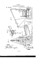
- Figure 1 represents a side elevation, partly in section, of my improved apparatus for hoisting coal and other articles.
- Fig. 2 is a sectional end view of the same, and Fig. 3 a detail sectional side view of the bucketconveying carrier.
- the object of my invention is to furnish an improved apparatus for the purpose of hoisting coal, bricks, and other articles from vessels or other places directly into the carts or other vehicles, by utilizing the power of the horse or horses pulling the same for hoisting the coal, &c., in economical manner, so as to obtain the direct transfer of the articles, and dispense with a special horse, steam-engine, or other power for hoisting.
- the invention consists of an inclined endless belt, with step-shaped parts, to be operated by the cart-horse for rotating a drum, on which the hoisting-rope is wound.
- the cord runs over guide-pulleys of a supporting-frame and of a bucket-conveying carriage, that locks and unlocks a fixed button in automatic manner to convey the load or lower bucket.
- the work of the endless stepping-belt is stopped or interrupted by a lever actuating a double clutch and brake mechanism of the windingdrum shaft.
- a weighted lever and swinging hub-locking standard secures the cart or vehicle in stationary position for hoisting action of horse.
- A represents an endless belt, that is stretched over toothed spider frame-wheels B, which engage intermeshing projections of step-shaped parts a, connected by suitable pivot-links.
- the steps a are preferably made of sustaining or stiffening frames, of cast-iron, and wooden facings, so arranged that the horses find a good foot-hold thereon.
- the endless stepping-belt is arranged at such inclination on the wharf or other place where the hoisting apparatus is to be used that part of the belt is below and part of the same above the level of the wharf.
- the steps a are also arranged at a small angle of inclination to the supporting-chains, for the purpose of providing, as near as possible, a horizontal support or rest for the feet of the horses.
- the cart or other vehicle is guided by rails bearing at the inside of the wheels to the belt, the horse or horses stepping on the same, being then in position to work the same.
- the vehicle is locked into rigid position on the wharf before the horse begins to work the belt by means of a standard, 0, at one or both sides of the guide-track, the standard being provided with a recess, I), for fitting over and binding on the hub of the vehicle.
- the standard G is hinged at the lower part to the wharf, and operated by a crank-rod, d, and lever d with weighted handle d so as to be readily released from the hub.
- a curved guide-piece, e, at the upper part of the standard U, sidewise of the hub-recess b, serves to throw the standard 0 sufficiently back by the hub that the vehicle may pass on and be locked automatically by the standard and the weighted levers 01 d
- the winding-drum D is thrown into or out of gear with its shaft by the double clutch f.
- the clutch f is operated by a fulcrumed lever, f, that engages, by its lower semicircular end, the grooved slidingclutch, being set, by its upper handle end, into a notched lock-bar, f for the purpose of securing the clutch to the winding-drum, or applying a brake, f connected to the lever f and acting on a fixed pulley of the drum, or for throwing the clutch entirely out of gear with the drum for admitting the unwinding of the hoisting-rope.
- the lever is applied to the second notch of the lock-bar, the rotation of the drum and of the endless belt is interrupted, and the load of the hoistingrope retained at the required point.
- the hoisting-rope E passes over pulleys of a stationary or movable frame, F, secured to the wharf, and arranged to project beyond the same, so that the bucket applied to the end of the hoisting-rope may readily be lowered into the boat or other vessel.
- the hoistingrope E passes also over a pulley of a carrier,
- the carrier F is provided with two V-shaped pivot-levers, g 1 of which one has a hook-shaped upper arm, while the other lever has a hook at the lower arm, its upper arm being weighted.
- the pivoted lever 9 looks the carrier F, by its hook end, to a pointed or tapering stop-plate, 1 at the lower end of the inclined way, while the second lever, g hears, with its upper weighted part, on the inclined stop-plate 9 so as to raise the lower hook end clear of the pulley.
- a conical button, h at the required distance above the bucket, which button strikes against the lower ends of both pivot-levers, producing first the locking of the longer hook-arm of the weighted lever g over the base of the button, and then' the raising of the other lever by contact with the shorter lower arm of the same, as shown in detail in Fig. 3, so as to produce the unlocking of the carrier and the traveling of the same, with the bucket suspended therefrom, along the inclined way of the supporting-frame E.
- the button It may be adjusted at any suitable point on the rope, as it is made of two detachable parts-a conical shank and the disk-shaped base-which are screwed together.
- the button By unscrewing the parts and sliding the shank along the hoisting-rope, and forn1- ing a knot between shank and base, and finally connecting the parts, the button may be rigidly affixed at any part of the rope.
- the carrier When the bucket arrives at the point above the cart the carrier is locked by the clutch and the bucket emptied. The clutch is then released entirely. from the winding-drum, and the carrier and bucket thereby allowed to descend on the inclined way till the lever-hooks form contact with the stop plate, so as to release the button and lower the bucket into the vessel.
- the cart-horse is thus used, while being harnessed to the cart, for hoisting the load into the cart, dispensing with extra power, the cart or vehicle being released from the hub-standard when loaded, and the horse allowed to pass over the belt and an inclined plane at the end of the belt directly to any point of storage, forming thus a convenient and economical means of hoisting and conveying coal and other articles from vessels.
- a swingin g standard operated by weighted lever, and having recess to lock to hub of vehicle, for utilizing power of horse on stepping-belt, substantially as specified.
Landscapes
- Engineering & Computer Science (AREA)
- Mechanical Engineering (AREA)
- Load-Engaging Elements For Cranes (AREA)
Description
e. PACI.
I COAL'HOISTING APPARATUS.
WITNESSES monnns.
THE GRAPHIC C04 N-Y Ua'rran STATES Ra'rma'r @rrroa,
GUISEPPE PACI, OF NEW YORK, N. Y.
IMPROVEMENT IN COAL-HOISTING APPARATUS.
Specification forming part of Letters Patent No. 185,255, dated December 12, 1876; application filed October 7, 1876.
To all whom it may concern:
Be it known that I, GUIsEPPE PAOI, of the city, county, and State of New York, have invented a new and Improved Apparatus for Hoisting Goal, of which the following is a specification In the accompanying drawing, Figure 1 represents a side elevation, partly in section, of my improved apparatus for hoisting coal and other articles. Fig. 2 is a sectional end view of the same, and Fig. 3 a detail sectional side view of the bucketconveying carrier.
Similar letters of reference indicate correspondin g parts.
The object of my invention is to furnish an improved apparatus for the purpose of hoisting coal, bricks, and other articles from vessels or other places directly into the carts or other vehicles, by utilizing the power of the horse or horses pulling the same for hoisting the coal, &c., in economical manner, so as to obtain the direct transfer of the articles, and dispense with a special horse, steam-engine, or other power for hoisting.
The invention consists of an inclined endless belt, with step-shaped parts, to be operated by the cart-horse for rotating a drum, on which the hoisting-rope is wound. The cord runs over guide-pulleys of a supporting-frame and of a bucket-conveying carriage, that locks and unlocks a fixed button in automatic manner to convey the load or lower bucket. The work of the endless stepping-belt is stopped or interrupted by a lever actuating a double clutch and brake mechanism of the windingdrum shaft. A weighted lever and swinging hub-locking standard secures the cart or vehicle in stationary position for hoisting action of horse.
In the drawing, A represents an endless belt, that is stretched over toothed spider frame-wheels B, which engage intermeshing projections of step-shaped parts a, connected by suitable pivot-links. The steps a are preferably made of sustaining or stiffening frames, of cast-iron, and wooden facings, so arranged that the horses find a good foot-hold thereon. The endless stepping-belt is arranged at such inclination on the wharf or other place where the hoisting apparatus is to be used that part of the belt is below and part of the same above the level of the wharf. The steps a arealso arranged at a small angle of inclination to the supporting-chains, for the purpose of providing, as near as possible, a horizontal support or rest for the feet of the horses. The cart or other vehicle is guided by rails bearing at the inside of the wheels to the belt, the horse or horses stepping on the same, being then in position to work the same. The vehicle is locked into rigid position on the wharf before the horse begins to work the belt by means of a standard, 0, at one or both sides of the guide-track, the standard being provided with a recess, I), for fitting over and binding on the hub of the vehicle. The standard G is hinged at the lower part to the wharf, and operated by a crank-rod, d, and lever d with weighted handle d so as to be readily released from the hub. A curved guide-piece, e, at the upper part of the standard U, sidewise of the hub-recess b, serves to throw the standard 0 sufficiently back by the hub that the vehicle may pass on and be locked automatically by the standard and the weighted levers 01 d On the shaft of the stretching-wheels B, below the level of the wharf, is placed loosely a winding-drum, 1), for the hoisting-rope E. The winding-drum D is thrown into or out of gear with its shaft by the double clutch f. The clutch f is operated by a fulcrumed lever, f, that engages, by its lower semicircular end, the grooved slidingclutch, being set, by its upper handle end, into a notched lock-bar, f for the purpose of securing the clutch to the winding-drum, or applying a brake, f connected to the lever f and acting on a fixed pulley of the drum, or for throwing the clutch entirely out of gear with the drum for admitting the unwinding of the hoisting-rope. When the lever is applied to the second notch of the lock-bar, the rotation of the drum and of the endless belt is interrupted, and the load of the hoistingrope retained at the required point. The hoisting-rope E passes over pulleys of a stationary or movable frame, F, secured to the wharf, and arranged to project beyond the same, so that the bucket applied to the end of the hoisting-rope may readily be lowered into the boat or other vessel. The hoistingrope E passes also over a pulley of a carrier,
F, that moves on inclined ways of frame F,
and serves to convey the bucket along the inclined way. The carrier F is provided with two V-shaped pivot-levers, g 1 of which one has a hook-shaped upper arm, while the other lever has a hook at the lower arm, its upper arm being weighted. The pivoted lever 9 looks the carrier F, by its hook end, to a pointed or tapering stop-plate, 1 at the lower end of the inclined way, while the second lever, g hears, with its upper weighted part, on the inclined stop-plate 9 so as to raise the lower hook end clear of the pulley. To the hoisting-rope E is attached a conical button, h, at the required distance above the bucket, which button strikes against the lower ends of both pivot-levers, producing first the locking of the longer hook-arm of the weighted lever g over the base of the button, and then' the raising of the other lever by contact with the shorter lower arm of the same, as shown in detail in Fig. 3, so as to produce the unlocking of the carrier and the traveling of the same, with the bucket suspended therefrom, along the inclined way of the supporting-frame E. The button It may be adjusted at any suitable point on the rope, as it is made of two detachable parts-a conical shank and the disk-shaped base-which are screwed together. By unscrewing the parts and sliding the shank along the hoisting-rope, and forn1- ing a knot between shank and base, and finally connecting the parts, the button may be rigidly affixed at any part of the rope. When the bucket arrives at the point above the cart the carrier is locked by the clutch and the bucket emptied. The clutch is then released entirely. from the winding-drum, and the carrier and bucket thereby allowed to descend on the inclined way till the lever-hooks form contact with the stop plate, so as to release the button and lower the bucket into the vessel.
The cart-horse is thus used, while being harnessed to the cart, for hoisting the load into the cart, dispensing with extra power, the cart or vehicle being released from the hub-standard when loaded, and the horse allowed to pass over the belt and an inclined plane at the end of the belt directly to any point of storage, forming thus a convenient and economical means of hoisting and conveying coal and other articles from vessels.
Having thus described my invention, I claim as new and desire to secure by Letters Patent-- 1. An improved apparatus for hoisting coal and other articles from the vessels, consisting of an inclined endless stepping-belt with winding-drum, hoisting-rope, and bucket-conveying carrier, and supportingdtame, substantially in the manner and for the purpose specified.
2. In an apparatus for hoisting coal, a swingin g standard, operated by weighted lever, and having recess to lock to hub of vehicle, for utilizing power of horse on stepping-belt, substantially as specified.
3. The swinging-and hub-locking standard 0, having curved guide-piece e to lock automatically to hub, substantially as set forth.
4. The combination of hoisting-rope E, having fixed button It, carrier F, having pivoted and weighted lever-hooks g g and stop-plate g of frame A, to release or look carrier from stop-plate of frame F, substantially as specifled.
GUISEPPE PAOI.
Witnesses:
PAUL GoEPEL, U. SEDGWIGK.
Publications (1)
| Publication Number | Publication Date |
|---|---|
| US185255A true US185255A (en) | 1876-12-12 |
Family
ID=2254660
Family Applications (1)
| Application Number | Title | Priority Date | Filing Date |
|---|---|---|---|
| US185255D Expired - Lifetime US185255A (en) | Improvement in coal-hoisting apparatus |
Country Status (1)
| Country | Link |
|---|---|
| US (1) | US185255A (en) |
-
0
- US US185255D patent/US185255A/en not_active Expired - Lifetime
Similar Documents
| Publication | Publication Date | Title |
|---|---|---|
| US185255A (en) | Improvement in coal-hoisting apparatus | |
| US317083A (en) | bradford | |
| US784586A (en) | Hoisting device. | |
| US315934A (en) | Horse-power for hay-carriers | |
| US91819A (en) | Peters | |
| US501658A (en) | Automatic elevator-lock | |
| US507767A (en) | Elevated carrier | |
| US184848A (en) | Improvement in elevating and-carrying machines | |
| US1283932A (en) | Excavating apparatus. | |
| US393285A (en) | Water elevator and carrier | |
| US714306A (en) | Elevated hay-carrier. | |
| US638722A (en) | Apparatus for elevating, transporting, and discharging material. | |
| US489785A (en) | Frank | |
| US636902A (en) | Apparatus for elevating, transporting, and discharging material. | |
| US292098A (en) | Hay-carrier | |
| US430073A (en) | Gravity-hoist | |
| US832392A (en) | Loading apparatus. | |
| US559852A (en) | Apparatus for elevating | |
| US52001A (en) | Vania | |
| US170301A (en) | Improvement in cranes | |
| US196910A (en) | Improvement in hay elevator and carrier | |
| US273462A (en) | capen | |
| US185986A (en) | Improvement in boat-launching apparatus | |
| US244874A (en) | Grain dumping and elevating device | |
| US420516A (en) | Jean baptiste nadeau |