US1852556A - Leer feeder - Google Patents
Leer feeder Download PDFInfo
- Publication number
- US1852556A US1852556A US281952A US28195228A US1852556A US 1852556 A US1852556 A US 1852556A US 281952 A US281952 A US 281952A US 28195228 A US28195228 A US 28195228A US 1852556 A US1852556 A US 1852556A
- Authority
- US
- United States
- Prior art keywords
- ware
- belt
- conveyor
- leer
- carriage
- Prior art date
- Legal status (The legal status is an assumption and is not a legal conclusion. Google has not performed a legal analysis and makes no representation as to the accuracy of the status listed.)
- Expired - Lifetime
Links
Images
Classifications
-
- C—CHEMISTRY; METALLURGY
- C03—GLASS; MINERAL OR SLAG WOOL
- C03B—MANUFACTURE, SHAPING, OR SUPPLEMENTARY PROCESSES
- C03B35/00—Transporting of glass products during their manufacture, e.g. hot glass lenses, prisms
- C03B35/04—Transporting of hot hollow or semi-hollow glass products
- C03B35/06—Feeding of hot hollow glass products into annealing or heating kilns
- C03B35/08—Feeding of hot hollow glass products into annealing or heating kilns using rotary means directly acting on the products
- C03B35/085—Transfer mechanisms of the "endless-chain" type
Definitions
- the present invention relates to improvements in leer feeders and particularly to automati'c-m'eans for placing ware, such asbot+ tles, jars or other articles, in an-upright po-' sition on a leer conveyor which carries the Ware through an annealing chamber for tempering.
- ware such asbot+ tles, jars or other articles
- An object of the invention is "to provide improved means for removing ware from a belt and guiding a ware pusher belt in a fashion to impart a sliding movement of the ware transversely. of the length of theh'ot belt.
- This pusher belt is sufficiently flexible to yield slightly under excessive pressure of ware coming in contact therewith and is of a texture to prevent scratching the surface of the ware as is frequently experienced ,with certain other types of feeders.
- Another object is to provide a ware pusher of the above character which is capable of adjustment to accurately control the speed at which ware is removed from the cross conveyor or hot belt.
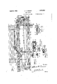
- Fig. 1 is a lan view illustrating one form of the inventlon.
- F i 2 is a sectional view along the line 11- Iof Fig.1.
- Fig. '2'A is a detail view o'f one end of the screw shaft. 7
- Fig. 2-B is a cross sectional view of the the detent or swivel nut enga 'ng the t reads.
- i 3 isa-sectional v'iew taken along the line IIIII of Fig. 1.
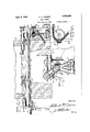
- I 7 Fig. 4 is a fragmentary front elevation.
- Fig. 5 is an end elevation.
- ,Fi 5A isa detail view showing the drive for t 0 hot belt.
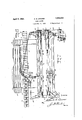
- Fig. 6 is a plan view of another form of the invention.
- the leer feeder is illustrated in'conjunction with a glassware annealing leer of conventional type, including side walls 10 between which is arranged a leer conveyor 11 for car-" rying ware'through'an annealing chamber
- Fig. is a fragmentary front elevation of 12 locatedjbetween said side walls.
- This leer conveyor 11 may be of any preferred construction and moved either continuously or intermittently to carry the ware through "the leer.
- Theside walls 10 (Figflfareformed,
- Automatic means to remove ware from the hot belt 14 includes an endless pusher belt 15 set on edge and running lengthwise of the hot belt 14 in a plane sli htly above the upper surface of the latter. he pusher belt 15 is trained over pulleys 16 and is of such length that portions maybe extended across said hot belt and function as a ware pushing device, as will be apparent presently. Y
- a shaft 23 extends parallel with the ware conveyor-'or'hot belt 14 in advance of the latter and' is formed with double spiral threads. 24 comprising part-of a mechanism for moving-the'pusher' belt transversely rela-v tive tojthe direction of travel of said ware conveyor. These threads 24 Fig. 2A) are connected at each end by a s ort circumferential thread 24 which permits reversal of the direction of movement of a carriage 33 hereinafter described.
- This shaft 23 has its ends journalled in bearings 25 at the upper ends of the standards 19.
- a sprocket 26 is fixed to one end of this shaft and is connected to-another sprocket 27 by a chain 28.
- the second sprocket 27 is secured to a shaft 29 journalled in a bearing 29 on one of the standards 19 and carries a bevel gear 30 at its inner end running in mesh with a gear 30 on the vertical shaft 17.
- the means for imparting continuous movement to the pusher belt 15 also functions to rotate the screw shaft 23.
- the hot belt 14 is driven by a sprocket 80 running in mesh with the chain 81 connecting the elements making up the belt 14.
- This sprocket 80 is mounted upon a shaft 82 which carries a bevel gear 83 running in mesh with the aforementioned bevel gear 30,
- Means to position a portion of-the pusher belt 15 across the ware conveyor 14 to move ware fromthe latter to the leer conveyor 11, includes a pair of rollers 31 arranged above the hot belt 14 for engagement with opposite faces of said pusher belt 15. These rollers 31 (Fig. 1) are positioned adjacent opposite side edges of thehot belt 14 and at points spaced from each other longitudinally of said hot belt. The relative positions of the rollers 31 predetermines the angular relation between the ware pushing portion 32 of the pusher belt 15-and the Ware conveyor 14. Feeding of different sized ware into the leer or changing the speed of delivery of ware to the leer may require adjustment of the ware pushing portion 32 to change its angular relation to the line of movement of the hot belt 14. Ac-.
- rollers 31 are mounted upon a carriage 33 constructed to permit various changes in the relative positions of said rollers.
- This carriage 33 comprises a bracket 34 formed with a collar 35 through which the shaft 23 extends.
- the collar 35 carries a detent 36 or swivel nut which engages said double spiral threads 24 upon the shaft 23 one at a time, so that rotation of the shaft causes the carriage 33 to travel back and forth in a direction lengthwise of the shaft.
- the detent or swivel nut 36 is yieldingly held in engagement with the threads by a spring 36.
- This detent which moves with the carriage 33 travels through the short thread 24 (F'g; 2-A) from one thread to the other to reverse the direction of travel of the carriage, it being understood that the shaft is continuously rotating.
- the bracket 34 (Figs. 1 and 2) is formed with arigid arm 37 at its outer end, said arm extending laterally in ahorizontal plane from the bracket 34 and carrying a depending stub shaft 38' uponv which one of the rollers 31 is j ournalled.
- An arm 39 is pivoted'to a hinge in 40 rising from the outer end of the brac et 34 and carries at its outer end a depending stub shaft 41 upon which the second roller 31 is journalled.
- This latter arm 39 is formed with an arcuate plate 42 in-which a series of vertical openin s 43 is formed, said openings being adapted orregister one at atime with an opening 44 in the outer portion of the bracket 34.
- a removable screw 45 operates to secure the arm 39 in any adjusted relation to the other arm 37 and thereby insures retention of the ware pushing portion 32 of the pusher belt 15 at any redetermined angle relative to' the line of tra el of the ware conveyor 14.
- the roller supporting carriage 33 is held in proper spaced relation above the hot belt 14 by providing the collar 35 with a depending arm 46 which carries a roller 47 at its lower end.
- This roller runs in a guideway 48 formed between a pair of bars 49 or rails which extend parallel with the shaft 23. Due to the rigid connection between the depending arm 46 and the bracket 34 (Fi 2), the bars 49 or rails operate to prevent ownward tilting of the roller supporting carriage 33 beyond the desired point.
- the pusher belt 15 is held taut by a belt tightener (Figs. 1 and 3) comprising a base portion 50 secured to the upper side of the guide rails 49 at one end ofthe latter and supporting a slide block 51 having a roller carrying arm 52 thereon.
- a roller 53 on said arm 52 constantly contacts with the adjacent outer face of the pusher belt 15.
- An adjusting screw 56 is operable to regulate the tension of the sprin 54.
- ware In operating the feeder ]l1St described, ware is continuously delivered to areas within the feeding end of the leer by the ware conveyor 14 substantially as shown in Fig. 1.
- the screw shaft 23 is rotated continuously and thereby imparts reciprocatory movement to the carriage 33 and parts carried thereby to projectthe ware pushing portion 32 of the'belt 15 across the path of travel of ware on the hot belt 14.
- the conveyor 14 travels continuously from left to right (Fig. 1).
- the carriage 33 is reciprocated lengthwise of the shaft 23.
- the carriage preferably travels at the same speed as the conveyor 14 so that while the carriage is moving to the right there is no relative movement between it and the conveyor.
- row of bottles which have been placed on the 'wiping action is assisted by conveyor at regular intervals, as shown, is carried into the leer.
- the carriage 33 reaches the limit of its movementwit-h the conveyor, its direction of movement is reversed so that the ware engaging portion 32 of the belt 15 Wipes the bottles off the conveyor 14 onto the leer conveyor 11.
- This the angular position of thepart '32 of the belt and is also materially assisted by the movement of the belt in the direction of its length.
- the speed at which the belt rotates is preferably such as to reduce the frictional resistance between the belt and the bottles to a minimum, thereby minimizing the friction or rubbing action of the belt on the bottles, so that scratchin or injury to the ware is avoided.
- the lielt being made of or faced with comparatively soft flexible materiahi such as an asbestos composition, the liability of'scratching or marring the surface of the ware is practically eliminated.
- the leer conveyor 11 is advanced so that the next succeeding row of bottles will be suitably spaced from the preceding row.
- the pusher belt-15 is set. on edge, as in the precedingform, but has its ends secured to holders at the upper ends of standards .61 located adjacent the opposed openings 13 in the leer walls 10.
- a coil spring 62 (Fig. .6) interposed tensions the belt so that the ware pushing portion 32 lying between the rollers 31 on the eciprocating carriage 33, is properly positioned to remove ware from the conveyor 14.
- the threaded shaft 23 carries a sprocket 64 at one end, said sprocket having driving connection throu'gha chain 65 or the like with a sprocket .66, the latter fixed to a shaft. 67 upon which a bevel gear 68 is mounted. This gear runs in mesh with a driving bevel gear 69 at the upper end of a shaft 70 which may be rotated by any suitable means (not shown).
- the carriage 33 is reciprocated along the screw shaft 23, whereby the rollers on said carriage impart 'to' the-ware pushing f portion 32 of the belt 15 a movement'substantially in the direction of the travel of ware through the leer.
- the ware pushing portions of the pusher belt 15 constantly/ shift across the Width of the leer to thereby eflect deposit of ware in rows extending transversely of the length of the leer;
- a leer feeder comprising in combination, a conveyor, means to .move the conveyor whereby the latter may carry ware along a predetermined path, a flexible member extending lengthwise of and in part alongside the conveyor, a device to move portions of said member transversely of the path of travel of the ware with the cfzflveyor, for removing the ware from the la, ter, and means to reciprocate the device lengthwise of said path.
- a leer feeder comprising in combination,
- A-leer feeder comprising in combination, a conveyor, means to move the conveyor whereby the latter may carry articles along a predetermined path, a carriage adapted for reciprocationin parallelism to the path of travel of the conveyor, rollers on said carriage, said rollers positioned adjacent opp0-. site edges of the ware conveyor and at points spaced apart lengthwise of the conveyor, an article pusher belt set on edge and extending said belt engaging the i across the leer, said belt en aging the rollers whereby a ortion thereof 1s deflected across the path 0 travel of the conveyor to remove articles from the latter, means for reci rocating the carriage, and. meansfor changing the spaced relation between said rollers and thereby varying the angular relation between the a conveyor and the article engaging portion of the pusher belt.
Description
Ap 5, 1932. A. N. CRAMER L555 FEEDER Fild May 51. 1928 3 Sheets-Sheet l Apfil 5,1932.
A. N. CRAMER LEER FEEDER Filed May 31, 1928 3 Sheets-Sheet 3 Patented Apr. 5, 1.932
UNITED STATES PATENT oFncE ALBERT it. cause, or TOLEDO, onro, ASSIGNOB- To owns-rumors eLAss con- PANY, or TOLEDO, OHIO, Av conrom'rron or onto LEER Application men May.31, 1928. Serial no. 28 1352.
1 The present invention relates to improvements in leer feeders and particularly to automati'c-m'eans for placing ware, such asbot+ tles, jars or other articles, in an-upright po-' sition on a leer conveyor which carries the Ware through an annealing chamber for tempering. TI L I An object of the invention is "to provide improved means for removing ware from a belt and guiding a ware pusher belt in a fashion to impart a sliding movement of the ware transversely. of the length of theh'ot belt. This pusher belt is sufficiently flexible to yield slightly under excessive pressure of ware coming in contact therewith and is of a texture to prevent scratching the surface of the ware as is frequently experienced ,with certain other types of feeders.
Another object is to provide a ware pusher of the above character which is capable of adjustment to accurately control the speed at which ware is removed from the cross conveyor or hot belt.-
.- shaft showin In the accompanying drawings: Fig. 1 is a lan view illustrating one form of the inventlon. F i 2 is a sectional view along the line 11- Iof Fig.1. Fig. '2'A is a detail view o'f one end of the screw shaft. 7
Fig. 2-B is a cross sectional view of the the detent or swivel nut enga 'ng the t reads.
Fig. 5 is an end elevation. ,Fi 5Aisa detail view showing the drive for t 0 hot belt.
Fig. 6 is a plan view of another form of the invention.
the same.
In the drawings, Figs. 1 to 5 A, inclusive, the leer feeder is illustrated in'conjunction with a glassware annealing leer of conventional type, including side walls 10 between which is arranged a leer conveyor 11 for car-" rying ware'through'an annealing chamber Fig. is a fragmentary front elevation of 12 locatedjbetween said side walls. This leer conveyor 11 may be of any preferred construction and moved either continuously or intermittently to carry the ware through "the leer. Theside walls 10 (Figflfareformed,
with opposed openings 13 through which a continuously moving ware conveyor or hotbelt 14 extends for conveying ware trans; versely of the direction of travel of the leer conveyor '11 to "areas within the leer.
Automatic means (Figs. 1 and 2) to remove ware from the hot belt 14 includes an endless pusher belt 15 set on edge and running lengthwise of the hot belt 14 in a plane sli htly above the upper surface of the latter. he pusher belt 15 is trained over pulleys 16 and is of such length that portions maybe extended across said hot belt and function as a ware pushing device, as will be apparent presently. Y
These pulleys 16 (Figs. 1 and 4) over which the pusher belt 15 runs, are positioned adjay cent the front edge of the Ware conveyor 14 Other objects will be apparent hereinafter.
or hot belt in proximity to, the opposed openings 13 in. the side walls of the leer. Vertical shafts 17 carry said pulleys and are journalled in bearings 18 at the upper ends ofstandards 19. One of these shafts 17 (at the "right side of the leer; iii the present disclosure), extends considerably below its bearing 1-8 and is connected through a gear and worm mechanism 20 to'the shaft 21 on a motor '22. This motor 22 operates to continuously'move the pusher belt 15 over the supportin pulleys 16 whereby ware may be remove from the conveyor 14 as will be described.
A shaft 23 extends parallel with the ware conveyor-'or'hot belt 14 in advance of the latter and' is formed with double spiral threads. 24 comprising part-of a mechanism for moving-the'pusher' belt transversely rela-v tive tojthe direction of travel of said ware conveyor. These threads 24 Fig. 2A) are connected at each end by a s ort circumferential thread 24 which permits reversal of the direction of movement of a carriage 33 hereinafter described. This shaft 23 has its ends journalled in bearings 25 at the upper ends of the standards 19. A sprocket 26 is fixed to one end of this shaft and is connected to-another sprocket 27 by a chain 28. The second sprocket 27 is secured to a shaft 29 journalled in a bearing 29 on one of the standards 19 and carries a bevel gear 30 at its inner end running in mesh with a gear 30 on the vertical shaft 17. Thus, the means for imparting continuous movement to the pusher belt 15 also functions to rotate the screw shaft 23.
The hot belt 14 is driven by a sprocket 80 running in mesh with the chain 81 connecting the elements making up the belt 14. This sprocket 80 is mounted upon a shaft 82 which carries a bevel gear 83 running in mesh with the aforementioned bevel gear 30,
the latter being fixed to the vertical shaft 17 at the right of Fig. 4.
Means to position a portion of-the pusher belt 15 across the ware conveyor 14 to move ware fromthe latter to the leer conveyor 11, includes a pair of rollers 31 arranged above the hot belt 14 for engagement with opposite faces of said pusher belt 15. These rollers 31 (Fig. 1) are positioned adjacent opposite side edges of thehot belt 14 and at points spaced from each other longitudinally of said hot belt. The relative positions of the rollers 31 predetermines the angular relation between the ware pushing portion 32 of the pusher belt 15-and the Ware conveyor 14. Feeding of different sized ware into the leer or changing the speed of delivery of ware to the leer may require adjustment of the ware pushing portion 32 to change its angular relation to the line of movement of the hot belt 14. Ac-.
cordingly, the rollers 31 are mounted upon a carriage 33 constructed to permit various changes in the relative positions of said rollers.
This carriage 33 comprises a bracket 34 formed with a collar 35 through which the shaft 23 extends. The collar 35 carries a detent 36 or swivel nut which engages said double spiral threads 24 upon the shaft 23 one at a time, so that rotation of the shaft causes the carriage 33 to travel back and forth in a direction lengthwise of the shaft. The detent or swivel nut 36 is yieldingly held in engagement with the threads by a spring 36. This detent which moves with the carriage 33, travels through the short thread 24 (F'g; 2-A) from one thread to the other to reverse the direction of travel of the carriage, it being understood that the shaft is continuously rotating. The bracket 34 (Figs. 1 and 2) is formed with arigid arm 37 at its outer end, said arm extending laterally in ahorizontal plane from the bracket 34 and carrying a depending stub shaft 38' uponv which one of the rollers 31 is j ournalled.
An arm 39 .is pivoted'to a hinge in 40 rising from the outer end of the brac et 34 and carries at its outer end a depending stub shaft 41 upon which the second roller 31 is journalled. This latter arm 39 is formed with an arcuate plate 42 in-which a series of vertical openin s 43 is formed, said openings being adapted orregister one at atime with an opening 44 in the outer portion of the bracket 34. A removable screw 45 operates to secure the arm 39 in any adjusted relation to the other arm 37 and thereby insures retention of the ware pushing portion 32 of the pusher belt 15 at any redetermined angle relative to' the line of tra el of the ware conveyor 14.
The roller supporting carriage 33 is held in proper spaced relation above the hot belt 14 by providing the collar 35 with a depending arm 46 which carries a roller 47 at its lower end. This roller runs in a guideway 48 formed between a pair of bars 49 or rails which extend parallel with the shaft 23. Due to the rigid connection between the depending arm 46 and the bracket 34 (Fi 2), the bars 49 or rails operate to prevent ownward tilting of the roller supporting carriage 33 beyond the desired point.
The pusher belt 15 is held taut by a belt tightener (Figs. 1 and 3) comprising a base portion 50 secured to the upper side of the guide rails 49 at one end ofthe latter and supporting a slide block 51 having a roller carrying arm 52 thereon. A roller 53 on said arm 52 constantly contacts with the adjacent outer face of the pusher belt 15. A
ing portions 55 on the base 50 and slide block 51 and operates to yieldingly hold said roller 53 in engagement with the pusher belt 15. An adjusting screw 56 is operable to regulate the tension of the sprin 54.
, In operating the feeder ]l1St described, ware is continuously delivered to areas within the feeding end of the leer by the ware conveyor 14 substantially as shown in Fig. 1. The screw shaft 23 is rotated continuously and thereby imparts reciprocatory movement to the carriage 33 and parts carried thereby to projectthe ware pushing portion 32 of the'belt 15 across the path of travel of ware on the hot belt 14.
The conveyor 14 travels continuously from left to right (Fig. 1). At the same time, the carriage 33 is reciprocated lengthwise of the shaft 23. The carriage preferably travels at the same speed as the conveyor 14 so that while the carriage is moving to the right there is no relative movement between it and the conveyor. During this movement row of bottles which have been placed on the 'wiping action is assisted by conveyor at regular intervals, as shown, is carried into the leer. When the carriage 33 reaches the limit of its movementwit-h the conveyor, its direction of movement is reversed so that the ware engaging portion 32 of the belt 15 Wipes the bottles off the conveyor 14 onto the leer conveyor 11. This the angular position of thepart '32 of the belt and is also materially assisted by the movement of the belt in the direction of its length. The speed at which the belt rotates is preferably such as to reduce the frictional resistance between the belt and the bottles to a minimum, thereby minimizing the friction or rubbing action of the belt on the bottles, so that scratchin or injury to the ware is avoided. The lielt being made of or faced with comparatively soft flexible materiahi such as an asbestos composition, the liability of'scratching or marring the surface of the ware is practically eliminated.
..It will noted that the speed of the carriage 33 being equal to'that of the conveyor 14, the distance between each two adjacent bottles on the leer conveyor 11 will be only half the distance between adjacent bottles on the conveyor 14. The length. and position of the shaft 23 is such that a full row of bottles will be placed on the leerconveyor 'each time the carriage travels to the left.
During the return movement of the carriage to the right, the leer conveyor 11 is advanced so that the next succeeding row of bottles will be suitably spaced from the preceding row.
. In another form of the invention (Eigs. 6
and 7), the pusher belt-15 is set. on edge, as in the precedingform, but has its ends secured to holders at the upper ends of standards .61 located adjacent the opposed openings 13 in the leer walls 10. A coil spring 62 (Fig. .6) interposed tensions the belt so that the ware pushing portion 32 lying between the rollers 31 on the eciprocating carriage 33, is properly positioned to remove ware from the conveyor 14. A roller 63 over which one end of the belt .rides, permits free lengthwise movement of the belt under influence of the tension spring 62'. The threaded shaft 23 carries a sprocket 64 at one end, said sprocket having driving connection throu'gha chain 65 or the like with a sprocket .66, the latter fixed to a shaft. 67 upon which a bevel gear 68 is mounted. This gear runs in mesh with a driving bevel gear 69 at the upper end of a shaft 70 which may be rotated by any suitable means (not shown).
In this form, the carriage 33 is reciprocated along the screw shaft 23, whereby the rollers on said carriage impart 'to' the-ware pushing f portion 32 of the belt 15 a movement'substantially in the direction of the travel of ware through the leer. Thus, ware moving I 8. conveyor,
ing across the leer,
between one end of the pusher belt 15 and the adjacent holder,
into the leer on the ware conve or '14 and contactin with said portion 32 o the belt is pushed o of the hot belt or were conveyor 14: and upon the leer conveyor 11. Due to reciprocation of the carriage 33, the ware pushing portions of the pusher belt 15 constantly/ shift across the Width of the leer to thereby eflect deposit of ware in rows extending transversely of the length of the leer;
Modifications. may be resorted to within the spirit and scope of the invention.
. What I claim is:
1. A leer feeder comprising in combination, a conveyor, means to .move the conveyor whereby the latter may carry ware along a predetermined path, a flexible member extending lengthwise of and in part alongside the conveyor, a device to move portions of said member transversely of the path of travel of the ware with the cfzflveyor, for removing the ware from the la, ter, and means to reciprocate the device lengthwise of said path.
2. A leer feeder comprising in combination,
means to move the conveyor whereby the latter may carry articles alon a predetermined path, a carnage adapted or reciprocation in parallelism to the path of travel of, the conveyor, rollers on said carriage, said rollers positioned adjacent opposite edges of the wareconveyor and at points spaced apart lengthwise of the conveyor, an article pusher belt set on edge and extendrollers' whereby a portion thereof is deflected across the path of travel of the conveyor to remove articles from the latter, and means forreciprocating the carriage.
3. A-leer feeder comprising in combination, a conveyor, means to move the conveyor whereby the latter may carry articles along a predetermined path, a carriage adapted for reciprocationin parallelism to the path of travel of the conveyor, rollers on said carriage, said rollers positioned adjacent opp0-. site edges of the ware conveyor and at points spaced apart lengthwise of the conveyor, an article pusher belt set on edge and extending said belt engaging the i across the leer, said belt en aging the rollers whereby a ortion thereof 1s deflected across the path 0 travel of the conveyor to remove articles from the latter, means for reci rocating the carriage, and. meansfor changing the spaced relation between said rollers and thereby varying the angular relation between the a conveyor and the article engaging portion of the pusher belt.
Signed at Toledo, and State of Ohio, 1928. ALBERT N. CRAMIER.
in the county of Lucas this 29th day of May,
Priority Applications (1)
| Application Number | Priority Date | Filing Date | Title |
|---|---|---|---|
| US281952A US1852556A (en) | 1928-05-31 | 1928-05-31 | Leer feeder |
Applications Claiming Priority (1)
| Application Number | Priority Date | Filing Date | Title |
|---|---|---|---|
| US281952A US1852556A (en) | 1928-05-31 | 1928-05-31 | Leer feeder |
Publications (1)
| Publication Number | Publication Date |
|---|---|
| US1852556A true US1852556A (en) | 1932-04-05 |
Family
ID=23079462
Family Applications (1)
| Application Number | Title | Priority Date | Filing Date |
|---|---|---|---|
| US281952A Expired - Lifetime US1852556A (en) | 1928-05-31 | 1928-05-31 | Leer feeder |
Country Status (1)
| Country | Link |
|---|---|
| US (1) | US1852556A (en) |
Cited By (4)
| Publication number | Priority date | Publication date | Assignee | Title |
|---|---|---|---|---|
| US2428722A (en) * | 1943-03-25 | 1947-10-07 | Baker Perkins Inc | Conveying of dough and like plastic material |
| US2662631A (en) * | 1949-01-31 | 1953-12-15 | Edwin C Kraus | Can conveying machine |
| US20030230465A1 (en) * | 2002-06-12 | 2003-12-18 | Stephens Dale D. | Conveying system |
| US20040129530A1 (en) * | 2001-03-13 | 2004-07-08 | Bouwe Prakken | Method and device for packing articles |
-
1928
- 1928-05-31 US US281952A patent/US1852556A/en not_active Expired - Lifetime
Cited By (7)
| Publication number | Priority date | Publication date | Assignee | Title |
|---|---|---|---|---|
| US2428722A (en) * | 1943-03-25 | 1947-10-07 | Baker Perkins Inc | Conveying of dough and like plastic material |
| US2662631A (en) * | 1949-01-31 | 1953-12-15 | Edwin C Kraus | Can conveying machine |
| US20040129530A1 (en) * | 2001-03-13 | 2004-07-08 | Bouwe Prakken | Method and device for packing articles |
| US6974299B2 (en) * | 2001-03-13 | 2005-12-13 | Blueprint Automation B.V. | Method and device for packing articles |
| US20030230465A1 (en) * | 2002-06-12 | 2003-12-18 | Stephens Dale D. | Conveying system |
| WO2003106309A1 (en) * | 2002-06-12 | 2003-12-24 | Ocean Spray Cranberries, Inc. | Conveying system |
| US7051861B2 (en) | 2002-06-12 | 2006-05-30 | Ocean Spray Cranberries, Inc. | Conveying system |
Similar Documents
| Publication | Publication Date | Title |
|---|---|---|
| US3462001A (en) | Container orienting apparatus | |
| US3363741A (en) | Article conveying apparatus | |
| US2154844A (en) | Conveyer chain | |
| US1852556A (en) | Leer feeder | |
| US2322221A (en) | Soldering machine | |
| US1958526A (en) | Glass edge working machine | |
| KR100216688B1 (en) | Device foe aligning panes during transport on roller conveyor | |
| US1728647A (en) | Office | |
| US2879882A (en) | Conveyor | |
| US3251707A (en) | Method and apparatus for decorating glassware | |
| US1635406A (en) | Conveyer | |
| US1276898A (en) | Bottle-washing machine. | |
| US1415258A (en) | Can-polishing machine | |
| US1956344A (en) | Soldering machine | |
| US1827738A (en) | Leer feeder | |
| US2512074A (en) | Packaging machine for candy, cookies, and the like | |
| US2648420A (en) | Unloader for wicket-type conveyers | |
| US1668265A (en) | Cleaning and coating machine for pipes and the like | |
| US2629343A (en) | Brushing mechanism | |
| US2176241A (en) | Lehr feeder | |
| US1894881A (en) | Leer feeding device | |
| US1891908A (en) | Means for and method of handling candy goods | |
| US1913455A (en) | Method of and apparatus for working plastic materials | |
| US1539515A (en) | Conveyer for glassware | |
| US1899947A (en) | Bead forming machine |