US1852555A - Train control system for railroads - Google Patents
Train control system for railroads Download PDFInfo
- Publication number
- US1852555A US1852555A US379950A US37995029A US1852555A US 1852555 A US1852555 A US 1852555A US 379950 A US379950 A US 379950A US 37995029 A US37995029 A US 37995029A US 1852555 A US1852555 A US 1852555A
- Authority
- US
- United States
- Prior art keywords
- ramp
- shoe
- wire
- relay
- circuit
- Prior art date
- Legal status (The legal status is an assumption and is not a legal conclusion. Google has not performed a legal analysis and makes no representation as to the accuracy of the status listed.)
- Expired - Lifetime
Links
Images

Classifications
-
- B—PERFORMING OPERATIONS; TRANSPORTING
- B61—RAILWAYS
- B61L—GUIDING RAILWAY TRAFFIC; ENSURING THE SAFETY OF RAILWAY TRAFFIC
- B61L3/00—Devices along the route for controlling devices on the vehicle or train, e.g. to release brake or to operate a warning signal
- B61L3/02—Devices along the route for controlling devices on the vehicle or train, e.g. to release brake or to operate a warning signal at selected places along the route, e.g. intermittent control simultaneous mechanical and electrical control
- B61L3/08—Devices along the route for controlling devices on the vehicle or train, e.g. to release brake or to operate a warning signal at selected places along the route, e.g. intermittent control simultaneous mechanical and electrical control controlling electrically
- B61L3/10—Devices along the route for controlling devices on the vehicle or train, e.g. to release brake or to operate a warning signal at selected places along the route, e.g. intermittent control simultaneous mechanical and electrical control controlling electrically using current passing between devices along the route and devices on the vehicle or train
- B61L3/106—Devices along the route for controlling devices on the vehicle or train, e.g. to release brake or to operate a warning signal at selected places along the route, e.g. intermittent control simultaneous mechanical and electrical control controlling electrically using current passing between devices along the route and devices on the vehicle or train with mechanically controlled electrical switch on the vehicle
Definitions
- rihis invention relates to automatic train control systems, and more particularly-to systems of the inert ramp type. j I.
- inert 'ramp type isineant an automatic train control ⁇ system in which .control influences are transmitted from a fixed ramp with which a shoe on the car is adapted to cooperate, which is capable of transmitting a plurality of distinctive conditionswwitfh'out the requirement of a sourceof'current along the tracl way.
- objects of the present invention reside in the provision of means whereby an additional distinctive control influence may be transmitted from theV traclzway to the vehicle this distinctive control comprising two ot the already considered controls spaced very closely together, this additional control being vdistinctive by reason of the sequential nature of two closely spaced successive control'iniiuences without an intervening disengagement of the car shoe with the ramp.
- @ther objects, purposes and characteristic features of the invention include the provision of car-carried and track way apparatus in which the ramps are located in the middle of the track, and in which the ramps may be properly controlled for both directions of travel thereover.
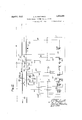
- Fig. 2 shows trackway apparatus of a similar system, except that traffic is controlled for both vdirections of travel without in anyway detractingfrom the reliability of the system ⁇ or the operating characteristics of the system insofar as the car-carried apparatus is concerned.
- This inventionl is an improvement on the invention shown in "the pat-ent to Theodore Bodde, No. 1,843,895 dated February 2, 1932.
- the railway track hasV been conventionally illustrated by traclr rails l, divided by wayside signals into blocks of which the block B and the adjacent ends of the blocks .A and C only have been shown, which wayside signals governtraiiic from left to right, as indicated by the direction of the arrow.
- vthe home, ⁇ signals HL f and H2, as well as their associated distant signals D1 and D2, respectively, are preferably manually controlled by levers located in asuitable tower.
- the levers for controlling the signals D1 and H1 have been omitted from the drawings.
- the signal D2 is controlled 'by the lever LD2 through the medium of a suitable mechanical connection conventionally shown by the dotted line 8.
- the two-position lhome signalH2 is mechanically controlled by the lever LH2 through the medium of a suitable mechanical connection such as a pipe line or cable, conventionally shown by the dott-ed line 4.
- the ramp 6 associated with the home signal H2 is one of the usual construction whereas the ramp ⁇ 7 associated with the distant signal D2 is one of the divided type, this ramp being divided somewhere near the middle by an insulating joint so that each half of the ramp may be separately connected to a control wire.
- the home ramp 6 has .a rectifier 8 associated therewith, and the distant ramp 7 has rectiliers 9 and 10 associated therewith.
- These rectifiers are preferably rectifiers of the copper oxide type, and have beenshown by arrows the points of which contact against cross lines. yThis conventional representation by the arrow thereof also signifies the direction in which current may flow through th-e-rectiiier. For instance if the arrow points toward the ramp in the cir-cuit, this fact signifies that the ramp is arranged for positive rectilication, and vice versa.
- the car-carried apparatus which is mounted on the locomotive co nventionally shown bythe wheels and axle 12, includes a motorgenerator G, preferably driven by a suitable turbine (not shown) which generator generates direct current at the brush-es 13 and generates alternating current at the brushes 14,
- the brushes 14 being connected to the primary winding of transformer 15.
- a shoe 17 pivotally supported as by pin 18, which shoe is adapted to co-operate with the ramps 6 and 7.
- the car-carried apparatus also includes'a polyphase alternating current relay MR of the induction type, the two windings 25 and '26 of which are connected inV multiple, these windings having individually contained in series therewith the rectiliers 27 and 28.
- the car-carried apparatus also includes a stick relay SR, an audible signal or bell BL a caution brake Vcontrol device or valve CV, and a stop brake control device or valve SV. It is believed the novel features as well as the operating characteristics of the invention will be best understood by considering the operation ofthe system.
- the caution valve CV is energized through the following circuit beginning at the positive bus ibus, wire 30, shoe contact 19, Wires 32, 33 and 34, winding 35 of the caution valve V, wire 36, to the negative bus, marked bus.
- the stop valve SV is
- This circuit of rather high ohrnic resistance allows alternating current of small Value to flow, which alternating current is substantially in phase with the voltage producing it, namely, the voltage or" the secondary winding of the transformer 15. ⁇
- the circuit including the winding of the relay is a highly inductive circuit, and the pulsating current flowing therein lags behindthe voltage producing it.
- this auxiliary Winding 8O is to make this relay slow-dropping without in any way impairing its stick-up characteristics, this winding 80 acting as a slug or bucking coil when shortc'ircuited by the Contact 81, causes the stick relay SR to have slow-dropping characteristics for reasons well understood by those skilled in the art.
- the closure ofthe circuit just traced causes the main relay MR to move to its left-hand caution position, thereby closing the following circuit for the upper winding of the stop valve SV z-beginning at the positive bus, wire 55, contact 56 of the main relay MR assuming its left-hand position, Wire 72 and 77, Winding 7 S of the stop valve SV, wire 39, back to the negative bus.
- the stop valve SV is thus maintained energized, but the caution valve CV is no longer energized, because the stick relay SR has not been picked up and the shoe contact 19 is no longer in its normal solid line position.
- the caution valve thus assumes its retracted position, thereby admitting air into the brake pipe by allowing it to flow through the whistle W, this Whistle allowing sufficient air to flow to effect a full service brake application, and at the same time informing the engineer that the brakes are being applied.
- the engineer now, if he so desires and is alert and physically able to do so, may manually operate the armature of the caution valve to its attracted position thereby preventing further admission of air into the brake pipe.
- the armature of the caution valve CV is preferably located so as to be readily accessible to the engineer without leaving his seat; whereas the armature of' the stop valve SV is located where it can not be readily reached, and may be accessible only from the ground. If the engineer holds the armature of the caution valve in its raised position until the train has moved ofi of the ramp 7 no complete brake application will take place. Attention is directed to the fact that the main relay MR will remain in its left-hand caution position throughout the entire time that the shoe 17 is in engagement with the ramp 7, this because the two halves of the ramp 7 are connected together when the distant signal D2 and the lever LD2, controlling the same, assume their normal stop position. The train may thus proceed to the home signal H2 if the engineer has acknowledged his vigilance by holding the armature or caution valve CV in its attracted position. ⁇ Y
- Applicant has thus provided a system which is decidedly economical in construction and operation, in that no trackway energy is required, merely inert rectifiers being used for giving distinctive indications in a safe way. Attention is further directed to the fact that in spite of the fact that a recti- Iier can only give two distinct indications of itself depending upon the direction in which it is connected in the circuit, applicant has been able to transmit four distinct indications from the trackway to the vehicle, namely, (l) clear without an audible signal, by connecting a rectifier between the ramp and the ramp connected to permit the free flow.V
- the system' is immune to response from direct current alone or from alternating current alone, the system requiring the flow of pulsating current and alternating current displaced in phase therewith which as heretofore pointed out is accomplished by the employment of an external rectifier located along the track way. Further, the system disclosed is very economical in that no source of current is required along the wayside, all of the current required for operation of the system being carried by the train itself.
- the track way apparatus shown in Fig. l is laid out for double track work, that is, for a track on which traflic may only move in one direction, namely in the direction of the arrow.
- trafiic may travel in both directions, as indicated by the two arrows.
- This trackway apparatus also includes signals on both sides of the track, one group of which is for governing train travel in one direction and the other group of which is for governing train travel in the other direction.
- the middle of the track is chosen so that only one, and a rather narrow, notch need be cut in snow plows to permit clearing ⁇ of such ramps. Also, if the ramps arel so located, the same car shoe may be used for the locomotive when operating eitherpilot or tender first.
- this ramp 1,15 is, arranged for positive rectification through the following circuit z-beginning at the track rails 100, wire 116, rectifier 117, wires v118 and 119, contact 120 of the lever LEH, wire 121, signal blade 122 of the signal EH and assuming the dotted clear position, wires'123 and 124 to the ramp 115; a clear influence is transmitted to the vehicle carried apparatus without the sounding ofthe audible signal. It is thus seen that the proper indications aretransmitted to the car-carried apparatus under clear traffic conditions of the ramps for a particulardirection of traffic.
- thewright-.hand portion of thera-il 101 will be arranged for negative rectification through the following circuit :V-beginning at the right-hand portion of ramp 101, wire 112, Contact 111 ofthe lever LVH, wires 110 and 109, through the rectifier 108, to the track rails 100. Under this condition of the ramp 101 a caution influence will then ⁇ be transmitted to a passing vehicle'effecting de-energization of thecaution valve CV.
- the ramp 115 will be arranged for positive rectifica tion through the following circuit beginning at the track rail 100, wire 116, rectifier 117, wires 118 and 127, contact blade 128 of the lever LVVH, wire 129, signal contact blade 130 of the signal ⁇ WH, wires 131 and 124, to the ramp 115.
- the left-hand portion of the ramp 101 will be arranged for positive rectification through the following circuit z-beginning at the rail 100, rectifier 102, wires 103, 188 and 135, lever LWH, wire 107, to the left-hand portion of the ramp 101. It is thus seen that both the right-hand part and left-hand part of the ramp 101 are arranged for positive rectification, from whichV it appears that a clear traflic impulse will be transmitted to the vehicle unaccompanied by a clear audible signal. This for the reason that the indication is the same as it is when passing over a clear home signal ramp.
- Applicant has thus disclosed a train control system having many features of safety and economT and in which four different distinctive traflic conditions may be transmitted from the trackway to the vehicle through the medium of inert ramps, these ramps requiring no trackway energy.
- the carcarried apparatus is of such construction that it may be used on either double track or single track railroads, and in the event it is used on single track railroads, in which traiiic may nieve in both directions, no clear audible signal is given when the vehicle carried apparatus moves by ramps associated with signals for the reverse direction, which signals are in the stop position.
- the apparatus will function properly if the locomotive is turned around, and is operated tender first, instead of pilot first, providing the locomotive is moving in the direction in which traffic is to move at that time.
- An automatic train control system of the shoe-and-ramp type comprising; carcarried apparatus including a stick relay which may be picked up if this apparatus cooperates with a ramp to permit current kof one polarity to flow, a stick circuit for said stick relay closed only when the shoe of said apparatus is in its raised position, an audible signal, and means for sounding said audible signal when said stick relay is in its attracted position and current of the reverse polarity may flow from said ramp to said apparatus.
- An automatic train control system of the shoe-and-ramp type comprising; ramps along the trackway for transmitting conductive control impulses to the vehicle, and carcarried apparatus on the railway vehicle constructed to manifest proceed traffic conditions without an audible signal when passing a ramp having one kind of electrical characteristic, manifest caution traffic conditions when passing a ramp having another kind of electrical characteristic, manifesting stop when passing a disconnected ramp, and manifesting proceed traflic conditions together with an audible signal when passing a ramp the first part of which has said one kind of electrical characteristic and the second part of which has the other kind of electrical characteristic.
- a train control system of the shoeand-ramp type the combination with a ramp along the track which may be energized or ⁇ deenergized electrically, a shoe on a railway vehicle, brake control means on the vehicle which is normally energized through contact means directly operated by the shoe, and which Contact means is open so long as said shoe rides on a ramp, and a stick relay which if energized remains energized so long as said shoe rides on such ramp irrespective of whether or not said ramp is energized for independently energizing said brake control means.
Landscapes
- Engineering & Computer Science (AREA)
- Mechanical Engineering (AREA)
- Train Traffic Observation, Control, And Security (AREA)
Description
April 5, 1932. c. s. BUSHNELL TRAIN CONTROL SYSTEM FOR RAILRoAns 2 Sheets-Sheet l Filed July 22, 1929 April 5, 1932 c. s. BUSHNELL TRAIN CONTROL SYSTEM FOR RAILROADS 2 Sheets-Sheet 2 lNVE OR BY'M ZM TTORNEY l QS Y n N :y 1 lfly w N 4 M @su m2 mm/E5 TQS E man m: o: N:\ V1 Ill llllll l,| l IIIPII .|I-| V Jr x m. E: sm um 2 m\ n: @A s2 aum VJ e: 1L h2 a; A 162 |i|||1|l on l o L LU .il 15H31 T JN b2 Y (Il m mWHl/w 2 dem; ow VA|11| ll. v\ k Nw Tm s, um i I l l I l i l [il |||lll||||l|ll|||||||| q Illlhilll Patented Apr. 5, 1932 rara naar.
CHAP-LES S; BUSHNELL, OF INOCI-VSTER, NEW YORK, ASSIGNOR TO GENERAL RAILWAY Y sie-net coMPANY, or, noci-rnsTnR,` NEW YORK TRAIN coivTnoI.i SYSTEM non RATLROADS .eppiieanon filed" July 2.2, 1929. serial No. 379,950. v
rihis invention relates to automatic train control systems, and more particularly-to systems of the inert ramp type. j I.
By inert 'ramp type, isineant an automatic train control` system in which .control influences are transmitted from a fixed ramp with which a shoe on the car is adapted to cooperate, which is capable of transmitting a plurality of distinctive conditionswwitfh'out the requirement of a sourceof'current along the tracl way. 1n accordance with the present invention, it is proposed to transmit distinctive control influences from a track way to a moving vehicle through the medium of electrical currents carried-through the ramp on the track and a shoe on the car, the distinctiveness of control being determined byopening the circuit so established and by inserting a rectifier in such circuit poled either in one direction or the other. Further, objects of the present invention reside in the provision of means whereby an additional distinctive control influence may be transmitted from theV traclzway to the vehicle this distinctive control comprising two ot the already considered controls spaced very closely together, this additional control being vdistinctive by reason of the sequential nature of two closely spaced successive control'iniiuences without an intervening disengagement of the car shoe with the ramp. 1
@ther objects, purposes and characteristic features of the invention include the provision of car-carried and track way apparatus in which the ramps are located in the middle of the track, and in which the ramps may be properly controlled for both directions of travel thereover.
Other objects, purposes and characteristic features of the present invention will 'in' part be pointed out hereinafter and will in part be obvious from the accompanying drawings.
ln describing the invention in detail reference will be made to the.` accompanying drawings in which :-l f f l shows the invention applied to a railway signalling system of the manually operable type employing two-position home and distant signals; and
Fig. 2 shows trackway apparatus of a similar system, except that traffic is controlled for both vdirections of travel without in anyway detractingfrom the reliability of the system` or the operating characteristics of the system insofar as the car-carried apparatus is concerned. y This inventionl is an improvement on the invention shown in "the pat-ent to Theodore Bodde, No. 1,843,895 dated February 2, 1932. Referring to F ig. l of the drawings, the railway track hasV been conventionally illustrated by traclr rails l, divided by wayside signals into blocks of which the block B and the adjacent ends of the blocks .A and C only have been shown, which wayside signals governtraiiic from left to right, as indicated by the direction of the arrow. In the particular arrangement shown vthe home,` signals HL f and H2, as well as their associated distant signals D1 and D2, respectively, are preferably manually controlled by levers located in asuitable tower. For convenience the levers for controlling the signals D1 and H1 have been omitted from the drawings. The signal D2 is controlled 'by the lever LD2 through the medium of a suitable mechanical connection conventionally shown by the dotted line 8. Similarly, the two-position lhome signalH2 is mechanically controlled by the lever LH2 through the medium of a suitable mechanical connection such as a pipe line or cable, conventionally shown by the dott-ed line 4. The ramp 6 associated with the home signal H2, is one of the usual construction whereas the ramp `7 associated with the distant signal D2 is one of the divided type, this ramp being divided somewhere near the middle by an insulating joint so that each half of the ramp may be separately connected to a control wire. The home ramp 6 has .a rectifier 8 associated therewith, and the distant ramp 7 has rectiliers 9 and 10 associated therewith. These rectifiers are preferably rectifiers of the copper oxide type, and have beenshown by arrows the points of which contact against cross lines. yThis conventional representation by the arrow thereof also signifies the direction in which current may flow through th-e-rectiiier. For instance if the arrow points toward the ramp in the cir-cuit, this fact signifies that the ramp is arranged for positive rectilication, and vice versa.
The car-carried apparatus, which is mounted on the locomotive co nventionally shown bythe wheels and axle 12, includes a motorgenerator G, preferably driven by a suitable turbine (not shown) which generator generates direct current at the brush-es 13 and generates alternating current at the brushes 14,
the brushes 14 being connected to the primary winding of transformer 15. Near the lower middle part of the locomotive or car is mounted a shoe 17 pivotally supported as by pin 18, which shoe is adapted to co-operate with the ramps 6 and 7. This shoe 17in addition to its co-operation with the ramps 6 and 7 as by contacting the same, is alsolifted, and therebymoves the Contact 19 from its normal to its dotted position, through the medium of a push rod 2O mounted in stationary supports 21 and 22.
The car-carried apparatus also includes'a polyphase alternating current relay MR of the induction type, the two windings 25 and '26 of which are connected inV multiple, these windings having individually contained in series therewith the rectiliers 27 and 28. The car-carried apparatus also includes a stick relay SR, an audible signal or bell BL a caution brake Vcontrol device or valve CV, and a stop brake control device or valve SV. It is believed the novel features as well as the operating characteristics of the invention will be best understood by considering the operation ofthe system.
Operation- Let us assume that the operator in the tower T wishes to allow a train to pass from left to right into the block at the entrance of which the home signal H2 is located. In order to do so the operation must clear the signals D2 and H2, which is accomplished by moving his levers LD2 and LH2 from their normal solid line to their dotted line positions. Such movement of the levers LD2 and LH2 causes the signals D2 and H2 to assume their inclined proceed position through the medium of the mechanical driving connections 3 and 4, respectively. Also, with th-e levers LD2 and LH2 in their dotted position the ramp 6 and the front part of the ramp 7 will be so connected that current may readily flow from the track rail 1 to these ramp portions but will not readily flow in the opposite direction. That is, both the left-hand part of ramp 7 and the entire ramp 6 will be arranged for positive recti- Iication.
Let us now consider the normal condition of the car-carried apparatus, and then observe the functioning thereof under various roadside conditions. Under normal clear traffic conditions of the apparatus, as shown, the caution valve CV is energized through the following circuit beginning at the positive bus ibus, wire 30, shoe contact 19, Wires 32, 33 and 34, winding 35 of the caution valve V, wire 36, to the negative bus, marked bus. Similarly, the stop valve SV, is
held in its energized position through the medium ofV current fiowing in the following circuit z-beginning at the positive bus, wire 30, shoe contact 19, wires 32, 33 and 37, lower winding 38 of the stop valve SV, wire 39, to the negative bus. Y
Attention is directed to the fact that the caution valve CV and the stop valve SV when energized will not have their armatures assume the attracted position, as shown, unless these armatures 40 and 41 are manually moved to such attracted positions. In other words, these valves CV and SV have stick or holding characteristics, and if once de-energized lmust have their energizing circuit reclosed and must be manually restored before they will remain in their normal attracted position. As structurally shown, the caution valve CV controls the plunger 42 and the stop valve SV controls the plunger 43.
As shown, it is assumed that the vacuum type air-brake system is used, and when these valves CV and SV are in their raised positionsthey prevent the How of air into the brake pipe BP. Also the caution valve CV when de-energized will not only admit air to the brake pipe BP, but will also sound the caution whistleWV. The stop valve SV, on the other hand allows admission of air into the brake pipe rather quietly, without audibly informing the engineer of this fact.
.Let us now assume that the train under consideration moves from leftto right, and shoe 17 engages and rides up the left end approach of the ramp 7, and in so doing opcrates the shoe contact 19 from its position shown to its dotted line position. This opens the circuits for the windings 35 and 38, and completes the following circuit for the main relay MR r--beginning at the secondary winding of the transformer 15, wire 45, rectifier 27, relay winding 25, Wire 46, wheels and axle 12, track rail 1, wire 47, rectifier 9, lever LD2 in reverse position, wire 48, contact 49 of the signal D2 in its reverse or dotted position, wire 50, left-hand portion of ramp 7 shoe 17, Wire 51, back to the secondary winding of transformer 15. The presence of the circuit just traced allows heavy pulsating current to flow in the winding 25 of the main relay MR. Simultaneous with the closure of the circuit just traced another circuit is closed which includes identically the same apparatus, except that the relay winding 26 and the iectifier 28 are included instead of the relay 25 and the rectifier 27. Attention is directed to the fact that in this latter circuit the rectifiers 9 and 28 are connected in opposition, so that the rectifying action in one direction is substantially the same as the rectifier action in thev other direction, and so that in reality a circuit of rather high ohmic resistance results. This circuit of rather high ohrnic resistance allows alternating current of small Value to flow, which alternating current is substantially in phase with the voltage producing it, namely, the voltage or" the secondary winding of the transformer 15.` The circuit including the winding of the relay, on the other hand, is a highly inductive circuit, and the pulsating current flowing therein lags behindthe voltage producing it. The flow of these two currents in the windings of the main relay MR, the waves of these currents being displaced in phase, causes the relay MR to be operated to the right-hand or clear position, thereby closing the following circuit for the winding of the'caution valve CV and winding 38 of the stop valve SV :ebeginning at the positive bus, wire 55, contact 56 of relay MR assuming its right-hand position, wires 57, 58, 59, and 33, the windings 35 and 38 in multiple, to the negative bus.' l in this connection attention is directed to the fact that the shoe contact 19 is now in its dotted position, and if it were not for the circuits just traced the valves CVand SV would have assumed their retracted position as will now be explained. Y
i/Vith the main relay MR in its right-hand clear position the following circuit for the upper winding of the stick relay SR is closedi-beginning at the positive bus, wire 55, Contact 56 of relay MR in its right-hand clear position, wires 57 and 60, shoe contact 19 in its dotted position, wire 61, upper winding 62 of the stick relay SB, wire 63, to the negative bus. The closure of this pick-up circuit for the stick relay SR, causes the relay SR toassurne its energized position thereby closing the following stick circuit, which remains close-d so long the shoe contact 19 is in its raised position beginning at the positiv-abus, wires and 65, front stick contact 66 of the relay wires 67, 58, and 60, shoe contact 19, wire 61, winding 62 of the relay SR, wire 63 to the negative bus.
Further, with the relay SR once stuck up through the stick circuit just traced, itis apparent that this relay SR will remain in its stuck-up position until the shoe contact 19 is moved from its dotted position. Jalso, with the relay SR in its energized position the windings 35 and 38 of the caution valve CV and the stop valve SV will be energized through the following circuit r-beginning at the positive bus, wires 55 and 65, front contact 66 of the relay SR, wires 67, 59, and 33, the windings 35 and 38 in multiple, back to the negative bus. It thus appears that the brake valves CV and SV r ill remain in their energized and attracted position so long as the shoe 17 remains in its raised position, this because the stick relay SR will remain up so long as contact 19 remains in its dotted position. Also, the stick relay SR would not have been picked up had not the first part ofthe ramp been arranged for positive rectification, that is, connected to the arrow end of a rectifier having its opposite terminal connectedto the track rail.
Let us now observe what happens when the shoe 17 moves from the first'part to the second part of the ramp 7 As the shoe 17 engages the second part. of the-ramp 7,y reci tifier current may flow more freely through the winding 26 of the main relay MR than through the winding 25, because the rectifiers 10 and 28 are now cumulatively` arranged in the circuit, whereas the rectifier-s 10 and 27 are connected in opposition in their circuit, the circuit for vthe winding 26 of the relay MR with the vshoe`17 engaging the second part-of the ramp 7 being traced as follows z-beginning at the secondary winding of the transformer l5, wire 51,'shoe 17, right-hand portion of ramp 7, wire 70, rectifier 10, rail 1, wheels and arde 12, wire 46, winding 26 of the main relay MR, rectifier 28, back to the secondary winding of transformer 15. rihis circuit allows a pulsating current to flow, of substantial value, and since the circuit just traced is highly inductive the pulsating current flowing therein will lag considerably behind the voltage producing it. Simultaneous with theV closure of the circuit just traced another `circuit is closed, which is identical to the circuit just traced except that the winding 25 and rectifier 27 are included instead of the winding 26 and rectifier 28. In this latter circuit the rectifier l() along the track and the rectifier 27 on the car are connected in rectifying opposition, so that very little rectifying action, if any, is going on in this circuit, thus resulting in a circuit of rather Vhigh ohmic resistance allowing the'flow of alternating current which is substantially in phase with the voltage producing it, namely, the voltage of the secondary winding 0f transformer 15.
The flow of currents in the two circuits just traced, these currents being displaced in phase, causes the main relay MR to assume its left-hand or caution position, in which the following circuit for sounding'the audible signal or bell BL is closed :#beginning at the positive bus, wire 55, contact 56 of the main relay M, assuming its lefthand position, wires 72 and 73, front contact 74 of the stick relay SR, wire 75, winding of the bell BL, wire 76 back to the negative bus.
Further, with the stick relay SR energized and the main relay MR assuming its left-v hand position the following circuit for the upper winding of the stop valve SV is closed :beginning at the positive bus, wire 55, contact 56 of the main relay MR assuming its left-hand position, wires 72 and 77, winding 7 8 of the stop valve SV, wire 39 to the negative bus. The closure of the circuit' to the audible signal BL obviously causes Vsounding of this audible signal and informs contact 81 when the stick relay SR assumes its attracted position. The purpose for this auxiliary Winding 8O is to make this relay slow-dropping without in any way impairing its stick-up characteristics, this winding 80 acting as a slug or bucking coil when shortc'ircuited by the Contact 81, causes the stick relay SR to have slow-dropping characteristics for reasons well understood by those skilled in the art.
As the train precoces and the shoe 17 moves off of the ramp 7 trie shoe contact 19 is returned to its normal position, and the caution and stop valves CV and SV are again energized through the normal circuit heretofore traced and including the shoe contact 19, so that the train proceed without any interference by the train control apparatus, this apparatus merely having informed the engineer by he sounding of the audible signal BL that he has ust passed a'clear ramp at a distant signal.
Let us now observe the functioning of the system as the train approaches the home signal H2, and the shoe 17 rides upon the ramp 6. As the shoe 17 rides upon the ramp V6 the shoe contact 19 moved from its normal to its dotted position and the main relay MR is moved to its right-hand clear position, by reason of the closure of the following circuit z--beginning at the secondary winding of the transformer 15, the windings 25 and 26 with their respective rectifiers 27 and 28 in multiple, wire 46, wheels and axle 12, track rail 1, wire 85, lever lul-l2, in reverse position, wire 86, signal contact S7 assuming' the dotted position, wire 89, rectifier 8, ramp 6, shoe 17, wire 51, back to the secondary winding'of transforn'ier'l. With the relay MB aga-in assuming its right-hand clear position the stick relay SR is picked up and the air brake valves CV and SV are held up for reasons heretofore explained.
As the shoe 17 moves off of the ramp 6 the car-carried apparatus will remain in its clear conditi-on without effecting cle-energization of the valve CV or the valve SV. The only distinction. in the control effected as the train proceeds by the rampG as distii `shed from thev functioning` when it pass theramp 7, is that no audible signal was sounded (hiring the passage of the train by the ramp 6, the main relay not being operated to its left-hand position as was the case when the shoe 17 engaged the second half of the ramp 7. In other Words, the train upon passing ramps 7 and 6 sounded the audible signal BL at the ramp 7 but did not sound this audible signal When passing the ramp 6, and in each case a clear controlling iniiuence was transmitted to the car-carried appara-tus in that neither of the valves CV and SV were de-energized during the movement of the train by the ramps 7 and 6, While the levers LD',l and LH2 assumedtheir dotted proceed position. Putting it another way, two distinctive kinds of clear control influences can be transmitted to the vehicle as follows clear with audible and clear Without audible.
Let us now observe the functioning of the apparatus when the levers LD2 and LH2 assume their normal solid line positions as the train in question approaches from left and moves in the normal direction of traiic. As the car shoe 17 is moving from left to right it engages the ramp 7 causing it to be lifted thereby, thus operating the shoe contact 19 to its dotted position. Also, the engagement of the shoe 17 with the ramp 7 effects closure of the following circuit z-beginning at the winding of the transformer 15, Wire 51, shoe 17, ramp 7, wire 50, signal Contact 49 in its normal restrictive caution position, Wires 90, 91 and 70, rectifier 10, track rail 1, Wheels and axle 12, wire 46, the windings 25 and 26 of the relay MR in multiple together with their respective rectifiers 27 and 28, back to thersecondary winding of transformer 15. The closure ofthe circuit just traced causes the main relay MR to move to its left-hand caution position, thereby closing the following circuit for the upper winding of the stop valve SV z-beginning at the positive bus, wire 55, contact 56 of the main relay MR assuming its left-hand position, Wire 72 and 77, Winding 7 S of the stop valve SV, wire 39, back to the negative bus. The stop valve SV is thus maintained energized, but the caution valve CV is no longer energized, because the stick relay SR has not been picked up and the shoe contact 19 is no longer in its normal solid line position. The caution valve thus assumes its retracted position, thereby admitting air into the brake pipe by allowing it to flow through the whistle W, this Whistle allowing sufficient air to flow to effect a full service brake application, and at the same time informing the engineer that the brakes are being applied. The engineer now, if he so desires and is alert and physically able to do so, may manually operate the armature of the caution valve to its attracted position thereby preventing further admission of air into the brake pipe.
In this connection it is desired to point out that the armature of the caution valve CV is preferably located so as to be readily accessible to the engineer without leaving his seat; whereas the armature of' the stop valve SV is located where it can not be readily reached, and may be accessible only from the ground. If the engineer holds the armature of the caution valve in its raised position until the train has moved ofi of the ramp 7 no complete brake application will take place. Attention is directed to the fact that the main relay MR will remain in its left-hand caution position throughout the entire time that the shoe 17 is in engagement with the ramp 7, this because the two halves of the ramp 7 are connected together when the distant signal D2 and the lever LD2, controlling the same, assume their normal stop position. The train may thus proceed to the home signal H2 if the engineer has acknowledged his vigilance by holding the armature or caution valve CV in its attracted position.` Y
Let us now observe what happens if the train reaches the home signal H2 inits normal stop position and the shoe` 17 is raised by ramp 6 in its stop condition. Attention is directed to the fact that the ramp 6 is entirely disconnected from the rail l with the home signal H2 in its stop position. As the shoe 17 is lifted by the ramp 6 the windingV 35 of the caution valve CV, as well as the winding 38 of the stop valve SV, is de-energized, because the shoe contact 19 is lifted -to the dotted position. The main relay MR under the conditions assumed will remain de-energized, theramp 6 being disconnected from the track rail 1, so that the valves CV and SV both become de-energized. Although the caution valve CV is de-energized it does not sound the whistle under the conditions assumed as it did when it was alone deenergized, this because the stop valve SV in its cle-energized position closes its normally open or back valve and isolates the caution valve from the brake pipe BP.
If the engineer should observe that the brakes are being applied and should lift the armature of the valve CV, this will avail him nothing since the sto valve will effect an immediate heavy bra re application, which cannot be prevented by the engineer without leaving his seat, since the stop valve SV is not readily accessible to the engineer.
Applicant has thus provided a system which is decidedly economical in construction and operation, in that no trackway energy is required, merely inert rectifiers being used for giving distinctive indications in a safe way. Attention is further directed to the fact that in spite of the fact that a recti- Iier can only give two distinct indications of itself depending upon the direction in which it is connected in the circuit, applicant has been able to transmit four distinct indications from the trackway to the vehicle, namely, (l) clear without an audible signal, by connecting a rectifier between the ramp and the ramp connected to permit the free flow.V
of current from the ramp to the rail (negative rectiiication) (8) caution by connectlng the ramp to the rail to permit the free flow of current from the ramp tothe rail (negative rectification)- and (4;) by entirely disconnecting the ramp from the rail and transmitting a stop impulse by lifting the shoe of the car-carried apparatus. i
The system disclosed, as already pointed out in detail in the prior application of Theo-` dore Bodde, is self-checking against crosses, and the like, by reason of the fact that two distinctive currents are required in the main relay MRin order to cause it to be moved to an energized position. For this reason, the
system' is immune to response from direct current alone or from alternating current alone, the system requiring the flow of pulsating current and alternating current displaced in phase therewith which as heretofore pointed out is accomplished by the employment of an external rectifier located along the track way. Further, the system disclosed is very economical in that no source of current is required along the wayside, all of the current required for operation of the system being carried by the train itself.
Single track equipment of Fig. 9.-The track way apparatus shown in Fig. l is laid out for double track work, that is, for a track on which traflic may only move in one direction, namely in the direction of the arrow. In the track way apparatus shown in Fig. 2 trafiicmay travel in both directions, as indicated by the two arrows. This trackway apparatus also includes signals on both sides of the track, one group of which is for governing train travel in one direction and the other group of which is for governing train travel in the other direction.
Let us again briefly summarize what effect each ramp conditionwill have on car-carried equipment. First, if the ramp is arranged for positive rectification clear traffic will be indicated on the vehicle without institution of an audible signal; second, ifa ramp is arranged fornegative rectification a caution indication is given on the vehicle effecting de-energization of the caution valves CV; third, if the ramp is entirely disconnected from the rails a danger indication will be transmitted to the vehicle, effecting de-energization of both the caution valve CV and the stop valve SV; and fourth, in the Vcase of the double ramp if the first portion isjarrangedfor positive rectification andthe sec-V for both directions of movement.
cation, clear traffic conditions will be manifested on the vehicle accompanied by the sounding of the audible signal BL.
From the foregoing considerations it is apparent that for single track work it will be necessary to so arrange the double ramp at ay distant signal, that for one direction of traffic -no audible signal will be given on the train under clear traffic conditions, ,whereas when a train passes over such ramp in the reverse direction under clear traffic conditions, an audible signal will be given. In this connection it shouldvbe understood that the ramps are located midway between the track rail 'and are engaged by the car shoe. Theramps are preferably located midway between the track rails, because these ramps must have their top surfaces located above the level of the track rails in order to let the shoe engage them and still clear crossings, Crossovers, and the like. Further, the middle of the track is chosen so that only one, and a rather narrow, notch need be cut in snow plows to permit clearing` of such ramps. Also, if the ramps arel so located, the same car shoe may be used for the locomotive when operating eitherpilot or tender first.
In order to get a clear understanding of the single track Varrangement shown in Fig. 2, bearing in mind that the car-carried apparatus of Fig. 1 is to be used in connectionV With the track way apparatus shown in Fig.
2, it is believed only necessary to consider how the ramps, under certain conditionsv of the levers LED, LWH, LEI-land LWD in the tower T, are arranged for rectification.
Let us assume that theV operator'in the tower T wishes traffic to movefrom left to.
right by the signals ED and EH-and into the block B. Y v
This is accomplished by moving thevlevers LEDand LEH Yto their dotted position, therebyreffecting clearing of the signals ED and EH through the medium of mechanical connections indicated by thedotted lines 94 and 95 respectively. Underthis'condition of the signals ED and EH as well as their controlling levers, the left part of the ramp 101 is arranged for positive rectification by reason of closure of the following circuit -beginning at the track rail 100, rectifier 102, wire 103, lever LED, wire 104, signal blade contactV 105 `in its dotted position, wire 106,
lever LVH in its normal position and wire Y Similarly, the-right-hand portion of the ramp 101 will be arranged for negative recti fication through the following circuit :M -loe-` ginning at the rail 100, rectifier 108, wires 109 "andi 110, contact blade 111 of the lever LVVH assuming its normal position, wire 112, to, the right-hand portion of the ramp 101. It it thus understood that Va train moving -from left `to right over the ramp 101 will festing clear trai'fic conditions.
have a :clear control influence transmitted thereto together with an audible signal mani-k If the train in question proceeds over the home ramp 115, associated withA the signal EH, this ramp 1,15 is, arranged for positive rectification through the following circuit z-beginning at the track rails 100, wire 116, rectifier 117, wires v118 and 119, contact 120 of the lever LEH, wire 121, signal blade 122 of the signal EH and assuming the dotted clear position, wires'123 and 124 to the ramp 115; a clear influence is transmitted to the vehicle carried apparatus without the sounding ofthe audible signal. It is thus seen that the proper indications aretransmitted to the car-carried apparatus under clear traffic conditions of the ramps for a particulardirection of traffic.
Let us now observe the character of the influences transmitted to the vehicle-when such vehicle is travelling from left to right over the rampslOl and 115, when the signals vED andEH and their associated levers LED and LEH are in their normal adverse traffic condition. Under this cond-ition the left-hand portion of the ramp 101 will be arranged for negative rectification by reason of completion of the following circuit z-beginnfing 'at the left-hand portion of ramp 101, wire 107, lever LWH, wire 106, contact blade 105, Wire 125, rectifier 108 to the track rails 100. Similarly, thewright-.hand portion of thera-il 101 will be arranged for negative rectification through the following circuit :V-beginning at the right-hand portion of ramp 101, wire 112, Contact 111 ofthe lever LVH, wires 110 and 109, through the rectifier 108, to the track rails 100. Under this condition of the ramp 101 a caution influence will then `be transmitted to a passing vehicle'effecting de-energization of thecaution valve CV.
As the train in question proceeds from left to right and passesover the ramp 115 this ramp 115 will be found to be disconnected from theV track rails because both the signals VH and are in Vtheir stop position and the signal blade contacts associated with these signals are open, so that; astop influence will be transmitted to the car-carried apparatus and both of the brake valves CV and SV are cle-energized and a brake application is imposed Which cannot be prevented by the engineer, all as already explained i'n connection WithiFig. 1. The ramps 101 and 115 Vthus function in' exactlythe same way as do the ramps .in Fig. 1 of the drawings `for traffic moving from left to right over these ramps.
Let us now observe what effect these ramps will have Vif West bound traffic moving from right to left, moves over these ramps 101 and 115. In order to set up west bound traffic' tionally shown by the dotted line 96. Obviously, with the signal WH and its associated lever LWH in their clear position, the ramp 115 will be arranged for positive rectifica tion through the following circuit beginning at the track rail 100, wire 116, rectifier 117, wires 118 and 127, contact blade 128 of the lever LVVH, wire 129, signal contact blade 130 of the signal `WH, wires 131 and 124, to the ramp 115.
Let'us now observe the condition of the ramp 101 for a train moving from right to left with the lever LWH and its associated signal vill-l in the stop position, and with the signals ND and WH and their associated levers in their proceed position. Under this condition the first part of the ramp 100 en-V countered, namely, the right-hand position is arranged for positive rectification through the following circuit z-beginning at the rail 100, rectifier 102, wires 103, 133 and 134, contact blade 111 of the lever Ll/VH assuming its dotted position, wire 112, to the right-hand portion of the ramp 101.
Similarly, the left-hand portion of the ramp 101 will be arranged for positive rectification through the following circuit z-beginning at the rail 100, rectifier 102, wires 103, 188 and 135, lever LWH, wire 107, to the left-hand portion of the ramp 101. It is thus seen that both the right-hand part and left-hand part of the ramp 101 are arranged for positive rectification, from whichV it appears that a clear traflic impulse will be transmitted to the vehicle unaccompanied by a clear audible signal. This for the reason that the indication is the same as it is when passing over a clear home signal ramp.
Applicant has thus disclosed a train control system having many features of safety and economT and in which four different distinctive traflic conditions may be transmitted from the trackway to the vehicle through the medium of inert ramps, these ramps requiring no trackway energy. Further, the carcarried apparatus is of such construction that it may be used on either double track or single track railroads, and in the event it is used on single track railroads, in which traiiic may nieve in both directions, no clear audible signal is given when the vehicle carried apparatus moves by ramps associated with signals for the reverse direction, which signals are in the stop position. Further, the apparatus will function properly if the locomotive is turned around, and is operated tender first, instead of pilot first, providing the locomotive is moving in the direction in which traffic is to move at that time.
Having thus shown and described a rather specific embodiment of the invention as ap- Y plied to double track and'single track work, it is desired to be understood that the particular circuit arrangements shown have been selected for the purpose of facilitating de'- scriptionl of the invention and its underlying principles rather than showing its scope or the exact structure preferably employed practicing the invention, and it is further desired to be understood that various changes, modifications and additions may be made'to adapt the invention to the particular railway system to which it is to be applied, such as automatic signalling, controlled automatically through track circuits, either for double track or single track work; all without departing from the spirit .or scope of the vpresent invention or the idea of means underlying the same, except as demanded by the scope of the following claims.
What 1 claim as new is p 1. An automatic train control system of the shoe-and-ramp type comprising; carcarried apparatus including a stick relay which may be picked up if this apparatus cooperates with a ramp to permit current kof one polarity to flow, a stick circuit for said stick relay closed only when the shoe of said apparatus is in its raised position, an audible signal, and means for sounding said audible signal when said stick relay is in its attracted position and current of the reverse polarity may flow from said ramp to said apparatus.
2. An automatic train control system of the shoe-and-ramp type comprising; ramps along the trackway for transmitting conductive control impulses to the vehicle, and carcarried apparatus on the railway vehicle constructed to manifest proceed traffic conditions without an audible signal when passing a ramp having one kind of electrical characteristic, manifest caution traffic conditions when passing a ramp having another kind of electrical characteristic, manifesting stop when passing a disconnected ramp, and manifesting proceed traflic conditions together with an audible signal when passing a ramp the first part of which has said one kind of electrical characteristic and the second part of which has the other kind of electrical characteristic.
3. In a train control system of the shoeand-ramp type, the combination with a ramp along the track which may be energized or` deenergized electrically, a shoe on a railway vehicle, brake control means on the vehicle which is normally energized through contact means directly operated by the shoe, and which Contact means is open so long as said shoe rides on a ramp, and a stick relay which if energized remains energized so long as said shoe rides on such ramp irrespective of whether or not said ramp is energized for independently energizing said brake control means.
4. In an automatic train control system of the shoe and ramp type, ramps along the trackway, a shoe on the vehicle which is raised upon passager of the vehicle by such ramp,
and Ineens on the vehicle which will respond only if said shoe is successively energized byV currents distinctive in character applied to the ramp While such ramp is lifting said shoe `Without an intervening lowering of said shoe, and including a stick relay that can only be picked up under one distinctive energy condition and an electro-responsive means that can only respond under another distinctive energy condition providing said stick relay is energized.
In testimony whereof I affix my signature.
CHARLES S. BUSHNELL.
Priority Applications (1)
| Application Number | Priority Date | Filing Date | Title |
|---|---|---|---|
| US379950A US1852555A (en) | 1929-07-22 | 1929-07-22 | Train control system for railroads |
Applications Claiming Priority (1)
| Application Number | Priority Date | Filing Date | Title |
|---|---|---|---|
| US379950A US1852555A (en) | 1929-07-22 | 1929-07-22 | Train control system for railroads |
Publications (1)
| Publication Number | Publication Date |
|---|---|
| US1852555A true US1852555A (en) | 1932-04-05 |
Family
ID=23499356
Family Applications (1)
| Application Number | Title | Priority Date | Filing Date |
|---|---|---|---|
| US379950A Expired - Lifetime US1852555A (en) | 1929-07-22 | 1929-07-22 | Train control system for railroads |
Country Status (1)
| Country | Link |
|---|---|
| US (1) | US1852555A (en) |
-
1929
- 1929-07-22 US US379950A patent/US1852555A/en not_active Expired - Lifetime
Similar Documents
| Publication | Publication Date | Title |
|---|---|---|
| US1852555A (en) | Train control system for railroads | |
| US2063336A (en) | Protective system for railways | |
| US2681984A (en) | Directional control system for railway track circuits | |
| US2078001A (en) | Railroad signaling system | |
| US1843895A (en) | Automatic train control system | |
| US2098719A (en) | Railway signaling system and apparatus | |
| US2313887A (en) | Railway traffic controlling apparatus | |
| US2255192A (en) | Coded continuous train control and cab signaling system for railroads | |
| US1492301A (en) | Signal and control system | |
| US1636348A (en) | Controlling apparatus for highway-crossing signals | |
| US1926864A (en) | Automatic train control system | |
| US1703831A (en) | Continuous inductive train-control system | |
| US1681903A (en) | Traijst control | |
| US829606A (en) | Railway-signal. | |
| US1797560A (en) | Railway-traffic-controlling apparatus | |
| US1605525A (en) | Train-control system for railroads | |
| US2063971A (en) | Railway signaling system | |
| US2003265A (en) | Railway signaling system | |
| US2026489A (en) | Railway traffic controlling system | |
| US1703844A (en) | Train control | |
| US1622285A (en) | Cab-signal and teaikt-contbol system | |
| US1264720A (en) | Railway signaling system. | |
| US1552962A (en) | Alternating-current continuous-induction train-control system | |
| USRE17384E (en) | Automatic tbaiet contboxi | |
| US1492719A (en) | Railway-traffic-controlling apparatus |