US1852554A - Automatic train control system - Google Patents
Automatic train control system Download PDFInfo
- Publication number
- US1852554A US1852554A US194972A US19497227A US1852554A US 1852554 A US1852554 A US 1852554A US 194972 A US194972 A US 194972A US 19497227 A US19497227 A US 19497227A US 1852554 A US1852554 A US 1852554A
- Authority
- US
- United States
- Prior art keywords
- reset
- relay
- train
- valve
- train control
- Prior art date
- Legal status (The legal status is an assumption and is not a legal conclusion. Google has not performed a legal analysis and makes no representation as to the accuracy of the status listed.)
- Expired - Lifetime
Links
- 238000004804 winding Methods 0.000 description 11
- 238000004891 communication Methods 0.000 description 3
- 230000003111 delayed effect Effects 0.000 description 2
- 230000001939 inductive effect Effects 0.000 description 2
- 238000000034 method Methods 0.000 description 2
- 238000012986 modification Methods 0.000 description 2
- 230000004048 modification Effects 0.000 description 2
- 208000036366 Sensation of pressure Diseases 0.000 description 1
- 230000002411 adverse Effects 0.000 description 1
- 230000000994 depressogenic effect Effects 0.000 description 1
- 230000000977 initiatory effect Effects 0.000 description 1
- ZRHANBBTXQZFSP-UHFFFAOYSA-M potassium;4-amino-3,5,6-trichloropyridine-2-carboxylate Chemical compound [K+].NC1=C(Cl)C(Cl)=NC(C([O-])=O)=C1Cl ZRHANBBTXQZFSP-UHFFFAOYSA-M 0.000 description 1
- 230000000717 retained effect Effects 0.000 description 1
- 230000011664 signaling Effects 0.000 description 1
Images
Classifications
-
- B—PERFORMING OPERATIONS; TRANSPORTING
- B61—RAILWAYS
- B61L—GUIDING RAILWAY TRAFFIC; ENSURING THE SAFETY OF RAILWAY TRAFFIC
- B61L3/00—Devices along the route for controlling devices on the vehicle or train, e.g. to release brake or to operate a warning signal
- B61L3/02—Devices along the route for controlling devices on the vehicle or train, e.g. to release brake or to operate a warning signal at selected places along the route, e.g. intermittent control simultaneous mechanical and electrical control
- B61L3/08—Devices along the route for controlling devices on the vehicle or train, e.g. to release brake or to operate a warning signal at selected places along the route, e.g. intermittent control simultaneous mechanical and electrical control controlling electrically
- B61L3/12—Devices along the route for controlling devices on the vehicle or train, e.g. to release brake or to operate a warning signal at selected places along the route, e.g. intermittent control simultaneous mechanical and electrical control controlling electrically using magnetic or electrostatic induction; using radio waves
- B61L3/121—Devices along the route for controlling devices on the vehicle or train, e.g. to release brake or to operate a warning signal at selected places along the route, e.g. intermittent control simultaneous mechanical and electrical control controlling electrically using magnetic or electrostatic induction; using radio waves using magnetic induction
Definitions
- This invention relates in general to train control systems, and has more particular reference to a reset means for use in connection with an intermittent inductive type of system.
- a new and improved reset means More specifically it is proposed to provide a reset means which is pneumatic in character and includes both a cab reset device and a ground reset device, both of which are properly protected against misuse and which require the train to be brought to a full stop after having received an automatic brake application, before the resetting operation can be completed.
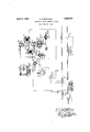
- the single figure is a schematic representation of oneform of the present invention shown in connection with a simplified form of train control system.
- the signals 3 controlling trackway inductors 4, in accordance with traffic conditions.
- the control means for the signals, and for the inductors have not been shown or described in detail as it is quite unnecessary for a complete understanding of the present invention. It is sufficient for present purposes to bear in mind that the inductors are controlled in accordance with trafiic conditions in any usual or desired manner, as will be well understood by those versed in this particular art, so as to make the inductors active under caution and danger trafiic conditions, and to make them inactive under clear traffic conditions.
- a receiver 6 Carried on the car, represented diagrammatically by wheels and axles 5, is a receiver 6, positioned to pass over the inductors in inductive relation thereto, and including primary and secondary windings P P and S S The primary windings are connected in series with each other, with a tuning condenser 7 and a source of current 8, shown as an alternator, delivering a current of a frequency preferably considerably higher than the usual commercial frequencies, as, for example, a current of about 360 cycles per second.
- the secondary windings are likewise connected in series with each other, with a tuning condenser 9, and the windings 10 of a main relay MR, having a pivoted armature l1 biased to retracted position by a tension spring 12, and normally held in at tracted position by current flowing in the secondary circuit due to voltages induced in the secondary windings 3 ,8 by transformer action from the primary windings P and P
- the apparatus thus far described operates to cause the main relay MB to assume either its attracted or retracted position according to traflic conditions.
- the magnetic linkage between the primary and secondary windings on the receiver 6 is substantially unaffected by passage over an inactive inductor 4, but is modified by an active inductor so as to reduce to zero, or at least to substantially decrease, the induced voltages in the secondary windings, whereby to deenergize relay MR and normally cause its armature 11 to drop.
- the particular co-action between the inductor and receiver will be well understood by those versed in this particular art and it should not be necessary to discuss it in detail for the purposes of the present invention. It is suflicient to bear in mind that the apparatus thus far described results in de-energizing the main relay MR upon entrance of the train into a caution or danger block but leaves the main relay energized upon passage into a clear block.
- the armature 11 of the main relay has mounted thereon a valve stem 13 carrying a valve B which controls communication of pipe 15 with atmosphere through a port 16 in the valve casing 16 for valve B.
- the system in question includes an aclniowledging device Arch, comprising contact fingers 17 and 18, the latter being slow to break its contact, and having a contact breaking time of approximately 15 seconds.
- a reset device which includes a cab reset valve CR, a ground reset valve GR, a timing reservoir TR, a reset sylphon RS, a reset rod 19, and a valve A carried by the reset rod and arranged to control communication between a conduit 20 and a port 21 leading to atmosphere.
- the reset sylphon includes a casing 22 within which is positioned a flexible chamber 23 which is normally expanded by a spring 24 and which contracts upon pressure being admitted into casing 22 either directly through the valve GR, or indirectly through the valve CR which can be operated to supply pressure through a r stricted passageway 25 to the timing reservoir TR, which pressure is then transferred through a second restricted passageway 26 to the casing 22.
- the cab reset valve CR has a port 27 leading to atmosphere for a purpose to be later described. Both of the reset valves CR and GR- control pressure from the main reservoir of a usual air brake system.
- a large actuator cylinder is shown at LAC, and, in the usual manner, operates to apply the car brakes upon pressure being vented therefrom, and this cylinder is supplied with main reservoir pressure through a port 28 and a restricted passageway 29 in a valve 30 having a right angle port 31 for connecting the actuator cylinder to the casings of valves A and B by way of a double heading cock DH.
- acknowledgment must be performed before armature 11 has dropped away, since with armature 11 down the acknowledging energizing circuit is detuned, and insufficient current will flow to cause the relay to pick up its armature.
- the acknowledging contactor can be released, since the normal induced current will then flow in the normal energizing circuit for the main relay.
- the acknowledging contactor is protected against misuse by having the acknowledging energizing circuit pass through the slow opening contact finger 18, whereby if the contactor is held depressed for longer than approximately 15 seconds, the acknowledging energizing circuit will be broken. The train can now proceed as before until another active inductor is encountered.
- the main relay MR will be de-energized to thereby open valve B and permit the large actuating cylinder to vent to atmosphere through the port 16, to thereby give an automatic brake application which is the penalty, in the present case, for failure to properly acknowledge under conditions calling for acknowledgment.
- the small port 29 acts as an air ejector when the valve B opens, and by its ejecting action causes the air in the cylinder LAC to be discharged very quickly thereby giving an immediate brake application.
- the engineer must have recourse to the reset device, and has a choice of two ways of resetting the apparatus. He can brin the train to a full stop, whereupon valve *R can be operated, this valve being accessible only from the ground, for example, to thereby put main reservoir pressure into casing 22. This admission of pressure operates to compress the reset sylphon RS, against the tension of spring 24, to thus raise rod 19, and physically reset armature 11 to its attracted position, where it will then be retained by the normal energizing circuit for the relay which is then retuned.
- valve A Vents the large actuator cylinder to atmosphere through port 21, and this provides a safeguard against improper operation 01": the ground reset valve GR, such for example, as leaving it in reset position.
- the ground reset valve GR such for example, as leaving it in reset position.
- An alternative method is open to the engineer, for resetting the apparatus, which permits him to accomplish the same without alighting from the train, as is sometimes most desirable, as when the train is on a trestle, or the like.
- This second method of resetting is accomplished by moving the cab reset valve GR, in a clockwise direction, to its reset position to thereby admit main reservoir pres sure into the timing reservoir TR.
- the timing reservoir is so proportioned that a time at least as long as the braking time for bring ing the train to a full stop under the most adverse braking conditions, is required to build up sufiicient pressure in the reservoir to compress the reset sylphon RS, and thus raise rod 19 to reset armature 11 of the main relay.
- valve A In order that the train can proceed, valve A must be again closed which requires that the reset sylphon be expanded by sprin 24, 'thus necessitating the return of cab reset valve OR to normal position to thereby vent timing reservoir TR to atmosphere through port 27.
- car carried apparatus including, means responsive to trackway conditions, brake control means controlled by said responsive means, means for preventing operation of the responsive means by trackway conditions, and a plurality of manually operable protected reset means, accessible for operation under dverent conditions of train operation, for restoring the responsive means after its operation in accordance with trackway conditions.
- car carried apparatus including, means responsive to track way conditions, train control means controlled by said responsive means, electrical means for preventing operation of the responsive means by trackway conditions, and a plurality of pneumatic reset means for restoring the responsive means after its operation in accordance with trackway conditions.
- car carried apparatus including, means responsive to trackway conditions, brake control means controlled by said responsive means, means for preventing operation of the responsive means by trackway conditions, and a plurality of manually operable reset means, differently protected against improper operation, for the responsive means.
- car carried apparatus including, means responsive to trackway conditions, train control means controlled by said responsive means, means for preventing operation of the responsive means by trackway conditions, a reset for the responsive means, including a delayed action element, positioned to be readily accessible at all times by the engineer, and a second reset means positioned to be accessible only when the train is at rest.
- car carried apparatus including, means responsive to track way conditions, train control means controlled by said responsive means, means for preventing operation of the responsive means by trackway conditions, a pneumatic reset for the responsive means including a delayed action element positioned to be readily accessible at all times by the engineer, and a second pneumatic reset means positioned to be accessible only when the train is at rest.
- a train control system means responsive to trackway conditions to assume either a normal or an operated position, train control means initiated upon operation of said responsive means, and pneumatic reset means, for moving the responsive means from operated to normal position, including a reset member, a readily accessible reset valve controlling a source of pressure, a timing chamber connecting the valve and member, and a second reset valve, controlling passage from a source of pressure to the reset member, and accessible only when the train is at rest.
- a relay responsive to trackway influences, a train con trol device initiated on release of said relay, manually operable means for preventing release of the armature of said relay on deenergization of the same by trackway influences, and pneumatic reset means for restoring the relay armature to attracted position including, pressure responsive means to mechanically restore the relay armature, and
- a manually operable valve accessible only when the train is at rest for supplying pressure to the pressure responsive means.
- a relay responsive to trackway influences, a train control device initiated on release of said relay, manually operable means for preventing release of said relay on deenergization of the same, pneumatic reset means for restoring the armature of said relay to attracted position including, pressure responsive means to restore the armature of said relay and to simultaneously initiate said train control device and a manually operable valve accessible only when the train is at rest for supplying pressure to the pressure responsive means.
- a relay responsive to trackway influences, a train c0ntrol device initiated on release of said relay, manually operable means for preventing release of said relay on deenergization of the same, pneumatic reset means for restoring the armature of said relay to attracted position including, pressure responsive means to restore the armature of said relay, a manually operable valve accessible only when the train is at rest for supplying pressure to the pressure responsive means, and a readily accessible valve, a timing reservoir arranged to be supplied with pressure by the accesible valve, and means connecting the reservoir to the pressure responsive means.
- a train control device operable to cause initiation of the train control device, and reset means for said member including, pressure responsive means, a timing element, a first means for connecting the pressure responsive means directly to a source of pressure, and a second means for connecting the pressure responsive means to a source of pressure through said timing element.
Landscapes
- Engineering & Computer Science (AREA)
- Mechanical Engineering (AREA)
- Braking Systems And Boosters (AREA)
Description
Han -inau u- %;%TORNEY' C. S-BUSHNELL AUTOMATIC TRAIN CONTROL SYSTEM Filed May 28, 1927 .m on GM April 5, 1932.
Patented Apr. 5, 1932 UNITED STATES PATENT OFFICE CHARLES S. BUSHNELL, OF ROCHESTER, NEW YORK, ASSIGNOR TO GENERAL RAILWAY SIGNAL COMPANY, OF ROCHESTER, NEW YORK AUTOMATIC TRAIN CONTROL SYSTEM Application filed. May 28,
This invention relates in general to train control systems, and has more particular reference to a reset means for use in connection with an intermittent inductive type of system.
In systems of the kind in question it is usual to stimulate the engineer into vigilance by requiring an acknowledging act under certain conditions and inflicting a penalty, such as an automatic brake application, it the acknowledgement is not properly performed. To relieve the train from automatic brake application it is also usual to provide reset means for returning the va- .1 rious parts to normal position and releasing the brakes, and such reset means are generally protected against misuse by requiring their operation from the ground, which under certain conditions is undesirable, or perhaps impossible.
With the above and other considerations in mind, it is proposed, in accordance with this invention, to provide, in combination with an acknowledging device, a new and improved reset means. More specifically it is proposed to provide a reset means which is pneumatic in character and includes both a cab reset device and a ground reset device, both of which are properly protected against misuse and which require the train to be brought to a full stop after having received an automatic brake application, before the resetting operation can be completed.
Further objects, purposes, and characteristic features of this invention will appear as the description progresses, reference being had to the accompanying drawing, showing, solely by way of example, and in awholly diagrammatic manner, one form which the invention can assume. In the drawing: 7
The single figure is a schematic representation of oneform of the present invention shown in connection with a simplified form of train control system.
Referring to the drawing, there is shown a stretch of trackway constituted by rails 1, divided in the usual manner into signalling locks by means of insulating joints 2, with a wayside signal 3 positioned at the entrance 1927. Serial No. 194,972.
end of each block, the signals 3 controlling trackway inductors 4, in accordance with traffic conditions. The control means for the signals, and for the inductors, have not been shown or described in detail as it is quite unnecessary for a complete understanding of the present invention. It is sufficient for present purposes to bear in mind that the inductors are controlled in accordance with trafiic conditions in any usual or desired manner, as will be well understood by those versed in this particular art, so as to make the inductors active under caution and danger trafiic conditions, and to make them inactive under clear traffic conditions.
Carried on the car, represented diagrammatically by wheels and axles 5, is a receiver 6, positioned to pass over the inductors in inductive relation thereto, and including primary and secondary windings P P and S S The primary windings are connected in series with each other, with a tuning condenser 7 and a source of current 8, shown as an alternator, delivering a current of a frequency preferably considerably higher than the usual commercial frequencies, as, for example, a current of about 360 cycles per second. The secondary windings are likewise connected in series with each other, with a tuning condenser 9, and the windings 10 of a main relay MR, having a pivoted armature l1 biased to retracted position by a tension spring 12, and normally held in at tracted position by current flowing in the secondary circuit due to voltages induced in the secondary windings 3 ,8 by transformer action from the primary windings P and P The apparatus thus far described operates to cause the main relay MB to assume either its attracted or retracted position according to traflic conditions. The magnetic linkage between the primary and secondary windings on the receiver 6 is substantially unaffected by passage over an inactive inductor 4, but is modified by an active inductor so as to reduce to zero, or at least to substantially decrease, the induced voltages in the secondary windings, whereby to deenergize relay MR and normally cause its armature 11 to drop. The particular co-action between the inductor and receiver will be well understood by those versed in this particular art and it should not be necessary to discuss it in detail for the purposes of the present invention. It is suflicient to bear in mind that the apparatus thus far described results in de-energizing the main relay MR upon entrance of the train into a caution or danger block but leaves the main relay energized upon passage into a clear block.
The armature 11 of the main relay has mounted thereon a valve stem 13 carrying a valve B which controls communication of pipe 15 with atmosphere through a port 16 in the valve casing 16 for valve B.
The system in question includes an aclniowledging device Arch, comprising contact fingers 17 and 18, the latter being slow to break its contact, and having a contact breaking time of approximately 15 seconds.
A reset device is provided which includes a cab reset valve CR, a ground reset valve GR, a timing reservoir TR, a reset sylphon RS, a reset rod 19, and a valve A carried by the reset rod and arranged to control communication between a conduit 20 and a port 21 leading to atmosphere. The reset sylphon includes a casing 22 within which is positioned a flexible chamber 23 which is normally expanded by a spring 24 and which contracts upon pressure being admitted into casing 22 either directly through the valve GR, or indirectly through the valve CR which can be operated to supply pressure through a r stricted passageway 25 to the timing reservoir TR, which pressure is then transferred through a second restricted passageway 26 to the casing 22. The cab reset valve CR, has a port 27 leading to atmosphere for a purpose to be later described. Both of the reset valves CR and GR- control pressure from the main reservoir of a usual air brake system.
A large actuator cylinder is shown at LAC, and, in the usual manner, operates to apply the car brakes upon pressure being vented therefrom, and this cylinder is supplied with main reservoir pressure through a port 28 and a restricted passageway 29 in a valve 30 having a right angle port 31 for connecting the actuator cylinder to the casings of valves A and B by way of a double heading cock DH.
The various rotary valves shown in the drawing can assume different positions in accordance with the arrow indications placed adjacent the valves in question.
The various parts have been shown in the drawing in their normal positions and conditions, that is, in the positions and conditions which exist under travel through clear territory. Assuming the car 5 to be traveling in a clear block, it will have passed over an inactive inductor at the entrance to such block so that the main relay will not have been (lo-energized but its armature will remain, as shown in the drawing, in attracted position, in which case the brake actuator cylinder is closed off from connection to atmosphere by the two valves A and B.
For the purpose of explanation, let us sume that car 5 passes into a caution or danger block so that the receiver 6 passes over an active inductor 4: at the entrance to such caution or danger block. In these circumstances the main relay MR is deprived of energizing current, but if the engineer acknowledges just before passing the inductor in question, he thereby completes an energizing circuit for the main relay which includes the source of energy 8, contact lingers 18 and 17 of A070, the windings 10 of relay MB, and the tuning condenser 9, whereby the relay will remain energized regardless of whether or not current be flowing through the secondary windings S and S of receiver 6. As pointed out below, acknowledgment must be performed before armature 11 has dropped away, since with armature 11 down the acknowledging energizing circuit is detuned, and insufficient current will flow to cause the relay to pick up its armature. As soon as the car has passed the inductor in question the acknowledging contactor can be released, since the normal induced current will then flow in the normal energizing circuit for the main relay. It will be noted that the acknowledging contactor is protected against misuse by having the acknowledging energizing circuit pass through the slow opening contact finger 18, whereby if the contactor is held depressed for longer than approximately 15 seconds, the acknowledging energizing circuit will be broken. The train can now proceed as before until another active inductor is encountered.
If we assume that the engineer, upon passing the active inductor referred to above, is not vigilant, and fails to acknowledge, the main relay MR will be de-energized to thereby open valve B and permit the large actuating cylinder to vent to atmosphere through the port 16, to thereby give an automatic brake application which is the penalty, in the present case, for failure to properly acknowledge under conditions calling for acknowledgment. It is desired to point out here that the small port 29 acts as an air ejector when the valve B opens, and by its ejecting action causes the air in the cylinder LAC to be discharged very quickly thereby giving an immediate brake application. On having passed the inductor in question, normal voltage is again induced in the secondary windings of the receiver, but with armature 11 retract-ed, the tuning of the energizing circuit for the relay is destroyed, and insufficient current flows to pick up the relay. It is therefore necessary, in order to relieve the train from the automatic brake application to pick up relay ME in some other manner. The engineer is powerless to reset the main relay by means of the acknowledging contactor, since with armature 11 down, the acknowledging energizing circuit is detuned and insuificient current will flow to pick up the relay.
Under the above set forth conditions, the engineer must have recourse to the reset device, and has a choice of two ways of resetting the apparatus. He can brin the train to a full stop, whereupon valve *R can be operated, this valve being accessible only from the ground, for example, to thereby put main reservoir pressure into casing 22. This admission of pressure operates to compress the reset sylphon RS, against the tension of spring 24, to thus raise rod 19, and physically reset armature 11 to its attracted position, where it will then be retained by the normal energizing circuit for the relay which is then retuned. Simultaneously with resetting armature 11, valve A Vents the large actuator cylinder to atmosphere through port 21, and this provides a safeguard against improper operation 01": the ground reset valve GR, such for example, as leaving it in reset position. With armature 11 in attracted position, valve B closes off communication between the large actuator cylinder and atmosphere through port 16, to thereby permit main reservoir pressure through port 28, to build up in the actuator cylinder and release the train from the automatic brake application, provided valve GR is returned to normal to permit valve A to close.
An alternative method is open to the engineer, for resetting the apparatus, which permits him to accomplish the same without alighting from the train, as is sometimes most desirable, as when the train is on a trestle, or the like. This second method of resetting is accomplished by moving the cab reset valve GR, in a clockwise direction, to its reset position to thereby admit main reservoir pres sure into the timing reservoir TR. The timing reservoir is so proportioned that a time at least as long as the braking time for bring ing the train to a full stop under the most adverse braking conditions, is required to build up sufiicient pressure in the reservoir to compress the reset sylphon RS, and thus raise rod 19 to reset armature 11 of the main relay. In order that the train can proceed, valve A must be again closed which requires that the reset sylphon be expanded by sprin 24, 'thus necessitating the return of cab reset valve OR to normal position to thereby vent timing reservoir TR to atmosphere through port 27.
lVith the apparatus above described, it will be seen that a very convenient and efi'ective reset means has been provided, whereby it necessary to bring the train to a full stop to relieve it of an automatic brake application incurred due to failure to properly acknowledge, and at the same time allows the engineer to choose whether he shall reset from the ground or from the cab.
While the present invention has been shown in connection with an intermittent system employing alternating current, it is clear that it might be used under certain condi tions in other types of systems and with direct current, and it is desired to be understood that the invention is not limited to the particular setting with which it is shown and described in the present specification.
The above rather specific description of one form of the invention, is given solely by way of example, and is not intended, in any manner whatsoever, in a limiting sense. Obviously, this invention can assume many dif ferent physical forms, and is susceptible of numerous modifications, and all such forms and modifications are intended to be included by this application, as come within the scope of the appended claims.
Having described my invention, I now claim 1. In a train control system, car carried apparatus, including, means responsive to trackway conditions, brake control means controlled by said responsive means, means for preventing operation of the responsive means by trackway conditions, and a plurality of manually operable protected reset means, accessible for operation under diilerent conditions of train operation, for restoring the responsive means after its operation in accordance with trackway conditions.
2. In a train control system, car carried apparatus, including, means responsive to track way conditions, train control means controlled by said responsive means, electrical means for preventing operation of the responsive means by trackway conditions, and a plurality of pneumatic reset means for restoring the responsive means after its operation in accordance with trackway conditions.
3. In a train control system, car carried apparatus, including, means responsive to trackway conditions, brake control means controlled by said responsive means, means for preventing operation of the responsive means by trackway conditions, and a plurality of manually operable reset means, differently protected against improper operation, for the responsive means.
4-. In a train control system, car carried apparatus, including, means responsive to trackway conditions, train control means controlled by said responsive means, means for preventing operation of the responsive means by trackway conditions, a reset for the responsive means, including a delayed action element, positioned to be readily accessible at all times by the engineer, and a second reset means positioned to be accessible only when the train is at rest.
5. In a train control system, car carried apparatus including, means responsive to track way conditions, train control means controlled by said responsive means, means for preventing operation of the responsive means by trackway conditions, a pneumatic reset for the responsive means including a delayed action element positioned to be readily accessible at all times by the engineer, and a second pneumatic reset means positioned to be accessible only when the train is at rest.
6. In a train control system, means responsive to trackway conditions to be changed from normal to operated position, brake ap plying means initiated upon operation of said responsive means, and a plurality of separate, manually operable, pneumatic reset means for each moving the responsive means from its operated, to its normal, position.
7. In a train control system, means responsive to trackway conditions to assume either a normal or an operated position, train control means initiated upon operation of said responsive means, electric means operable at times to prevent ope ation of the responsive means in accordance with trackway conditions, and a plurality of separate pneumatic means for moving the responsive means from its operated, to its normal, position.
8. In a train control system, means responsive to trackway conditions to assume either a normal or an operated position, train control means initiated upon operation of said responsive means, and pneumatic reset means, for moving the responsive means from operated to normal position, including a reset member, a readily accessible reset valve controlling a source of pressure, a timing chamber connecting the valve and member, and a second reset valve, controlling passage from a source of pressure to the reset member, and accessible only when the train is at rest.
9. In a train control system, a relay responsive to trackway influences, a train con trol device initiated on release of said relay, manually operable means for preventing release of the armature of said relay on deenergization of the same by trackway influences, and pneumatic reset means for restoring the relay armature to attracted position including, pressure responsive means to mechanically restore the relay armature, and
a manually operable valve accessible only when the train is at rest for supplying pressure to the pressure responsive means.
10. In a train control system, a relay responsive to trackway influences, a train control device initiated on release of said relay, manually operable means for preventing release of said relay on deenergization of the same, pneumatic reset means for restoring the armature of said relay to attracted position including, pressure responsive means to restore the armature of said relay and to simultaneously initiate said train control device and a manually operable valve accessible only when the train is at rest for supplying pressure to the pressure responsive means.
11. In a train control system, a relay responsive to trackway influences, a train c0ntrol device initiated on release of said relay, manually operable means for preventing release of said relay on deenergization of the same, pneumatic reset means for restoring the armature of said relay to attracted position including, pressure responsive means to restore the armature of said relay, a manually operable valve accessible only when the train is at rest for supplying pressure to the pressure responsive means, and a readily accessible valve, a timing reservoir arranged to be supplied with pressure by the accesible valve, and means connecting the reservoir to the pressure responsive means.
12. In a train control system, a train control device, a member operable to cause initiation of the train control device, and reset means for said member including, pressure responsive means, a timing element, a first means for connecting the pressure responsive means directly to a source of pressure, and a second means for connecting the pressure responsive means to a source of pressure through said timing element.
In testimony whereof I afliX my signature.
CHARLES S. BUSHNELL.
Priority Applications (1)
| Application Number | Priority Date | Filing Date | Title |
|---|---|---|---|
| US194972A US1852554A (en) | 1927-05-28 | 1927-05-28 | Automatic train control system |
Applications Claiming Priority (1)
| Application Number | Priority Date | Filing Date | Title |
|---|---|---|---|
| US194972A US1852554A (en) | 1927-05-28 | 1927-05-28 | Automatic train control system |
Publications (1)
| Publication Number | Publication Date |
|---|---|
| US1852554A true US1852554A (en) | 1932-04-05 |
Family
ID=22719570
Family Applications (1)
| Application Number | Title | Priority Date | Filing Date |
|---|---|---|---|
| US194972A Expired - Lifetime US1852554A (en) | 1927-05-28 | 1927-05-28 | Automatic train control system |
Country Status (1)
| Country | Link |
|---|---|
| US (1) | US1852554A (en) |
-
1927
- 1927-05-28 US US194972A patent/US1852554A/en not_active Expired - Lifetime
Similar Documents
| Publication | Publication Date | Title |
|---|---|---|
| US1852554A (en) | Automatic train control system | |
| US1706856A (en) | Train-control system for railroads | |
| US2291372A (en) | Intermittent inductive train control system | |
| US1736733A (en) | Train-control system | |
| US1736736A (en) | Train-control system | |
| US1736737A (en) | Train-control system | |
| US1706022A (en) | Control system for railway trains | |
| US1399796A (en) | Automatic train-control system or the like | |
| US1720225A (en) | Railway-traffic-controlling apparatus | |
| US1737751A (en) | Locomotive control installation | |
| US1734602A (en) | Induction train-control system for curve protection | |
| US1792847A (en) | Railway-traffic-controlling apparatus | |
| US1187586A (en) | Electric railway-signal and appertaining mechanism. | |
| US1815448A (en) | Railway traffic controlling apparatus | |
| US1632037A (en) | Railway-traffic-controlling apparatus | |
| US2255192A (en) | Coded continuous train control and cab signaling system for railroads | |
| US1720633A (en) | Train control | |
| US1736729A (en) | Train-control system | |
| US1925252A (en) | Train control system | |
| US1794546A (en) | Continuous inductive train-control system | |
| US1736735A (en) | Train-control system | |
| US1710663A (en) | Automatic train-control system | |
| US1471611A (en) | Automatic train-stop and speed-control device | |
| US1755357A (en) | Railway-traffic-controlling apparatus | |
| US2058770A (en) | Automatic train control system |