US1852553A - Liquid fuel consumption indicator - Google Patents
Liquid fuel consumption indicator Download PDFInfo
- Publication number
- US1852553A US1852553A US236738A US23673827A US1852553A US 1852553 A US1852553 A US 1852553A US 236738 A US236738 A US 236738A US 23673827 A US23673827 A US 23673827A US 1852553 A US1852553 A US 1852553A
- Authority
- US
- United States
- Prior art keywords
- fuel
- liquid fuel
- indicator
- vehicle
- receptacle
- Prior art date
- Legal status (The legal status is an assumption and is not a legal conclusion. Google has not performed a legal analysis and makes no representation as to the accuracy of the status listed.)
- Expired - Lifetime
Links
- 239000000446 fuel Substances 0.000 title description 97
- 239000007788 liquid Substances 0.000 title description 42
- 230000033001 locomotion Effects 0.000 description 14
- 239000011435 rock Substances 0.000 description 7
- XLYOFNOQVPJJNP-UHFFFAOYSA-N water Substances O XLYOFNOQVPJJNP-UHFFFAOYSA-N 0.000 description 3
- 230000000630 rising effect Effects 0.000 description 2
- 230000005540 biological transmission Effects 0.000 description 1
- 238000002485 combustion reaction Methods 0.000 description 1
- 238000010276 construction Methods 0.000 description 1
- 239000002360 explosive Substances 0.000 description 1
- 230000003137 locomotive effect Effects 0.000 description 1
- 238000000034 method Methods 0.000 description 1
- 238000005192 partition Methods 0.000 description 1
- 238000010010 raising Methods 0.000 description 1
- 230000000284 resting effect Effects 0.000 description 1
- 238000004804 winding Methods 0.000 description 1
Images
Classifications
-
- G—PHYSICS
- G01—MEASURING; TESTING
- G01F—MEASURING VOLUME, VOLUME FLOW, MASS FLOW OR LIQUID LEVEL; METERING BY VOLUME
- G01F3/00—Measuring the volume flow of fluids or fluent solid material wherein the fluid passes through the meter in successive and more or less isolated quantities, the meter being driven by the flow
- G01F3/36—Measuring the volume flow of fluids or fluent solid material wherein the fluid passes through the meter in successive and more or less isolated quantities, the meter being driven by the flow with stationary measuring chambers having constant volume during measurement
Definitions
- My invention comprises a liquid fuel con sumption indicator.
- the invention of my present indicator has for an object giving an indicdtion of the rate of using liquid fuel in accordance with dis- "tance traveled;
- the indicator may be calibrated to show a distance which may he traveled on a designatedunit of fuel at a certain rate of consumption, suchas so many miles travel to the gallon of fuel or bite meters to the liter of fuel, etc.
- the device may be calibrated to show the units of fuel usedin a unit of distance, as the number of gallons and fractions thereof used in a mile 5' travel, or the number of liters of fuel used in 'a kilometer-travel, etc.
- An object of my invention is an indicator which may be utilized with a number of different types of vehicles and give an indicaso 'tion of the rate at which fuel is being used to drive such vehicle.
- the indicator may show the number of miles er gallon, or kilometers per liter that I as could e traveled at any particular time in which the indicator is examined.
- the device may also be applied to aeroplanes and give a similar indication, but in this case it would be relative to'the air s eed.
- the indicator won 6. show the number of air miles traveled on a gallon of fuel or kilometers on a liter of fuel, or the graduation could indicate the number of gallons or fractions used in traveling an air mile or the number'of liters used in traveling an air kilometer.
- This .present invention operates on the proportion of the amount of fuel used per unit of distance, this being registered in any suitable terms for interpretation.
- the device may also be utilized on ships and connected to the engine's showing the consumptiolf of fuel in relation to the distance traveled by the ship through the water.
- Inthe present invention-I employ a suitable mechanism connected with the operating part of a vehicle so that on a predetermined distance of travel either over the ground, through the air or in water, the device is actuated to give an indication which, as above mentioned, may be calibrated in the various manners set forth. For instance; the device may, at each mile or,half mile or other predetermined distance of travel, be actuated to give the indication, and such indications would probably be at sufficient intervals to allow the operator of a vehicle or the person in control of an engine to know if this were operating to the best advantage.
- My liquid fuel consumption indicator may be utilized for internal combustion engines in which the explosive fuel passes through the indicator and operates same, or it may be utilized in connection with steam boilers which are fired by'a liquid fuel.
- I employ a pair of liquid fuel chambers, each having an inlet and an outlet controlled by separate valves.
- a trip mechanism preferably electrically controlled on a predetermined distance of travel of the vehicle, is actuated to close the outlet valves of each chamber or compartment alternately, and at the same time to open one inlet valve, the other being closed.
- the fuel is designed to flow into the cham- 30 bers much faster than it can flow out, whereby a float in each chamber closes the inlet valve before the outlet valve for the other chamber is closed, it being understood that the outlet valve for. each chamber is closed while its inlet valve is open.
- each chamber The floats in each chamber are connected to registering dials or the like and on the downward movement of each float, due to the consumption of fuel from the. particular chamber in operation, the dial is turned.
- the dial that is being moved, however, having' a gradual movement does not give the mediate registration; but this is done by a dial which is held stationary during the fill- 5 ing of the tank or chamber to which said stationary dial is connected by a float.
- -Thus at every predetermined unit of travel an indication is given of the. rate of fuel consumption. While this does not give an ab 1 solutely continuously fluctuating registration, it is sufficient to determine the e ciency of operation of the propelling mechanism for the vehicle and to gauge the rate at which fuel is being used.
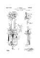
- Figure 1 is a vertical section through the liquid chambers or tanks showing in elevation the registration dials with the visible indications showin
- Fig. 2 is a vertlcal section on the line 22 of Fig. 1 in the direction of the arrows showingr the liquid chambers in elevation.
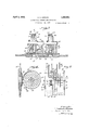
- ig. 3 is a horizontal section substantially on the line 3-3 of Fig. 1 through the dials and a shifting plate having exposure apertures.
- Fig. 4 is a vertical section on the line 4-4 of Figs. 1 or 3 in the direction of the arrows showing the registration device and the aperture plates.
- Fig. 5 is a partial view similar to Fig. 1 showing the floats and inlet valves in slightly different positions.
- a rotatable shaft is indicated by the numeral 11. This is presumed tobe connected to a registering device in connection with the vehicle; for instance, if the vehicle is an automobile, it may be connected to the speedometer or the wheels or transmission, so that the shaft may make one complete revolution in two units of distance, and it is presumed in a land vehicle that a half mile is sufiicient for a unit of distance. If the device is used on an aeroplane, the shaft 11 would be connected to an air speed indicator so that it may rotate in accordance with the distance traveled through the air, the number of rotations, in accordfound suitable.
- the shaft 11 would be connected to a device giving the rate of travel of the vessel through the water.
- the shaft 11 is intended to indicate some part driven by the movement of the vehicle, such as a speedom eter shaft or the equivalent.
- the shaft 11 has an arm 12 connected thereto with a brush 13, which brush is adapted to engage electrical contacts 14 so that an electric current may pass through the lead 15 to the ground 16.
- Each of the fixed contacts 14 is connected by an electric lead 16' to solenoids 17 and 18.
- the windings of these solenoids are connected to a grounded source of power by leads indicated at 1-9.
- the solenoids are suitably supported on a frame 20 and have an armature shaft 21 operating in the course of the aligned solenoids, whereby this armature may be shifted from one side two chambers are formed in the tank by means of a partition 28.
- the fuel supply to the engine of the vehicle or boilers is provided by a fuel pipe 29 which has branches leading to inlet valves 30 and 31. There are outlet valves 32 and 33 leading to the outlet receptacle 26.
- a bracket frame 34 is preferabl suitably mounted on the top 25 of the tan and has a transverse rock shaft 35, to which is connected a rocker arm 36.
- This arm has a pin and slot connection 37 to the armature 21, and there is a toggle spring 38 connected between the arm 36 and a lug 39 on the top 25.
- Oscillating levers 40. and 41 are rigidly connected to the rocker arm 36 and to each of these there is connected links 42 and 43, and depending from these links are valve rods 44- and 45 which pass downwardly through the top of the tank. Adjacent the lower end of these valve rods there are outlet valve plu s 46 and 47 which operate to close the there is a valve plug 52 and 53 which form a closure respectively with the inlet valves 30 and 31.
- the indicating mechanism involves the following features: A pair of floats 54 and 55 are located in each of the chambers, each havin a float rod 56 connected thereto, such rods aving a head 57 connected thereto. Links 58 are slidably mounted in said heads, the links bein preferably screw-threaded at the lower em? 59 and having adjusting nuts thereon. A cable 60 is connected to each of the links and attached to a reel 61 are indicating dials designated generally by the numerals 62 and 63.
- the indicators comprise discs 64, each rotatably mounted on a shaft 65 supported on suitable journal arms 66, these arms being at- Leeaoes tures 71 and 72 which are adapted to register with apertures 73 and 74 of the panel.
- the aperture plate also has a brake block 75 which is adapted to bear against a friction disc 76 secured to each of the dials.
- These dials are graduated with indicia 77 and in the instance shown such graduationis intended to indicate a certain number of miles per gallon of fuel as is the ordinary designation of the operation of a motor vehicle.
- a drop arm 78 which is illustrated as being attached by a collar 7 9 to the fixed shaft 65.
- This drop arm has a rock shaft 80 which has upper oscillating levers 81 and 82 connected by links 83 to the rock levers 40 and 41.
- a rock arm 84 is connected by a pin and slot connection 85 to the sliding aperture plate 70.
- uch valve has been previously closed in the following manner, referring to Fig. 5 showing the positions of the inlet valves and the floats shortly after the liquid has started to flow out of the chamber or receptacle 24. It is to be understood that the fuel is drawn oif comparatively slowly through the outlet in large quantities so that they fill up rapidly, the filling being at such a rate that no matter how uneconomically the engine or'boiler may operate, the receptacle which has been emptied is filled before the solenoids again function to trip the valves.
- the-fioat 55 is .Therefore on the risin gradually descending as the fuel is used, but the valve plug 53 maintains the valve 31 closed, the plug being held upwardly by its bracket 48 on the valve rod 45.
- the float 54 is illustrated as .engaging the head 50 connected to the valve plug 52 and thrusting'this upwardly into the position to close the valve 30.
- the valve stems 49 must be of sufficient length between .the heads '50 and the collar 51 to allow the valve to be thrust upwardly therethrough, as illustrated in Fig. 5.
- the indicating mechanism operates substantially as follows: Presumin'g, as above mentioned, that the solenoid 17 has just been energized, as shown in Fig. 1, the dial 62 gives the indication of the rate of consumption of the fuel during the depletionof the receptacle 23, in that the oscillating levers 81 and 82 have been shifted to the position shown in Fig. 1; and through the medium of the rock arm 84 the slidable-aperture plate has been shifted into the position shown in Figs. 1 and 3, thus exposing the'indicia 77 graduated in miles per gallon. In the present instance this indicates the figure 5 which is intended to indicate that the vehicle had been consuming fuel at the rate of 5 miles to a gallon of fuel. In this same'action the.
- the device is used on anaeroplane which must be continuously traveling through the air, when off the ground the rate of consumption of fuel will be in accordance with the units of distance traveled with relation to the motion through the air; and in such connection, if the aeroplane is a multi-engine type, there should be an indicator for each engine in order to show the economy of working of such engine. If the device is in a steam vessel or locomotive using steam, and liquid fuel, the device can be operated in connection with the total fuel supply, or where a number of boilers are used there may be an indicator for each boiler.
- the moving controlling device having the shaft 11, the arm 12 and the brush 13 engaging the contacts 14 can be driven by some other part of a moving mechanism than a part connected to a vehicle registering distance; and thus my fuel consumption indicator may be connected to stationary and other similar types of engines, and thus indicate their relative economy of in connection with the work done by suc engines.
- the controlling device may be interconnected with a timing mechanism operating by units of time, and thus designating the relative consumption of fuel inaccordance with the time factor. 1
- valves 46 and 47 may if desired be operated manually, in which case the driver of the vehicle may shift the rock arm 84 by hand and this will actuate the links 83 and hence reverse the valves. Such action may be done if the engine for instance is on an automobile or an aeroplane or running without the vehicle having any forward travel. It is obvious therefore that as no distance can be recorded, that the device would notindicate any number of units of distance per unit of fuel.
- a liquid fuel consumption indicator comprising in combination a movable control device adapted to be actuated by a moving part of a vehicle to indicate units of distance traveled, a plurality of liquid fuel receptacles each having a separate inlet and outlet controlled by the said device, a plurality. of indicators for the rate of consump- .tion of fuel, and means to actuate each of 2.
- a liquid fuel consumption indicator comprising in combination a controlling deinlets and outlets with the control device to actuate same in sequence, a float for each receptacle, and separate means actuated by each float to indicate the rate of consumption of fuel.
- a liquid fuel consumption indicator as claimed in claim 2, one of said indicating means of the rate of consumption of fuel being held stationary while the other indi cating means is registering a tally.
- each of the indicating means of the rate of consumption of fuel having an indicating dial actuated by a cable connected to one of the floats, and means to hold one of said dials stationary while the float connected to the other dial is following the outflow of the fuel and recording a tally.
- a liquid fuel consumption indicator comprising in'combination a moving device adapted to indicate units of distance traveled of a vehicle, a plurality of liquid fuel receptacles, each having a separate inlet and outlet, electro-magnetic means controlled by said device to operate said inlets and outlets 1n sequence, a plurality iof indicators to give .the rate of consumption of fuel, and means interconnecting each indicator and each fuel other indicator is held stationary.
- a liquid fuel consumption indicator as claimed in claim 5, the indicators comprising dials, each dial being connected by a cable to a float in one of the liquid fuel receptacles, one of the floats rising during the filling of the receptacle while the other float moves down during the discharge of its receptacle, and means to hold the indicator stationary which is connected to the upwardly moving float.
- a liquid fuel consumption indicator comprising in combination a plurality of liquid fuel receptacles, each having a separate inlet and outlet, means actuated by units of distance traveled of a vehicle to open the inlet and close the outlet of each receptacle in sequence, a float in each receptacle, said float on filling a receptacle closing an inlet valve before the other receptacle is emptied, and an indicating means actuated by said lgoalts showing the rate of consumption of 8.
- a liquid fuel consumption indicator as claimed in claim 7, the indicating means comprising a plurality of rotatable dials, each dial being interconnected to a float in a receptacle, one of said dials being held stationary while its float is rising and giving a visible indication, the other dial being rotatable while its float descends through consumption of the fuel.
- a liquid fuel consumption indicator comprising in combination a pair of liquid fuel receptacles, each having a separate inlet and outlet, a double action valve operating device to open each outlet alternately, floats in each receptacle adapted to close each inlet on the filling of a receptacle, means actuated by a unit of movement of a mechanism to control the double action valve operating de vice, and an indicating means interconnected with each of the floats to give an indication of the rate of consumption of fuel.
- a liquid fuel consumption indicator comprising in combination a plurality of dials having indicia thereon, a shiftable aperture plate having apertures therethrough to expose the indicia omone dial and shut off the other, a plurality of liquid fuel receptacles, means operated by the outflow of fuel from each receptacle to operate each dial in turn, an outlet valve for each receptacle, a double-acting trip device to open the valves alternately, said trip device shifting the aperture plate, means to flow fuel into said receptacles, and a control device governing the tr1p device.
- a liquid fuel consumption indicator comprising in combination a pair of dials each having indicia thereon, a shiftable aperture therethrough to expose and cover indicia on each dial alternately, a pair of receptacles having outlets, a float in each receptacle, means interconnecting each float and a dial to rotate the dial on a downward movement of the float, means to return each dial on the upward movement of the float, an inlet valve to each receptacle adapted to be closed by the floats, a double acting trip mechanism to open and close each of the outlets alternately and to permit opening of each of the inlet valves alternately and to shift the aperture plate, and a control device for said double acting trip mechanism.
- a liquid fuel consumption regulator comprising in combination a fuel supply means for a vehicle, a device actuated by the movement of the vehicle to control said fuel supply in relation to units of distance, a plurality of registers controlled by the fuel supply, each having indicia thereon, and means to expose the indicia on one of the registers and obscure the indicia on the other register while the other register is making a registration.
- a liquid fuel consumption indicator comprising a fuel supply for the engine of a vehicle, an electI'o-mechanical device actuated by a unit distance oftravel of the vehicle to control the fuel supply, a plurality of registers connected to the fuel supply, one of said registers being stationary and giving an indication while the other register is undergoing a registering operation.
- a liquid fuel consumption indicator comprising in combination means to supply liquid fuel to the engine of a vehicle, electromechanical means operated by the movement of the vehicle through a unit of distance and controlling the operation of the fuel supply, a plurality of registers connected to the fuel supply, having two sets of indicia and means to expose one set of indicia on one of the registers and obscure the indicia on the other register while the other register is undergoing a registering operation.
- a liquid fuel consumption indicator comprising in combination a plurality of liquid fuel receptacles having control valves to supply liquid fuel to the tanks and from the tanks to an engine, electro-mechanical means operated by the vehicle in a unit dis tance oftravel to operate the said valves, a plurality of registers, each being operatively connected to a liquid fuel receptacle to indicate the consumption of fuel therefrom, indicia on said registers and a shiftable obscuring means to expose the indicia of one register and obscure the indicia on the other register while the other register is undergoing a registering operation.
Landscapes
- Physics & Mathematics (AREA)
- Fluid Mechanics (AREA)
- General Physics & Mathematics (AREA)
- Level Indicators Using A Float (AREA)
Description
1927 2 Sheets-Sheet 1 s. 5 7 6 6 3 8 0 2 V 7 I w 6 r 5 fin I a 6 r J W 4 a i gt I] l 3 m 1 &
April 5, 1932. c. c. BROWN LIQUID FUEL CONSUMPTION INDICATOR Filed Nov. 30,
nnmum 14 I;
2 Sheets-Sheet 2 April 5, 1932. c.. c. BROWN LIQUID FUEL CONSUMPTION INDICATOR Filed Nov. 50. 1927 Patented Apr. 1932 UNITED STATES PATENT OFFICE Application med November 30, 1927. Serial No. 236,738.
My invention comprises a liquid fuel con sumption indicator. v
The invention of my present indicator, has for an object giving an indicdtion of the rate of using liquid fuel in accordance with dis- "tance traveled; The indicator may be calibrated to show a distance which may he traveled on a designatedunit of fuel at a certain rate of consumption, suchas so many miles travel to the gallon of fuel or bite meters to the liter of fuel, etc. Or the device may be calibrated to show the units of fuel usedin a unit of distance, as the number of gallons and fractions thereof used in a mile 5' travel, or the number of liters of fuel used in 'a kilometer-travel, etc. i
An object of my invention is an indicator which may be utilized with a number of different types of vehicles and give an indicaso 'tion of the rate at which fuel is being used to drive such vehicle. For instance, if the vehicle is an automobile, the indicator, as above mentioned, may show the number of miles er gallon, or kilometers per liter that I as could e traveled at any particular time in which the indicator is examined. The device may also be applied to aeroplanes and give a similar indication, but in this case it would be relative to'the air s eed. In this connection' the indicator won 6. show the number of air miles traveled on a gallon of fuel or kilometers on a liter of fuel, or the graduation could indicate the number of gallons or fractions used in traveling an air mile or the number'of liters used in traveling an air kilometer.
This .present invention operates on the proportion of the amount of fuel used per unit of distance, this being registered in any suitable terms for interpretation.
My application for a liquid fuel consumption indicator, Serial No. 236,739, operates by utilizing a unit quantity of fuel having the register operate in the relation of distance per unit of fuel.
The device may also be utilized on ships and connected to the engine's showing the consumptiolf of fuel in relation to the distance traveled by the ship through the water.
Inthe present invention-I employ a suitable mechanism connected with the operating part of a vehicle so that on a predetermined distance of travel either over the ground, through the air or in water, the device is actuated to give an indication which, as above mentioned, may be calibrated in the various manners set forth. For instance; the device may, at each mile or,half mile or other predetermined distance of travel, be actuated to give the indication, and such indications would probably be at sufficient intervals to allow the operator of a vehicle or the person in control of an engine to know if this were operating to the best advantage.
My liquid fuel consumption indicator may be utilized for internal combustion engines in which the explosive fuel passes through the indicator and operates same, or it may be utilized in connection with steam boilers which are fired by'a liquid fuel.
In the present construction I employ a pair of liquid fuel chambers, each having an inlet and an outlet controlled by separate valves. A trip mechanism, preferably electrically controlled on a predetermined distance of travel of the vehicle, is actuated to close the outlet valves of each chamber or compartment alternately, and at the same time to open one inlet valve, the other being closed.
a The fuel is designed to flow into the cham- 30 bers much faster than it can flow out, whereby a float in each chamber closes the inlet valve before the outlet valve for the other chamber is closed, it being understood that the outlet valve for. each chamber is closed while its inlet valve is open.
The floats in each chamber are connected to registering dials or the like and on the downward movement of each float, due to the consumption of fuel from the. particular chamber in operation, the dial is turned. The dial that is being moved, however, having' a gradual movement does not give the mediate registration; but this is done by a dial which is held stationary during the fill- 5 ing of the tank or chamber to which said stationary dial is connected by a float. -Thus at every predetermined unit of travel, an indication is given of the. rate of fuel consumption. While this does not give an ab 1 solutely continuously fluctuating registration, it is sufficient to determine the e ciency of operation of the propelling mechanism for the vehicle and to gauge the rate at which fuel is being used.
M invention will be more readily understoo from the following description and drawings, in which: I
Figure 1 is a vertical section through the liquid chambers or tanks showing in elevation the registration dials with the visible indications showin Fig. 2 is a vertlcal section on the line 22 of Fig. 1 in the direction of the arrows showingr the liquid chambers in elevation.
ig. 3 is a horizontal section substantially on the line 3-3 of Fig. 1 through the dials and a shifting plate having exposure apertures.
Fig. 4 is a vertical section on the line 4-4 of Figs. 1 or 3 in the direction of the arrows showing the registration device and the aperture plates.
Fig. 5 is a partial view similar to Fig. 1 showing the floats and inlet valves in slightly different positions.
Referring to Fig. 1 a rotatable shaft is indicated by the numeral 11. This is presumed tobe connected to a registering device in connection with the vehicle; for instance, if the vehicle is an automobile, it may be connected to the speedometer or the wheels or transmission, so that the shaft may make one complete revolution in two units of distance, and it is presumed in a land vehicle that a half mile is sufiicient for a unit of distance. If the device is used on an aeroplane, the shaft 11 would be connected to an air speed indicator so that it may rotate in accordance with the distance traveled through the air, the number of rotations, in accordfound suitable.
ance with distance, being such as may be If the device is used on a vessel, the shaft 11 would be connected to a device giving the rate of travel of the vessel through the water.
Considering the invention installed on a vehicle such as an automobile, the shaft 11 is intended to indicate some part driven by the movement of the vehicle, such as a speedom eter shaft or the equivalent.
The shaft 11 has an arm 12 connected thereto with a brush 13, which brush is adapted to engage electrical contacts 14 so that an electric current may pass through the lead 15 to the ground 16. Each of the fixed contacts 14 is connected by an electric lead 16' to solenoids 17 and 18. The windings of these solenoids are connected to a grounded source of power by leads indicated at 1-9. The solenoids are suitably supported on a frame 20 and have an armature shaft 21 operating in the course of the aligned solenoids, whereby this armature may be shifted from one side two chambers are formed in the tank by means of a partition 28.
The fuel supply to the engine of the vehicle or boilers is provided by a fuel pipe 29 which has branches leading to inlet valves 30 and 31. There are outlet valves 32 and 33 leading to the outlet receptacle 26.
These valves are mechanically controlled in the following manner: A bracket frame 34 is preferabl suitably mounted on the top 25 of the tan and has a transverse rock shaft 35, to which is connected a rocker arm 36. This arm has a pin and slot connection 37 to the armature 21, and there is a toggle spring 38 connected between the arm 36 and a lug 39 on the top 25.
Oscillating levers 40. and 41 are rigidly connected to the rocker arm 36 and to each of these there is connected links 42 and 43, and depending from these links are valve rods 44- and 45 which pass downwardly through the top of the tank. Adjacent the lower end of these valve rods there are outlet valve plu s 46 and 47 which operate to close the there is a valve plug 52 and 53 which form a closure respectively with the inlet valves 30 and 31.
The indicating mechanism involves the following features: A pair of floats 54 and 55 are located in each of the chambers, each havin a float rod 56 connected thereto, such rods aving a head 57 connected thereto. Links 58 are slidably mounted in said heads, the links bein preferably screw-threaded at the lower em? 59 and having adjusting nuts thereon. A cable 60 is connected to each of the links and attached to a reel 61 are indicating dials designated generally by the numerals 62 and 63.
The indicators comprise discs 64, each rotatably mounted on a shaft 65 supported on suitable journal arms 66, these arms being at- Leeaoes tures 71 and 72 which are adapted to register with apertures 73 and 74 of the panel. The aperture plate also has a brake block 75 which is adapted to bear against a friction disc 76 secured to each of the dials. These dials are graduated with indicia 77 and in the instance shown such graduationis intended to indicate a certain number of miles per gallon of fuel as is the ordinary designation of the operation of a motor vehicle.
Depending from the structure carrying the dials there is a drop arm 78 which is illustrated as being attached by a collar 7 9 to the fixed shaft 65. This drop arm has a rock shaft 80 which has upper oscillating levers 81 and 82 connected by links 83 to the rock levers 40 and 41. A rock arm 84 is connected by a pin and slot connection 85 to the sliding aperture plate 70.
The manner of operation of my liquid fuel indicator is substantiall as follows: In the ,mechanism as positione in Fig. 1 1t presumed that the brush 13 has just made a con tact with the fixed contact 14, the arm-12 being presumed toirotate in a clockwise direction. The solenoid 17 has therefore just been energized and has shifted the armature 21, thereby rocking the arm 36 to the position illustrated. This action, through the medium of the rock lever 40 and 41 actuates the valve rods 44 and 45, thrusting the valve plug 46 into a position closing the valve 32 and rais ing the valve plug'47, thus opening the valve 33. At the sameitime the bracket 48 on the rod 44 has moved downwardly, thereby allowing the valve plug 52 to open the valve 30, the
collar 51 resting on the bracket 48; also at the same time, the bracket 48 on the other valve rod 'has been moved upwardly and engages underneath the collar 51 of the stem 49 having the valve plug 53, thus maintaininthe valve 31 closed. L
uch valve has been previously closed in the following manner, referring to Fig. 5 showing the positions of the inlet valves and the floats shortly after the liquid has started to flow out of the chamber or receptacle 24. It is to be understood that the fuel is drawn oif comparatively slowly through the outlet in large quantities so that they fill up rapidly, the filling being at such a rate that no matter how uneconomically the engine or'boiler may operate, the receptacle which has been emptied is filled before the solenoids again function to trip the valves.
Hence, as shown inFig. 5, the-fioat 55 is .Therefore on the risin gradually descending as the fuel is used, but the valve plug 53 maintains the valve 31 closed, the plug being held upwardly by its bracket 48 on the valve rod 45. As the receptacle which has been depleted is filled rapidly, the float 54 is illustrated as .engaging the head 50 connected to the valve plug 52 and thrusting'this upwardly into the position to close the valve 30. To accommodate this action the valve stems 49 must be of sufficient length between .the heads '50 and the collar 51 to allow the valve to be thrust upwardly therethrough, as illustrated in Fig. 5.
From the above description it will be seen that as soon asthe receptacle fills its inlet valve is closed, and when the oscillating levers 40 and 41 are swung over into the opposite position, the inlet valve of the' receptacle filled is maintained closed.
The indicating mechanism operates substantially as follows: Presumin'g, as above mentioned, that the solenoid 17 has just been energized, as shown in Fig. 1, the dial 62 gives the indication of the rate of consumption of the fuel during the depletionof the receptacle 23, in that the oscillating levers 81 and 82 have been shifted to the position shown in Fig. 1; and through the medium of the rock arm 84 the slidable-aperture plate has been shifted into the position shown in Figs. 1 and 3, thus exposing the'indicia 77 graduated in miles per gallon. In the present instance this indicates the figure 5 which is intended to indicate that the vehicle had been consuming fuel at the rate of 5 miles to a gallon of fuel. In this same'action the. brake block is brought to bear against the brake disc 76 on the dial 62 and holds this stationary. movement of the float 54, the head 57 sli es upwardly on the link 58 slidable therethrough as illustrated in Fig. 5, but this figure or indicia 77 remains exposed until the next action of the device.
While the receptacle 24 is being emptied, the float 55 moves downwardly and as the brake block 75 has been shifted from stopping the dial 63, this dial is returned to the initial position by the spring 68, and is in this initial position before the float 55 starts its downward movement. Such downward movement rotates the dial by pulling downwardly on the cable 60 and thereby causes the dial to turn, which dial has indicia similar to those indicated at 77; and when the solenoids are again energized to shift the valves and the slidable aperature plate, the dial 63 will be brought to rest and the indicia marked thereon will be exposed through the apertures 72 and 74, thus giving a reading showing the rate of consumption of fuel during the depletion of the receptacle 24.
The above action continues in the above cycles so long as the vehicle is traveling for if the shaft 11 is connected to a part of the vehicle registering movement over the ground the device does not indicate the consumption of fuel when the vehicle is stationary. How- 'workin ever, if the unit distances are made sufficiently small and the calibration of the dials made accordingly, frequent indications of the rate of the consumption of fuel may be given which are sufficient for all practical purposes.
It will be apparent that if the device is used on anaeroplane which must be continuously traveling through the air, when off the ground the rate of consumption of fuel will be in accordance with the units of distance traveled with relation to the motion through the air; and in such connection, if the aeroplane is a multi-engine type, there should be an indicator for each engine in order to show the economy of working of such engine. If the device is in a steam vessel or locomotive using steam, and liquid fuel, the device can be operated in connection with the total fuel supply, or where a number of boilers are used there may be an indicator for each boiler.
It is obvious that the moving controlling device having the shaft 11, the arm 12 and the brush 13 engaging the contacts 14 can be driven by some other part of a moving mechanism than a part connected to a vehicle registering distance; and thus my fuel consumption indicator may be connected to stationary and other similar types of engines, and thus indicate their relative economy of in connection with the work done by suc engines. Or if desired the controlling device may be interconnected with a timing mechanism operating by units of time, and thus designating the relative consumption of fuel inaccordance with the time factor. 1
From the above description it will be seen that I have not only developed a mechanism for indicating the consumption of liquid fuel but I have developed a method of indicating fuel consumption in which, through the medium of a controlling device indicating distance of travel, amount of movement of a certain mechanism, or a time unit, an indication is obtained of the flow of liquid fuel out of a receptacle or tank, thus giving the indication desired. Or, expressed another way, the inflow and outflow of liquid fuel to-receptacles or tanks is governed by a controlling device ,which may be operated to indicate distance of travel and the outflow of fuel from the receptacle or tank indicates on a registering mechanism the rate of consumption of such fuel.
The valves 46 and 47 may if desired be operated manually, in which case the driver of the vehicle may shift the rock arm 84 by hand and this will actuate the links 83 and hence reverse the valves. Such action may be done if the engine for instance is on an automobile or an aeroplane or running without the vehicle having any forward travel. It is obvious therefore that as no distance can be recorded, that the device would notindicate any number of units of distance per unit of fuel.
In the claims where reference is made to the relation between the units of fuel and the units of distance, this is intended to refer to the case in which the engine consuming the fuel is on a vehicle and such vehicle is travel- I ariOus changes may be made in the principles of my invention without departing from the spirit thereof, as set forth in the description, drawings and claims.
I claim:
1. A liquid fuel consumption indicator comprising in combination a movable control device adapted to be actuated by a moving part of a vehicle to indicate units of distance traveled, a plurality of liquid fuel receptacles each having a separate inlet and outlet controlled by the said device, a plurality. of indicators for the rate of consump- .tion of fuel, and means to actuate each of 2. A liquid fuel consumption indicator comprising in combination a controlling deinlets and outlets with the control device to actuate same in sequence, a float for each receptacle, and separate means actuated by each float to indicate the rate of consumption of fuel.
3. A liquid fuel consumption indicator, as claimed in claim 2, one of said indicating means of the rate of consumption of fuel being held stationary while the other indi cating means is registering a tally.
4:. A liquid fuel consumption indicator, as claimed in claim 2, each of the indicating means of the rate of consumption of fuel having an indicating dial actuated by a cable connected to one of the floats, and means to hold one of said dials stationary while the float connected to the other dial is following the outflow of the fuel and recording a tally.
5. A liquid fuel consumption indicator comprising in'combination a moving device adapted to indicate units of distance traveled of a vehicle, a plurality of liquid fuel receptacles, each having a separate inlet and outlet, electro-magnetic means controlled by said device to operate said inlets and outlets 1n sequence, a plurality iof indicators to give .the rate of consumption of fuel, and means interconnecting each indicator and each fuel other indicator is held stationary.
6. A liquid fuel consumption indicator, as claimed in claim 5, the indicators comprising dials, each dial being connected by a cable to a float in one of the liquid fuel receptacles, one of the floats rising during the filling of the receptacle while the other float moves down during the discharge of its receptacle, and means to hold the indicator stationary which is connected to the upwardly moving float.
7. A liquid fuel consumption indicator comprising in combination a plurality of liquid fuel receptacles, each having a separate inlet and outlet, means actuated by units of distance traveled of a vehicle to open the inlet and close the outlet of each receptacle in sequence, a float in each receptacle, said float on filling a receptacle closing an inlet valve before the other receptacle is emptied, and an indicating means actuated by said lgoalts showing the rate of consumption of 8. A liquid fuel consumption indicator, as claimed in claim 7, the indicating means comprising a plurality of rotatable dials, each dial being interconnected to a float in a receptacle, one of said dials being held stationary while its float is rising and giving a visible indication, the other dial being rotatable while its float descends through consumption of the fuel.
9. A liquid fuel consumption indicator comprising in combination a pair of liquid fuel receptacles, each having a separate inlet and outlet, a double action valve operating device to open each outlet alternately, floats in each receptacle adapted to close each inlet on the filling of a receptacle, means actuated by a unit of movement of a mechanism to control the double action valve operating de vice, and an indicating means interconnected with each of the floats to give an indication of the rate of consumption of fuel.
10. A liquid fuel consumption indicator comprising in combination a plurality of dials having indicia thereon, a shiftable aperture plate having apertures therethrough to expose the indicia omone dial and shut off the other, a plurality of liquid fuel receptacles, means operated by the outflow of fuel from each receptacle to operate each dial in turn, an outlet valve for each receptacle, a double-acting trip device to open the valves alternately, said trip device shifting the aperture plate, means to flow fuel into said receptacles, and a control device governing the tr1p device.
11. A liquid fuel consumption indicator comprising in combination a pair of dials each having indicia thereon, a shiftable aperture therethrough to expose and cover indicia on each dial alternately, a pair of receptacles having outlets, a float in each receptacle, means interconnecting each float and a dial to rotate the dial on a downward movement of the float, means to return each dial on the upward movement of the float, an inlet valve to each receptacle adapted to be closed by the floats, a double acting trip mechanism to open and close each of the outlets alternately and to permit opening of each of the inlet valves alternately and to shift the aperture plate, and a control device for said double acting trip mechanism.
12. A liquid fuel consumption regulator comprising in combination a fuel supply means for a vehicle, a device actuated by the movement of the vehicle to control said fuel supply in relation to units of distance, a plurality of registers controlled by the fuel supply, each having indicia thereon, and means to expose the indicia on one of the registers and obscure the indicia on the other register while the other register is making a registration.
13. A liquid fuel consumption indicator comprising a fuel supply for the engine of a vehicle, an electI'o-mechanical device actuated by a unit distance oftravel of the vehicle to control the fuel supply, a plurality of registers connected to the fuel supply, one of said registers being stationary and giving an indication while the other register is undergoing a registering operation.
14:. A liquid fuel consumption indicator comprising in combination means to supply liquid fuel to the engine of a vehicle, electromechanical means operated by the movement of the vehicle through a unit of distance and controlling the operation of the fuel supply, a plurality of registers connected to the fuel supply, having two sets of indicia and means to expose one set of indicia on one of the registers and obscure the indicia on the other register while the other register is undergoing a registering operation.
15. A liquid fuel consumption indicator comprising in combination a plurality of liquid fuel receptacles having control valves to supply liquid fuel to the tanks and from the tanks to an engine, electro-mechanical means operated by the vehicle in a unit dis tance oftravel to operate the said valves, a plurality of registers, each being operatively connected to a liquid fuel receptacle to indicate the consumption of fuel therefrom, indicia on said registers and a shiftable obscuring means to expose the indicia of one register and obscure the indicia on the other register while the other register is undergoing a registering operation.
In testimonywhereof I have signed my name to this specification.
' CLAUDE 0. BROWN.
Priority Applications (1)
| Application Number | Priority Date | Filing Date | Title |
|---|---|---|---|
| US236738A US1852553A (en) | 1927-11-30 | 1927-11-30 | Liquid fuel consumption indicator |
Applications Claiming Priority (1)
| Application Number | Priority Date | Filing Date | Title |
|---|---|---|---|
| US236738A US1852553A (en) | 1927-11-30 | 1927-11-30 | Liquid fuel consumption indicator |
Publications (1)
| Publication Number | Publication Date |
|---|---|
| US1852553A true US1852553A (en) | 1932-04-05 |
Family
ID=22890743
Family Applications (1)
| Application Number | Title | Priority Date | Filing Date |
|---|---|---|---|
| US236738A Expired - Lifetime US1852553A (en) | 1927-11-30 | 1927-11-30 | Liquid fuel consumption indicator |
Country Status (1)
| Country | Link |
|---|---|
| US (1) | US1852553A (en) |
-
1927
- 1927-11-30 US US236738A patent/US1852553A/en not_active Expired - Lifetime
Similar Documents
| Publication | Publication Date | Title |
|---|---|---|
| US1852553A (en) | Liquid fuel consumption indicator | |
| US1576445A (en) | Instrument or apparatus for indicating the flow or consumption of liquids such as liquid fuel | |
| US1401315A (en) | Meter | |
| DE831610C (en) | Device for measuring the amount of a liquid flowing in a pipe | |
| US1477490A (en) | Miles-per-gallon instrument | |
| US1595960A (en) | Efficiency indicator for automotive vehicles | |
| US1723173A (en) | Means for measuring the quantity of liquid in tanks | |
| US1454301A (en) | Fluid meter | |
| US2147500A (en) | Hydrometer attachment for motor propelled vehicles | |
| US2866331A (en) | Flow measuring and signalling mechanism | |
| US2196285A (en) | Fluid flow measuring device | |
| US1552119A (en) | Fuel-consumption indicator | |
| US1479873A (en) | Flow meter | |
| US1654421A (en) | Mileage meter | |
| US1746133A (en) | Motor-efficiency indicator | |
| US1592707A (en) | Liquid meter | |
| US1527114A (en) | Combined fuel-consumption and speed indicator | |
| US1440353A (en) | Registering device | |
| US1253324A (en) | Indicating apparatus for gasolene-tanks, &c. | |
| US2216737A (en) | Rate indicator | |
| US1515988A (en) | Integrating and registering device for fluid meters | |
| US1235200A (en) | Meter. | |
| US1489060A (en) | Indicator for motor vehicles | |
| US1491777A (en) | Meter | |
| US1503552A (en) | Miles-per-gallon register |