US1852536A - Drive-chain - Google Patents
Drive-chain Download PDFInfo
- Publication number
- US1852536A US1852536A US300169A US30016928A US1852536A US 1852536 A US1852536 A US 1852536A US 300169 A US300169 A US 300169A US 30016928 A US30016928 A US 30016928A US 1852536 A US1852536 A US 1852536A
- Authority
- US
- United States
- Prior art keywords
- chain
- pintle
- link plates
- parts
- plates
- Prior art date
- Legal status (The legal status is an assumption and is not a legal conclusion. Google has not performed a legal analysis and makes no representation as to the accuracy of the status listed.)
- Expired - Lifetime
Links
- 230000005540 biological transmission Effects 0.000 description 3
- 239000002184 metal Substances 0.000 description 2
- 230000004048 modification Effects 0.000 description 1
- 238000012986 modification Methods 0.000 description 1
Images
Classifications
-
- F—MECHANICAL ENGINEERING; LIGHTING; HEATING; WEAPONS; BLASTING
- F16—ENGINEERING ELEMENTS AND UNITS; GENERAL MEASURES FOR PRODUCING AND MAINTAINING EFFECTIVE FUNCTIONING OF MACHINES OR INSTALLATIONS; THERMAL INSULATION IN GENERAL
- F16G—BELTS, CABLES, OR ROPES, PREDOMINANTLY USED FOR DRIVING PURPOSES; CHAINS; FITTINGS PREDOMINANTLY USED THEREFOR
- F16G13/00—Chains
- F16G13/02—Driving-chains
- F16G13/06—Driving-chains with links connected by parallel driving-pins with or without rollers so called open links
Definitions
- This invention relates to chains used in the transmission of power, and particularly to an improved chain in which the link plates are prevented from slipping or riding over the ends oi the bushings or pintle parts of i the chain.
- a common form of failure in chains is due to a pinching or crushing oi some of the pintle parts at their ends where side link plates bear upon them. The side links then tend to slip oil the end and jam between the pintle and another side link plate, or between link plate and washer.
- the primary object of the present invention is the provision of a chain in which such difliculties are overcome.
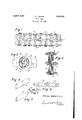
- Fig. l is a plan view showing by way of example the improvement as applied to a multi-strand chain.
- Fig. 2 is an enlarged cross-section on the line A-A of Fig. 1.
- Fig. 3 is a plan view with the pintle parts in elevation and the link plates and washers in cross-section, showing how the pintle parts are extended thru and beyond the side link plates.
- Fig. 4. is a perspective view illustrating one of the pintle parts.
- Fig. 5 is a perspective view illustrating another pintle part.
- Fig. 6 illustrates a modification
- Fig. 7 is a fragmentary plan section taken on the line 7-7 of Fig. 6.
- the chain is composed of link plates 7, 7 and pintle parts 8, 8, and 9, which extend across the chain thru holes in the link plates 7, '7 and may be engaged by sprocket teeth in the usual manner.
- a three part pintle is used, including a convex central member 9, shown in detail in Fig. 5, and a pair of concave bushing plates 8, 8 cooperating therewith.
- Various other forms of joint however might be used.
- the invention is also applicable to chains of the form in which the link plates extend for the full width of the chain and are provided with sprocket engaging teeth.
- the outside washers or plates 12 or 12 are dished or bent over to hold the chain together, while allowing room for the ends of the pintle parts.
- One of the pintle parts as for example the central member 9 in Fig. 3, or one of the bushing plates 8 or 8 in Fig. 6, is extended thru the washer 12 or side plate 12 and riveted thereto, thus holding the chain parts securely in place.
- the link plates 7 7 may be keyed into the pintle parts 8, 8 by projections 14 as shown in Fig. 2 or by other suitable means.
Landscapes
- Engineering & Computer Science (AREA)
- General Engineering & Computer Science (AREA)
- Mechanical Engineering (AREA)
- Devices For Conveying Motion By Means Of Endless Flexible Members (AREA)
Description
April 5, 1932. F. L. MORSE DRIVE CHAIN Filed Aug. 17, 1928 FRAMLMRSZ' R BY W/fv M ATTORNEYIZ Patented Apr. 5, 1932 UNITED STATES FRANK L. MORSE, F ITI-IAOA, NEW YORK,
ASESIGNOH TO MORSE OI-IAI NCOMP ANY, OF
ITHAGA, NEW YORK, A CORPORATION OF NEW 'YORK DRIVE-CHAIN Application filed. August 17, 1928. Serial No. 300,169.
This invention relates to chains used in the transmission of power, and particularly to an improved chain in which the link plates are prevented from slipping or riding over the ends oi the bushings or pintle parts of i the chain. A common form of failure in chains is due to a pinching or crushing oi some of the pintle parts at their ends where side link plates bear upon them. The side links then tend to slip oil the end and jam between the pintle and another side link plate, or between link plate and washer.
The primary object of the present invention is the provision of a chain in which such difliculties are overcome.
How the foregoing, together with such other objects as may hereinafter appear, or are incident to my invention, are realized, is illustrated in the accompanying drawings,
wherein Fig. l is a plan view showing by way of example the improvement as applied to a multi-strand chain.
Fig. 2 is an enlarged cross-section on the line A-A of Fig. 1.
Fig. 3 is a plan view with the pintle parts in elevation and the link plates and washers in cross-section, showing how the pintle parts are extended thru and beyond the side link plates.
Fig. 4. is a perspective view illustrating one of the pintle parts.
Fig. 5 is a perspective view illustrating another pintle part.
Fig. 6 illustrates a modification.
Fig. 7 is a fragmentary plan section taken on the line 7-7 of Fig. 6.
Referring now to Figs. 1, 2 and 3, the chain is composed of link plates 7, 7 and pintle parts 8, 8, and 9, which extend across the chain thru holes in the link plates 7, '7 and may be engaged by sprocket teeth in the usual manner. In the chain selected by way of illustration a three part pintle is used, including a convex central member 9, shown in detail in Fig. 5, and a pair of concave bushing plates 8, 8 cooperating therewith. Various other forms of joint however might be used. The invention is also applicable to chains of the form in which the link plates extend for the full width of the chain and are provided with sprocket engaging teeth.
It has not been uncommon in various forms of chains for the link plates at the outside ends of the bushings to work off the ends of the bushing, orwedge and crush the metal at the ends of the bushings. To overcome this ditliculty I have extended the pintle parts 8, 8, 9 not only entirely thru the outside link plates 7, but a substantial distance beyond, as clearly indicated in Fig. 3 by the reference numeral 10. When the chain is under tension the pressure of the side link plates 7 upon the pintle parts 8, 8 does not fall on the extreme ends of the pintle parts, but comes a sufiicient distance in so that there is no tendency for them to ride off. This strengthens the chain considerably, asthe point of application of the load is sufliciently far in so that the metal of the pintle part is well supported.
In order to permit this extension of the pintle parts the outside washers or plates 12 or 12 are dished or bent over to hold the chain together, while allowing room for the ends of the pintle parts. One of the pintle parts, as for example the central member 9 in Fig. 3, or one of the bushing plates 8 or 8 in Fig. 6, is extended thru the washer 12 or side plate 12 and riveted thereto, thus holding the chain parts securely in place. The link plates 7 7 may be keyed into the pintle parts 8, 8 by projections 14 as shown in Fig. 2 or by other suitable means. While I have in the foregoing shown the improvement applied to a ladder chain of the three part pintle type, the invention is also applicable to sin gle strand chains, as well as to chains of two, three or more strands, and also to two part pintles, and pintles of various other types, as will be apparent to those skilled in the art.
What I claim is:
1. In a power transmission chain of the silent type, the combination of side link plates, multi part pintles the parts of which extend through and beyond theouter side link plates, and dished side members for retaining the link plates and pintle parts in operative association, said extended portions of the pintle parts extending into the dished side members and providing support for the outside link plates as said plates move lengthwise of the pintles in service.
2. In a power transmission chain of the silent type, the combination of link plates, multi-part pintles for joining the link plates, said pintles being of a length substantially exceeding the width of the chain bounded by the link plates and cupped washers carried by one part of each pintle for retaining the link plates and pintleparts in operativeassociation, the other parts ofcsaid pintles-iextending into the cupped washers and said extending portions providing support for the -outside link plates of thechain as said plates move lengthwise of the pintles in service. i
3- ,A dr v he eeemp i gi -c mbine- 111011, ie 0 ink q lp jse f {Plates m -p r ri f joinin th nl nks, t parts of saidvpintles being substantially longer than the width, of thepchain from. one outside link plate to the opposite outside link plate so that substantial portions ofthe pintle parts, extend beyond the outside link plates ateach sideo'f the chain and dished side members into which saidportions extend for retaining the link plates and pintle parts in operative association, said portions providing support for the outsidelink plates as said plates jmove lengthwise of the pintles in service.
In testimony whereof have hereunto signed my name.
' FR NK
Priority Applications (1)
| Application Number | Priority Date | Filing Date | Title |
|---|---|---|---|
| US300169A US1852536A (en) | 1928-08-17 | 1928-08-17 | Drive-chain |
Applications Claiming Priority (1)
| Application Number | Priority Date | Filing Date | Title |
|---|---|---|---|
| US300169A US1852536A (en) | 1928-08-17 | 1928-08-17 | Drive-chain |
Publications (1)
| Publication Number | Publication Date |
|---|---|
| US1852536A true US1852536A (en) | 1932-04-05 |
Family
ID=23158000
Family Applications (1)
| Application Number | Title | Priority Date | Filing Date |
|---|---|---|---|
| US300169A Expired - Lifetime US1852536A (en) | 1928-08-17 | 1928-08-17 | Drive-chain |
Country Status (1)
| Country | Link |
|---|---|
| US (1) | US1852536A (en) |
-
1928
- 1928-08-17 US US300169A patent/US1852536A/en not_active Expired - Lifetime
Similar Documents
| Publication | Publication Date | Title |
|---|---|---|
| US2602344A (en) | Guide link for silent chains | |
| US1868334A (en) | Drive chain | |
| US2059063A (en) | Conveyer | |
| US3089346A (en) | Side bar link chain | |
| US2279134A (en) | Chain | |
| US1852536A (en) | Drive-chain | |
| US2047833A (en) | Power transmission chain | |
| US1952885A (en) | Interlocking silent chain | |
| US2860520A (en) | Chain conveyor | |
| US1734688A (en) | Multiple-drive chain | |
| US1517346A (en) | Chain and shackle | |
| US1586857A (en) | Chain | |
| US1644656A (en) | Power-transmission chain | |
| US2159396A (en) | Conveyer chain | |
| US1046124A (en) | Drive-chain. | |
| US1658602A (en) | Chain | |
| US2589887A (en) | Yieldable chain link | |
| US528622A (en) | William benjamin teale | |
| US1951764A (en) | Drive chain | |
| US1825675A (en) | Power transmission chain | |
| US2226755A (en) | Connecting link | |
| US1685112A (en) | Attachment for chains | |
| US1624111A (en) | Heavy-tension lap-link chain | |
| US1834173A (en) | Chain link | |
| US1878797A (en) | Link belt |