US1852534A - Sheet metal cutting machine - Google Patents
Sheet metal cutting machine Download PDFInfo
- Publication number
- US1852534A US1852534A US395292A US39529229A US1852534A US 1852534 A US1852534 A US 1852534A US 395292 A US395292 A US 395292A US 39529229 A US39529229 A US 39529229A US 1852534 A US1852534 A US 1852534A
- Authority
- US
- United States
- Prior art keywords
- gauge
- arms
- work
- piece
- rock shaft
- Prior art date
- Legal status (The legal status is an assumption and is not a legal conclusion. Google has not performed a legal analysis and makes no representation as to the accuracy of the status listed.)
- Expired - Lifetime
Links
- 238000005520 cutting process Methods 0.000 title description 46
- 239000002184 metal Substances 0.000 title description 12
- 239000011435 rock Substances 0.000 description 44
- 208000028659 discharge Diseases 0.000 description 12
- 238000010008 shearing Methods 0.000 description 8
- 238000005266 casting Methods 0.000 description 5
- YNPNZTXNASCQKK-UHFFFAOYSA-N Phenanthrene Natural products C1=CC=C2C3=CC=CC=C3C=CC2=C1 YNPNZTXNASCQKK-UHFFFAOYSA-N 0.000 description 1
- DGEZNRSVGBDHLK-UHFFFAOYSA-N [1,10]phenanthroline Chemical compound C1=CN=C2C3=NC=CC=C3C=CC2=C1 DGEZNRSVGBDHLK-UHFFFAOYSA-N 0.000 description 1
- 229940000425 combination drug Drugs 0.000 description 1
- 238000010276 construction Methods 0.000 description 1
- 230000005484 gravity Effects 0.000 description 1
- 238000004519 manufacturing process Methods 0.000 description 1
- 229920000136 polysorbate Polymers 0.000 description 1
- 239000002699 waste material Substances 0.000 description 1
Images
Classifications
-
- B—PERFORMING OPERATIONS; TRANSPORTING
- B23—MACHINE TOOLS; METAL-WORKING NOT OTHERWISE PROVIDED FOR
- B23D—PLANING; SLOTTING; SHEARING; BROACHING; SAWING; FILING; SCRAPING; LIKE OPERATIONS FOR WORKING METAL BY REMOVING MATERIAL, NOT OTHERWISE PROVIDED FOR
- B23D33/00—Accessories for shearing machines or shearing devices
- B23D33/02—Arrangements for holding, guiding, and/or feeding work during the operation
- B23D33/025—Guillotines with holding means behind the knives
-
- Y—GENERAL TAGGING OF NEW TECHNOLOGICAL DEVELOPMENTS; GENERAL TAGGING OF CROSS-SECTIONAL TECHNOLOGIES SPANNING OVER SEVERAL SECTIONS OF THE IPC; TECHNICAL SUBJECTS COVERED BY FORMER USPC CROSS-REFERENCE ART COLLECTIONS [XRACs] AND DIGESTS
- Y10—TECHNICAL SUBJECTS COVERED BY FORMER USPC
- Y10T—TECHNICAL SUBJECTS COVERED BY FORMER US CLASSIFICATION
- Y10T83/00—Cutting
- Y10T83/202—With product handling means
- Y10T83/2074—Including means to divert one portion of product from another
- Y10T83/2083—Deflecting guide
-
- Y—GENERAL TAGGING OF NEW TECHNOLOGICAL DEVELOPMENTS; GENERAL TAGGING OF CROSS-SECTIONAL TECHNOLOGIES SPANNING OVER SEVERAL SECTIONS OF THE IPC; TECHNICAL SUBJECTS COVERED BY FORMER USPC CROSS-REFERENCE ART COLLECTIONS [XRACs] AND DIGESTS
- Y10—TECHNICAL SUBJECTS COVERED BY FORMER USPC
- Y10T—TECHNICAL SUBJECTS COVERED BY FORMER US CLASSIFICATION
- Y10T83/00—Cutting
- Y10T83/202—With product handling means
- Y10T83/2092—Means to move, guide, or permit free fall or flight of product
- Y10T83/2198—Tiltable or withdrawable support
-
- Y—GENERAL TAGGING OF NEW TECHNOLOGICAL DEVELOPMENTS; GENERAL TAGGING OF CROSS-SECTIONAL TECHNOLOGIES SPANNING OVER SEVERAL SECTIONS OF THE IPC; TECHNICAL SUBJECTS COVERED BY FORMER USPC CROSS-REFERENCE ART COLLECTIONS [XRACs] AND DIGESTS
- Y10—TECHNICAL SUBJECTS COVERED BY FORMER USPC
- Y10T—TECHNICAL SUBJECTS COVERED BY FORMER US CLASSIFICATION
- Y10T83/00—Cutting
- Y10T83/566—Interrelated tool actuating means and means to actuate work immobilizer
- Y10T83/5669—Work clamp
- Y10T83/576—Clamp actuating means driven by tool or tool support
- Y10T83/5769—Clamp yieldably driven by tool or tool support
- Y10T83/5778—With resilient drive element
-
- Y—GENERAL TAGGING OF NEW TECHNOLOGICAL DEVELOPMENTS; GENERAL TAGGING OF CROSS-SECTIONAL TECHNOLOGIES SPANNING OVER SEVERAL SECTIONS OF THE IPC; TECHNICAL SUBJECTS COVERED BY FORMER USPC CROSS-REFERENCE ART COLLECTIONS [XRACs] AND DIGESTS
- Y10—TECHNICAL SUBJECTS COVERED BY FORMER USPC
- Y10T—TECHNICAL SUBJECTS COVERED BY FORMER US CLASSIFICATION
- Y10T83/00—Cutting
- Y10T83/727—With means to guide moving work
- Y10T83/744—Plural guide elements
-
- Y—GENERAL TAGGING OF NEW TECHNOLOGICAL DEVELOPMENTS; GENERAL TAGGING OF CROSS-SECTIONAL TECHNOLOGIES SPANNING OVER SEVERAL SECTIONS OF THE IPC; TECHNICAL SUBJECTS COVERED BY FORMER USPC CROSS-REFERENCE ART COLLECTIONS [XRACs] AND DIGESTS
- Y10—TECHNICAL SUBJECTS COVERED BY FORMER USPC
- Y10T—TECHNICAL SUBJECTS COVERED BY FORMER US CLASSIFICATION
- Y10T83/00—Cutting
- Y10T83/727—With means to guide moving work
- Y10T83/747—Opposed to work-supporting surface
-
- Y—GENERAL TAGGING OF NEW TECHNOLOGICAL DEVELOPMENTS; GENERAL TAGGING OF CROSS-SECTIONAL TECHNOLOGIES SPANNING OVER SEVERAL SECTIONS OF THE IPC; TECHNICAL SUBJECTS COVERED BY FORMER USPC CROSS-REFERENCE ART COLLECTIONS [XRACs] AND DIGESTS
- Y10—TECHNICAL SUBJECTS COVERED BY FORMER USPC
- Y10T—TECHNICAL SUBJECTS COVERED BY FORMER US CLASSIFICATION
- Y10T83/00—Cutting
- Y10T83/748—With work immobilizer
- Y10T83/7593—Work-stop abutment
- Y10T83/7647—Adjustable
Definitions
- My present invention relates to sheet metal work machines and more particularly shearing machines and has for its object the provision of a simple and highly eflicient supporting, gauginn', and releasing, mechanism therefor, and to such ends the invention cons sts of the novel devices and combi nation of devices hereinafter described and defined in the claims.
- Fig. 1 is a perspective rear view of a shear lug machine having; the invention embodied therein;
- Fig. 2 is a plan view of the same
- Fig. 3 is a fragmentary perspective front view of the shearing machine, on a reduced o scale
- Fig. 4 is a fragmentary detail view principally in section taken on the line 4% of Fig. 1, with some parts shown in different positions by broken lines;
- Fig. 5 is a fragmentary view principally in rear ekwation with some parts sectioned on the line 55 of Fig. 1;
- Fig. 6 is a detail view partly in side elevation and partly in vertical section taken on the line 66 of Fig. 1, on an enlarged scale;
- Fig. T a detail view principally in section taken on the line 7-7 of Fig. 6;
- Fig. 8 is a detail View principally in section taken on the line 88 of Fig. 3, on an enlarged scale:
- Fig. 9 a perspective view of the rear gauge removed from the machine
- Fig. 10 is a detail view with some parts sectioned on the line 1010 of Fig. 1, on an 4!) enlarged scale;
- Fig. 11 is a detail view with some parts sectioned on the line 11-11 of Fig. 1, on an enlarged scale.
- a front gauge 20, mounted on a pair of brackets 21 on the front of the bed 13 is adjustably secured thereto by nut-equipped bolts 29., which extend through slotsin said gauge and are anchored in T-slots 23 in said brackets for adjustment toward or from the 55 knives 1 1 155.
- a work hold-down 24 is adjustably mounted on the face ofthe knife bar 16 and has formed in its lower longitudinal edge portion a multiplicity of long notch-like openthrough which the cutting line for the seen. This type of hold-down the work at a plurality of longitudinally spaced points and between said points the work is loose.
- the hold down is yieldingly held pressed on the work by coiled springs 25, which permit the hold-down to come in contact with the work and thereafter remain stationary and hold the work while the upper knife 15 continues its downward movement for cooperation with the'lower knife 14 to produce a shearing action.
- a pair of side gauges 18 are detachably secure to the bed 13, adjacent to each side frame member 12, and extend at right angles to the shearing edge of the lower knife 14.
- the parts thus far described are of standard and well-known construction.
- the knife bar 16 13 mounted in ways and which ways are in the form of long notches, in the rear vertical edge portions of the frame end portions 12, that are covered by castings detachably secured by bolts to said members.
- these castings will be removed and castings of the type shown substituted therefore and indicated by the numeral 26.
- the castings'26 will be a part of'the standard equipment.
- a rear gauge 28 is mountedon-a pair of horizontal rearwardlv projecting guide .rods 29, the front ends of which are rigidlv se .eured in the bosses 27 which are on relatively fixed .partson the machine and are alw s stationary.
- This rear gauge 28 is in the form .of an'angle bar, thehorizontalflange of which extends rearward, and the vertical. flange of which-extendsdownwards, see Fig. 10.
- n .theendsof-thisrgauge 28 are hossed bearings 3O slidably mounted on theguide rods and support :said gauge for "horizontal adjust- ,ment toward and from .the knives .14 Attachedto the guide rods 29, rearwardly of .the.;gauge;28.-.is a pair of split clamp-acting .a-butments 31 for said gauge and are frictionally secured theretoby screws 32.
- h i- :crometer screws 33 mounted in the abutmentsi31, impinge.
- the gauge 28 may be set different distances rearward of .the knives 1,4.15 and by operating the micrometer .screwsi33, said gaugemavbe angnlarly ad- ,justedto setthe same parallel to said knives.
- theflgauge 28 has beenadjusted hv-th .micrometer screws 33, the same is rigidly se- .curedtotheguide rods 29 bythumbscrews 34, which have threaded engagement with the bearings and impinge against saidrods.
- This combined supporting and releasing device is provided'for holding a-sheet ofrmeta l X in the machine, positioned against the gauge 28 to be cut by the knives 1 l15 and thereafter release the same.
- This combined supporting and releasing device includes a plurality of rearwardly projecting horizontal arms 38, the front end portion of which are curved forwardly and downwardly and attached by adjustable locking joints 39 to the upper ends of forwardly and rearwardly inclined levers 40.
- levers 40 are square in cross-section, mounted in correspondingly formed diametrically extended seats in arock shaft .41 forradial adjustment-and are held where adjusted by set-screws 42 having threaded engagement with said shaft and project into any one set of a plurality of longi- ;tu dinally spaced seats 43 in the levers 40.
- the joints 39 include half hubs, on the adjacent ends of the arms 38 and levers 40, the opposingfaces of which have serrated interlocking engagement, are pivotally connected and held interlocked by thumb-nut equipped bolts, see Fig. 7.
- Therock shaft 41 isjournaled in the bosses 27 belowtheguide rods 29.
- the hand-crank 545 is operated toreek-the shaft ll'into a position to swing the arms 38 downward, as shown by broken lines in Fig. 4, and permit said piece of metal to slide from the arms 38 under the-action of gravity.
- rock shaft l-l isrearwardly spaced from .the machine to leave gap thcrebetween for the escape of short pieces of metal cut by the knives 1415.
- a deflecting plate 48 attached tothe rear end of the machine, is provided for directing these short pieces-of metal from the machine asthey are precipitated from the bed'i13.
- a pair ofupright fingers49 havinglaterally bent upper end'portions that project toward each other overthe sheet X, see Fig. 5.
- These fingers 49 at their lower ends, are attached to the outer ends'of levers 50, 'which are similar to the levers 40, by joints 'Slwhich are similar to the joints 39.
- Said arms 38 are mounted in diametrically extendedseats ll cured by screws to the underside of said hold down, see Fig. 4, and thereby close the long notches therein.
- the sheet X is first placed on the bed 13 with one of its longitudinal edges against one of the side gauges 13 to square the same with knives 14-15, and the upper knife 15 operated to trim the inner end portion of said sheet, as shown, at the left by dotted lines in Fig. 2.
- the sheet is then moved rearwardly between the knives 14-45, onto the arms 38, under the fingers 49 and and into engage ment with the gauge 28, which is set the proper distance from the knives 14-15 for the length of the piece of metal to be cut from the sheet.
- the fingers 49 and 35 hold the sheet flat on the arms 38 and take the warp or twist out of the same so that said sheet is flat the full distance between the knives and gauge.
- the front and rear gauges must be set the same distance from the cutting line, on which the knives 14-45 operate.
- the vertical adjustment of the fingers 49 t is such that a sheet will freely pass thereunder when being fed to the gauge 28.
- the rock shaft 41 is turned about its longitudinal axis to raise or lower the levers 50 at the joints 51 and said joints adjusted to position the fingers 49 in upright positions.
- the set-screw which secures the hand crank 45 to the rock shaft 41, is loosened and said shaft adjusted in respect to the hand crank 45 which is held by the lock 46-47, and thereafter said set-screw is again tightened to secure the hand crank 45 to the rock shaft 41.
- This adjustment of the rock shaft 41 throws the arms 38 out of adjustment and to re-adjust the same, the joints 39 are loosened to permit said arms to be set in horizontal positions and the levers are radially adjusted in the rock shaft 41 to position. the upper faces of the arms 38 in the plane of the bed 13. After the arms 38 are properly adjusted, the joints 39 are again locked, and the shafts 40 secured by the setscrews 42 to the rock shaft 41.
- a rear gauge mounted on the guide a combined work supporting and releasing device comprising a rock shaft res.”- ward 'of the cutting mechanism.
- open-ting means'for the rock shaft normally holding the same'in a predetermined position. and rearwardly projecting arms on the rock shaftfor supporting a piece of work between the cutting mechanism and gauge, said rock sh ft being operable to move the arms int-o a position to discharge the piece of work there- 'from, saidarms being mounted on the rock 'shaftr for vertical adjustment.
- a combined worksupporting and releasing device comprising a rock shaft, operating means for the rock shaft normally holding the same in a predetermined position, arms on the rockshaft for supporting apiece of work between the cutting mechanism and gauge, said rock shaft being operable to move the arms into a position to discharge the piece of work therefrom, and a retaining member on the rock shaft forcausing a piece of work on the arms to move therewith when operated torelease-said piece therefrom.
- a combined work supporting and:releasing device comprising a rock shaft, operating means for the rock shafttnormally holding the same in a predetermined position, arms on the rock shaft for supporting a piece of work between the cuttingmechanism and gauge, said rock shaft being operable to move the arms into a position to discharge'the piece of work therefrom, and a retaining member on the rock shaft for causing a piece of work on the armsto move therewithwhen operated to release said piece therefrom, said retaining member being vertically adjustable in respect to thearms.
- a combined work supporting and releasing device comprising a rock shaft, operating means for the rock shaft normally holding the same in a predetermined position, levers mounted on the rock shaft for radial adjustment, arms for supporting a piece of work between the cutting mechanism and gauge, and adj ustable joints securing the arms to the levers for angular movement in respect thereto, said joints being operable to hold the arms in either a forwardly or rear wardly projecting position.
- the combination with a main frame and cutting mechanism, of a guide on the main frame and held stationary thereby in respect to the cutting mechanism, a rear gauge mounted on the guide, a combined supporting and releasing device comprising a rock shaft, operating means for the rock shaft normally holding the same in a predetermined position, arms on the rock shaft for supporting a piece of work between the cutting mechanism and gauge, said rock shaft being operable to move the arms into a position to discharge a piece of work therefrom, and a retaining member on the rock shaft for causing the piece of work on the arms to move therewith when operated to release said piece therefrom.
- the combination with a main frame and cutting mechanism, of a guide on the main frame and held stationary thereby in respect to the cut ting mechanism, a rear gauge mounted on the guide, a combined supporting and releasing device comprising a rock shaft, operating means for the rock shaft normally holding the same in a predetermined position, arms on the rock shaft for supporting a piece of work between the cutting mechanism and gauge, said rock shaft being operable to move the arms into a position to discharge a piece of Work therefrom, a lever mounted on the rock shaft for radial adjustment, a retaining memher for causing a piece of Work on the arms to move therewith when operated to release said piece therefrom, and an adjustable joint rigidly connecting the retaining member to the lever for angular adjustment in respect thereto.
Landscapes
- Engineering & Computer Science (AREA)
- Mechanical Engineering (AREA)
- Processing Of Stones Or Stones Resemblance Materials (AREA)
Description
April 5, 1932. F) J. MOORE SHEET METAL CUTTING MACHINE Filed Sept. 26, 1929 3 Sheets-Sheet l April 5, 1932. F. .1v MOORE SHEET METAL CUTTING MACHINE Filed Sept. 26, 1929 5 SheetsSheet Elk- April 5, 1932. F. J. MOORE SHEET METAL CUTTING mourns Filed Sept. 26, 1929 5 Sheets-Sheet 5 Patented Apr. 5, 1932 FRANCIS J. MOORE, OF MINNEAPOLIS, MINNESOTA SHEET METAL CUTTING MACHINE Application filed September 26, 1929. Serial No. 395,292.
My present invention relates to sheet metal work machines and more particularly shearing machines and has for its object the provision of a simple and highly eflicient supporting, gauginn', and releasing, mechanism therefor, and to such ends the invention cons sts of the novel devices and combi nation of devices hereinafter described and defined in the claims.
1;; In the acompanying drawings which illustrate the invention, like characters indicate like parts throughout the several views.
Referring to the drawings:
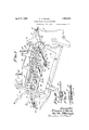
Fig. 1 is a perspective rear view of a shear lug machine having; the invention embodied therein;
Fig. 2 is a plan view of the same;
Fig. 3 is a fragmentary perspective front view of the shearing machine, on a reduced o scale;
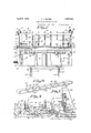
Fig. 4 is a fragmentary detail view principally in section taken on the line 4% of Fig. 1, with some parts shown in different positions by broken lines;
Fig. 5 is a fragmentary view principally in rear ekwation with some parts sectioned on the line 55 of Fig. 1;
Fig. 6 is a detail view partly in side elevation and partly in vertical section taken on the line 66 of Fig. 1, on an enlarged scale;
Fig. T a detail view principally in section taken on the line 7-7 of Fig. 6;
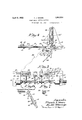
Fig. 8 is a detail View principally in section taken on the line 88 of Fig. 3, on an enlarged scale:
Fig. 9 a perspective view of the rear gauge removed from the machine;
Fig. 10 is a detail view with some parts sectioned on the line 1010 of Fig. 1, on an 4!) enlarged scale; and
Fig. 11 is a detail view with some parts sectioned on the line 11-11 of Fig. 1, on an enlarged scale.
For the purpose of illustrating the invention, as applied to a shearing machine, there is illustrated in the drawings such a machine and of the parts thereof, it is only necessary to note the frame end members 12, bed 13, lower shearing knife 14 and cooperating up per shearing knife 15 carried by a reciprowrung bar 16 mounted in vertical Ways on said end members. This upper knife bar 16 is rcci irocated by power actuated connections including a belt 17, which runs over a pulley 18 on a shaft 19 journaled in the end frame members 12. For the purpose of this case it is not thought necessary to show the operating connections from the shaft 19 to the knife bar 16. v i
A front gauge 20, mounted on a pair of brackets 21 on the front of the bed 13 is adjustably secured thereto by nut-equipped bolts 29., which extend through slotsin said gauge and are anchored in T-slots 23 in said brackets for adjustment toward or from the 55 knives 1 1 155.
A work hold-down 24 is adjustably mounted on the face ofthe knife bar 16 and has formed in its lower longitudinal edge portion a multiplicity of long notch-like openthrough which the cutting line for the seen. This type of hold-down the work at a plurality of longitudinally spaced points and between said points the work is loose. The hold down is yieldingly held pressed on the work by coiled springs 25, which permit the hold-down to come in contact with the work and thereafter remain stationary and hold the work while the upper knife 15 continues its downward movement for cooperation with the'lower knife 14 to produce a shearing action.
A pair of side gauges 18 are detachably secure to the bed 13, adjacent to each side frame member 12, and extend at right angles to the shearing edge of the lower knife 14. The parts thus far described are of standard and well-known construction. 90
Referring now in detail to the invention: As previously stated the knife bar 16 13 mounted in ways and which ways are in the form of long notches, in the rear vertical edge portions of the frame end portions 12, that are covered by castings detachably secured by bolts to said members. When the invention is applied to a shearin machine as an attachment, these castings will be removed and castings of the type shown substituted therefore and indicated by the numeral 26. Said castings 26.are provided, at thei lower end portions, withrearwardly projecting bosses 27. In actual embodiment of the invention in a shearing machine at the time of manufacture, the castings'26 will be a part of'the standard equipment.
A rear gauge 28 is mountedon-a pair of horizontal rearwardlv projecting guide .rods 29, the front ends of which are rigidlv se .eured in the bosses 27 which are on relatively fixed .partson the machine and are alw s stationary. This rear gauge 28 is in the form .of an'angle bar, thehorizontalflange of which extends rearward, and the vertical. flange of which-extendsdownwards, see Fig. 10. n .theendsof-thisrgauge 28 are hossed bearings 3O slidably mounted on theguide rods and support :said gauge for "horizontal adjust- ,ment toward and from .the knives .14 Attachedto the guide rods 29, rearwardly of .the.;gauge;28.-.is a pair of split clamp-acting .a-butments 31 for said gauge and are frictionally secured theretoby screws 32. h i- :crometer screws 33, mounted in the abutmentsi31, impinge. against the gauge 28 and :hold-thesame adj ustedin respect to the knives Dbviously, by-acljusting the abutments 31 on theguide'rods 29, .thegauge 28 may be set different distances rearward of .the knives 1,4.15 and by operating the micrometer .screwsi33, said gaugemavbe angnlarly ad- ,justedto setthe same parallel to said knives. Aftertheflgauge 28 has beenadjusted hv-th .micrometer screws 33, the same is rigidly se- .curedtotheguide rods 29 bythumbscrews 34, which have threaded engagement with the bearings and impinge against saidrods.
,A plur-ality of forwardly proiectin g fingers "35 'aremountediin bossed bearings 36 onthe underside of the gauge 28 for endwise adjustment-towarTd or'from the knives 1415 and "areheld where gpositioned'by set-screws 37.
' which have threaded engagement with the gauge 28 and impinge against said fingers. 'The'forward end portions of these guide fingers 35 are curved upwardly and forwardly to direct a piece of sheet metal thereunder as the;same3is':moved 'rearwardly for contact with the gauge :28 .andhold the on a support, as willpresently appear.
.A combined supporting and releasing device is provided'for holding a-sheet ofrmeta l X in the machine, positioned against the gauge 28 to be cut by the knives 1 l15 and thereafter release the same. This combined supporting and releasing device includes a plurality of rearwardly projecting horizontal arms 38, the front end portion of which are curved forwardly and downwardly and attached by adjustable locking joints 39 to the upper ends of forwardly and rearwardly inclined levers 40. These levers 40 are square in cross-section, mounted in correspondingly formed diametrically extended seats in arock shaft .41 forradial adjustment-and are held where adjusted by set-screws 42 having threaded engagement with said shaft and project into any one set of a plurality of longi- ;tu dinally spaced seats 43 in the levers 40. The joints 39 include half hubs, on the adjacent ends of the arms 38 and levers 40, the opposingfaces of which have serrated interlocking engagement, are pivotally connected and held interlocked by thumb-nut equipped bolts, see Fig. 7. Therock shaft 41 isjournaled in the bosses 27 belowtheguide rods 29.
In the adjustment of. the arms 38, as shown, their upper faces are i the plane of the bed 13, andtheir free rear end portions extend under the gauge. 28 and in notches 4 formed in the vetrical flange thereof. The rock shaft 41 is held againstzrotation, withtthe arms 38 in operative positions as shown in the drawings, by a hand-crank 45 secured to the left-hand on d of said rock shaft and having in its hand-piece a spring projected lock plunger 46, which extends into a seat in a lock plate .47 on-the adjacent'frame end member 12.
To release a piece of metal, cut from the sheet X by the-knives 1415, the hand-crank 545 is operated toreek-the shaft ll'into a position to swing the arms 38 downward, as shown by broken lines in Fig. 4, and permit said piece of metal to slide from the arms 38 under the-action of gravity.
By reference to Fig. l, it will be noted that the rock shaft l-l isrearwardly spaced from .the machine to leave gap thcrebetween for the escape of short pieces of metal cut by the knives 1415. A deflecting plate 48, attached tothe rear end of the machine, is provided for directing these short pieces-of metal from the machine asthey are precipitated from the bed'i13.
For holding the sheet X- on the arms 38 at the forward end portions thereof and for causing the same to move with said arms, when released, there is provided a pair ofupright fingers49 havinglaterally bent upper end'portions that project toward each other overthe sheet X, see Fig. 5. For narrow sheets only one of the fingers as will be used. These fingers 49, at their lower ends, are attached to the outer ends'of levers 50, 'which are similar to the levers 40, by joints 'Slwhich are similar to the joints 39. Said arms 38 are mounted in diametrically extendedseats ll cured by screws to the underside of said hold down, see Fig. 4, and thereby close the long notches therein.
The operation of the above described n1achine may be briefly described as follows: the sheet X is first placed on the bed 13 with one of its longitudinal edges against one of the side gauges 13 to square the same with knives 14-15, and the upper knife 15 operated to trim the inner end portion of said sheet, as shown, at the left by dotted lines in Fig. 2. The sheet is then moved rearwardly between the knives 14-45, onto the arms 38, under the fingers 49 and and into engage ment with the gauge 28, which is set the proper distance from the knives 14-15 for the length of the piece of metal to be cut from the sheet. The fingers 49 and 35 hold the sheet flat on the arms 38 and take the warp or twist out of the same so that said sheet is flat the full distance between the knives and gauge. By thus holding the sheets flat be tween the knives and gauge, successive pieces, as they are cut from the sheet, are accurately measured and all of the same size. During the rearward movement of the sheet, the upwardly curved ends of the finger 35 direct said sheet thereunder and onto the imdcrlying arms 38 for engagement with the gauge The fingers 49, in addition to holding the sheet flat on the arms 38 at the front end thereof cause the piece cut from the sheet to move with the arm 38 as they are moved into inoperative positions to release said piece.
The tendency of the piece cut from the sheet is to cling to the gauge 28 and not follow the arms 38 as they are moved into inoperative position and thereby interfere with its dis charge from the combined supporting and re leasing device but the fingers 49 draw said 1 the waste therefrom. For this class of work,
the front and rear gauges must be set the same distance from the cutting line, on which the knives 14-45 operate.
The vertical adjustment of the fingers 49 t is such that a sheet will freely pass thereunder when being fed to the gauge 28. To vary the vertical adjustment of the fingers 49, for sheets of different thicknesses and when several sheets are supported, the one upon the other to be simultaneously cut, the rock shaft 41 is turned about its longitudinal axis to raise or lower the levers 50 at the joints 51 and said joints adjusted to position the fingers 49 in upright positions.
To adjust the rock shaft 41, on its longitudinal axis, the set-screw, which secures the hand crank 45 to the rock shaft 41, is loosened and said shaft adjusted in respect to the hand crank 45 which is held by the lock 46-47, and thereafter said set-screw is again tightened to secure the hand crank 45 to the rock shaft 41. This adjustment of the rock shaft 41 throws the arms 38 out of adjustment and to re-adjust the same, the joints 39 are loosened to permit said arms to be set in horizontal positions and the levers are radially adjusted in the rock shaft 41 to position. the upper faces of the arms 38 in the plane of the bed 13. After the arms 38 are properly adjusted, the joints 39 are again locked, and the shafts 40 secured by the setscrews 42 to the rock shaft 41.
In case it is desirable to support a short piece to be cut from a sheet or in other words a piece that is too short to be supported 011 the arms 38, said arms are removed from the levers 40 and short arms 54 substituted therefor, as indicated by broken lines in Fig. 4. These short arms 54 project forward from the levers 40 with their free ends terminating close to the knife 14 and when operated to release a piece of work thereon, are moved by said levers into upwardly inclined positions.
What I claim is:
1. In a machine of the class described, the combination with a main frame and cutting mechanism, of a guide on the main frame and held stationary thereby in respect to the cutting mechanism, a rear gauge mounted on the guide, a work supporting and releasing device between the cutting mechanism and gauge and operable to discharge a piece of work between said device and gauge, and means for operating said device to discharge a piece of work therefrom.
2. In a machine of the class described, the combination with a main frame and cutting mechanism, of a guide on the main frame and held stationary thereby in respect to the cutting mechanism, a rear gauge mounted on the guide, a work support between the cutting mechanism and gauge, a plurality of forwardly projecting guide members on the gauge overlying the support for directing a piece of work to the gauge and holding the same on the support, and means for causing'a piece of work on said device to move therewith phen operated to discharge said piece thererom.
3. .In a machine of the class described, the .combination with-a main frame and cutting mechanism, of aguide on the main frame and held stationarythereby in respect to the cutiting mechanism, a rear gauge mounted on the uide, a 'worksupport between the cutting :mechanism and gauge, and a plurality of guide members on the gauge for directing a piece of work to the gauge and holding the same on the support, a retaining member mounted'on said device to overlie a piece of work thereon and cause said piece to move with "the device when operated to discharge the piece of worktherefrom.
4;. .In a machine of theclass described, the combination with a main frame and cutting n1ecl1a nism, of a guide on the main frame and held stationarythereby in respect to the cutting mechanism, a rear gauge mounted on the guide, a work support between the cutting mechanism and gauge, and a plurality of guide members on the gauge for directing a piece of work to the gauge and holding the .same on the support, a retaining member 'mounted onsaid device to overliea piece of work thereon and cause said piece to move with the device when operated to discharge lthe'piece of work therefrom, said retaining .memberbeing adjustable to vary the distance between said member and device.
"5. In a machine of the class described, the combination with a main frame and cutting mech'anism, ofa'guide on the main frame and .held'stationarytherebyin respect to the cut :ting mechanism, a rear gauge mounted on the'guidaa combined work supporting and :releasing device comprising a rock shaft rea"- ward of the cutting mechanism, operatin means for the rock shaft normally holding th same in a predetermined position, and rearwar'dly projecting arms on the rock shaft f r supporting a piece of work between the cut-- ting mechanism and gauge, said rock shaft being operable to move the arms into a position to discharge'thepiece of work therefrom 6. In a machine of the class described, the combination with a-main frame and cutting mechanism, of a guide on the main frame and heldv stationary thereby in respect to the cut ting mechanism. a rear gauge mounted on the guide, a combined work supporting and releasing device comprising a rock shaft res."- ward 'of the cutting mechanism. open-ting means'for the rock shaft normally holding the same'in a predetermined position. and rearwardly projecting arms on the rock shaftfor supporting a piece of work between the cutting mechanism and gauge, said rock sh ft being operable to move the arms int-o a position to discharge the piece of work there- 'from, saidarms being mounted on the rock 'shaftr for=vertical adjustment.
7. In a machine ofthe class described, he combination witha mainframe and cutting mechanism, of a guide on the main frame and of work therefrom, and guide members on the gauge for directing apiece of workthereto and holding the same on the arms.
8. In a machine of the class described,'the combination with a main frameandcutting mechanism, of a guide on the mainframe and held stationary'thereby in respectto the cutting mechanism, a rear gauge mounted on the guide, a combined worksupporting and releasing device comprising a rock shaft, operating means for the rock shaft normally holding the same in a predetermined position, arms on the rockshaft for supporting apiece of work between the cutting mechanism and gauge, said rock shaft being operable to move the arms into a position to discharge the piece of work therefrom, and a retaining member on the rock shaft forcausing a piece of work on the arms to move therewith when operated torelease-said piece therefrom.
9. In a machine of the'class described,tthe combination with a mainframe-and cutting mechanism, of a guide on the main frame and held stationary'thereby in respect to'the'cutting mechanism, a rear gauge mounted on'the guide, a combined work supporting and:releasing device comprising a rock shaft, operating means for the rock shafttnormally holding the same in a predetermined position, arms on the rock shaft for supporting a piece of work between the cuttingmechanism and gauge, said rock shaft being operable to move the arms into a position to discharge'the piece of work therefrom, and a retaining member on the rock shaft for causing a piece of work on the armsto move therewithwhen operated to release said piece therefrom, said retaining member being vertically adjustable in respect to thearms.
10. In a machine of the class described,-tl1e combination with a main frame and cutting mechanism, of a guide on the main frame and held stationarythereby inrespect to the-cutting mechanism, a rear gauge mounted on the guide, a combined work supporting and releasing device comprising a rock shaft, operating means for the rock shaft normally holding the same in a predetermined position, levers mounted on the rock shaft for radial adjustment, arms for supporting a piece of work between the cutting mechanism and gauge, and adjustable oints securing'the arms to the levers for angular movement in respect thereto. I
11. In a machine of the class described,
the combination with a main frame and cutting mechanism, of a guide on the main frame and held stationary thereby in respect to the cutting mechanism, a rear gauge mounted on the guide, a combined work supporting and releasing device comprising a rock shaft, operating means for the rock shaft normally holding the same in a predetermined position, levers mounted on the rock shaft for radial adjustment, arms for supporting a piece of work between the cutting mechanism and gauge, and adj ustable joints securing the arms to the levers for angular movement in respect thereto, said joints being operable to hold the arms in either a forwardly or rear wardly projecting position.
12. In a machine of the class described, the combination with a main frame and cutting mechanism, of a guide on the main frame and held stationary thereby in respect to the cutting mechanism, a rear gauge mounted on the guide, a combined supporting and releasing device comprising a rock shaft, operating means for the rock shaft normally holding the same in a predetermined position, arms on the rock shaft for supporting a piece of work between the cutting mechanism and gauge, said rock shaft being operable to move the arms into a position to discharge a piece of work therefrom, and a retaining member on the rock shaft for causing the piece of work on the arms to move therewith when operated to release said piece therefrom.
13. In a machine of the class described, the combination with a main frame and cutting mechanism, of a guide on the main frame and held stationary thereby in respect to the cut ting mechanism, a rear gauge mounted on the guide, a combined supporting and releasing device comprising a rock shaft, operating means for the rock shaft normally holding the same in a predetermined position, arms on the rock shaft for supporting a piece of work between the cutting mechanism and gauge, said rock shaft being operable to move the arms into a position to discharge a piece of Work therefrom, a lever mounted on the rock shaft for radial adjustment, a retaining memher for causing a piece of Work on the arms to move therewith when operated to release said piece therefrom, and an adjustable joint rigidly connecting the retaining member to the lever for angular adjustment in respect thereto.
14:. In a machine of the class described, the combination with a main frame and cutting mechanism, of a guide on the main frame and held stationary thereby in respect to the cutting mechanism, a rear gauge mounted on the guide, and a work support between the cutting mechanism and gauge and pivoted at one end for dumping the work after the severing operation by the cutting mechanism.
15. The structure defined in claim 14 in further combination with a forwardly pro- FRANCIS J. MOORE.
Priority Applications (1)
| Application Number | Priority Date | Filing Date | Title |
|---|---|---|---|
| US395292A US1852534A (en) | 1929-09-26 | 1929-09-26 | Sheet metal cutting machine |
Applications Claiming Priority (1)
| Application Number | Priority Date | Filing Date | Title |
|---|---|---|---|
| US395292A US1852534A (en) | 1929-09-26 | 1929-09-26 | Sheet metal cutting machine |
Publications (1)
| Publication Number | Publication Date |
|---|---|
| US1852534A true US1852534A (en) | 1932-04-05 |
Family
ID=23562442
Family Applications (1)
| Application Number | Title | Priority Date | Filing Date |
|---|---|---|---|
| US395292A Expired - Lifetime US1852534A (en) | 1929-09-26 | 1929-09-26 | Sheet metal cutting machine |
Country Status (1)
| Country | Link |
|---|---|
| US (1) | US1852534A (en) |
Cited By (8)
| Publication number | Priority date | Publication date | Assignee | Title |
|---|---|---|---|---|
| US2603338A (en) * | 1952-07-15 | Sheet metal transfer device | ||
| US2719443A (en) * | 1953-03-16 | 1955-10-04 | Rohr Aircraft Corp | Drop hammer |
| US2836242A (en) * | 1955-10-07 | 1958-05-27 | Olin Mathieson | Locator |
| US2964982A (en) * | 1954-02-08 | 1960-12-20 | New Britain Machine Co | Stock stop |
| US3176559A (en) * | 1962-08-30 | 1965-04-06 | Athos Steel And Aluminum Inc | Indexing device for squaring shear |
| US3861258A (en) * | 1972-08-10 | 1975-01-21 | William Taylor Irvine | Receiving table for a guillotine |
| US4301700A (en) * | 1980-03-10 | 1981-11-24 | Unicel Corporation | Cutting apparatus |
| US4422815A (en) * | 1982-01-04 | 1983-12-27 | Western Automation Corporation | Machine tool support and discharge apparatus |
-
1929
- 1929-09-26 US US395292A patent/US1852534A/en not_active Expired - Lifetime
Cited By (8)
| Publication number | Priority date | Publication date | Assignee | Title |
|---|---|---|---|---|
| US2603338A (en) * | 1952-07-15 | Sheet metal transfer device | ||
| US2719443A (en) * | 1953-03-16 | 1955-10-04 | Rohr Aircraft Corp | Drop hammer |
| US2964982A (en) * | 1954-02-08 | 1960-12-20 | New Britain Machine Co | Stock stop |
| US2836242A (en) * | 1955-10-07 | 1958-05-27 | Olin Mathieson | Locator |
| US3176559A (en) * | 1962-08-30 | 1965-04-06 | Athos Steel And Aluminum Inc | Indexing device for squaring shear |
| US3861258A (en) * | 1972-08-10 | 1975-01-21 | William Taylor Irvine | Receiving table for a guillotine |
| US4301700A (en) * | 1980-03-10 | 1981-11-24 | Unicel Corporation | Cutting apparatus |
| US4422815A (en) * | 1982-01-04 | 1983-12-27 | Western Automation Corporation | Machine tool support and discharge apparatus |
Similar Documents
| Publication | Publication Date | Title |
|---|---|---|
| US1852534A (en) | Sheet metal cutting machine | |
| US2742935A (en) | Kick-off mechanism for sawing machine | |
| US1796697A (en) | Woodworking machine | |
| US3176559A (en) | Indexing device for squaring shear | |
| US944019A (en) | Stripper or cutter for embroidery, tucking, and similar material. | |
| US2365605A (en) | Machine for cutting sheet material | |
| US1746930A (en) | Attachment for cloth-cutting machines | |
| US1714382A (en) | Cloth cutter | |
| US1675563A (en) | Mitering and cutting machine | |
| US1038215A (en) | Rip-saw machine. | |
| US2240983A (en) | Safety saw guard | |
| US930744A (en) | Paper-trimming machine. | |
| US2090649A (en) | Indexing attachment for slotting machines | |
| US1142974A (en) | Shearing-machine. | |
| US2015250A (en) | Cutting machine | |
| US324842A (en) | Scroll-sawing machine | |
| US1573705A (en) | Edging gauge | |
| US274273A (en) | Paper-cutting machine | |
| US1500122A (en) | Grinding machine | |
| GB516778A (en) | Improvements relating to slicing machines | |
| US1544290A (en) | Saw table | |
| US2165953A (en) | Cutting machine | |
| US1210476A (en) | Meat-slicing machine. | |
| US1285801A (en) | Band sawing-machine. | |
| US1537285A (en) | Side-gauge-locking device for slitters |