US185252A - Improvement - Google Patents
Improvement Download PDFInfo
- Publication number
- US185252A US185252A US185252DA US185252A US 185252 A US185252 A US 185252A US 185252D A US185252D A US 185252DA US 185252 A US185252 A US 185252A
- Authority
- US
- United States
- Prior art keywords
- attached
- pulley
- grain
- belt
- cylinder
- Prior art date
- Legal status (The legal status is an assumption and is not a legal conclusion. Google has not performed a legal analysis and makes no representation as to the accuracy of the status listed.)
- Expired - Lifetime
Links
Images
Classifications
-
- A—HUMAN NECESSITIES
- A01—AGRICULTURE; FORESTRY; ANIMAL HUSBANDRY; HUNTING; TRAPPING; FISHING
- A01F—PROCESSING OF HARVESTED PRODUCE; HAY OR STRAW PRESSES; DEVICES FOR STORING AGRICULTURAL OR HORTICULTURAL PRODUCE
- A01F12/00—Parts or details of threshing apparatus
- A01F12/10—Feeders
- A01F12/12—Feeders without band-cutters
Definitions
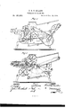
- Figure l is a side view of my improved machine.
- Fig. 2 is a vertical longitudinal section of the same.
- Fig. 3 is a detail view of the device for operating the shaker.
- the object of this invention is to furnish an improved machine for thrashing and cleaning grain, which shall be so constructed that it may be run by hand or other power, and which, at the same time, shall be simple in construction and efi'eetive in operation.
- - A is the frame of the machine, to the middle parts of the side bars of which are attached brackets B, in bearings in which revolve the journals of the thrashing-cylinder.
- the thrashing-cylinder is formed by attaching the ends of bars 0 to two disks, D, which disks are attached at their centers to the shaft E that carries the cylinder.
- the teeth F may be attached to the bars 0 by screwing them into screw-holes formed in said bars, or by inserting them in plain holes in the bars, and securing them by nuts screwed upon their inner ends.
- the concave G may be made with or without teeth, and when without teeth it may be corrugated or made smooth, as may be desired.
- the concave G may be secured to the-frame A adjustably by bolts, so that it may be adjusted closer to or farther from the cylinder, as may be desired.
- I is the feed-table, which is placed upon the forward end of the frame A, and is secured in place adjustably by bolts, so that it may be moved forward or back, according as the stalks of the grain may be longer or shorter.
- To theinner end of the feed-table I are pivoted two feed-rollers, J, the lower one of which is ribbed or corrugated.
- the journals of the upper feed-roller J revolve in slots, so that it may rise to adjust itself to the thickness of the grain, and is held down to its work by spiral springs K, the upper ends of which are attached to the journals of the said roller, and their lower ends are attached to the table I.
- the feed-table I may be provided with an endless-belt carrier, L, that passes around the lower roller J and around a roller, M, pivoted to the outer end of the table I.
- an endless-belt carrier, L that passes around the lower roller J and around a roller, M, pivoted to the outer end of the table I.
- hinged wings N To the sides of the feed-table I are hinged wings N, which are supported, when turned outinto a position for use, by restingupon the ends of a cross-bar, 0, attached to the said table I.
- the straw and grain pass from the thrashing-cylinder to the carrier P, which is secured detachably and adjustably to the frame A, so that it may be detached when not required for use, and may be adjusted at any desired inclination.
- the straw is carried up by the carrier, and is discharged at the rear end of the machine. a
- the grain falls upon the close bottom of said carrier, slides down it, and falls upon the chaff-carrier Q, through which it passes to the screens.
- the rollers of the chaff-carrier Q are pivoted to the shaker R.
- the grain passes down the lower screen into the spout S, through which it passes out of the machine. uThe small seeds pass through the lower screen, slide down the close bottom of the shaker R, and pass out beneath the spout S.
- the grain, while passing from the straw-carrier P to the spout S, is exposed to a current of air from the fan-blower T, placed in the lower forward part of the frame A.
- crank-pulleys U V To the journals of the lower feed-roller J are attached crank-pulleys U V, to the cranks of which the power is applied when the machine is to be run by hand.
- a belt, W Around the pulley U, which is made of the same size as the pulley V, passes a belt, W, which is crossed and passed around a pulley, X, attached to the end of the counter-shaft Y.
- the tension of the belt W is regulated by the pulley w, which rests upon it, and which is pivoted to the lower part of the bar 20
- the bar 20 is pivoted at its upper end to the frame A, so that it may be adjusted to regulate the tension of the belt W, as required.
- the countershaft Y revolves in bearings attached to the rear end of the frame A, and to its other end is attached a large pulley, Z, around which passes a belt, A.
- the belt A also passes around a pulley, B, attached to the journalv of the thrashing-cylinder.
- To the end of the counter-shaft Y is also attached a small pulley, 0, around which passes a belt, D.
- the belt D is crossed and passes around a pulley, E, attached to the journal of the upper roller of the straw carrier 1?.
- Around the crank-pulley V passes a belt, F, which is crossed and is passed around a pulley, G, attached to the shaft of the fan-blower T.
- a crank-pin to which is pivoted the end of a connecting-rod, H.
- the other end of the connecting-rod H is pivoted to the outer arm of the crank-lever I, which is pivoted at its angle to a rod, J, attached to the frame A.
- the other arm of the lever I is pivoted to the side of the shaker B, so that the said shaker may be driven from the fanshaft.
- the forward part of the shaker R is supported by spring-bars K, the lower ends of which are attached to its sides, and their upper ends are attached to the top bars of the frame A.
- the rear end of the shaker R is loosely hung upon the rod L, attached to the vframe VA.
- the thrashing cylinder, and the straw-carrier are covered with a casing, M, to prevent the grain and straw from being scattered about by the action of the thrasher.
- the lower part of the machine should also be incased, to confine the blast and direct it against the grain to properly clean it.
- the sliding feed-table I of a thrasher made adjustable to and from the cylinder, and provided with feeding belt L, and having roller J substantially as and for the purpose specified.
Landscapes
- Life Sciences & Earth Sciences (AREA)
- Environmental Sciences (AREA)
- Apparatuses For Bulk Treatment Of Fruits And Vegetables And Apparatuses For Preparing Feeds (AREA)
Description
G. R. H. MILLER.
I THRASHING-MACHINE. No.185,Z5Z. Patented Dec. 12, 1876.
mum in on:
BY ATTURNEYS.
THE GRAPHIC CD. N3.
GEORGE R. H. MILLER, OF OREGON CITY, OREGON.
IMPROVEMENT IN THRASHING-MAOHlNES.
Specification forming part of Letters Patent No. 155,252, dated December 12, 1876; application filed July 31, 1876.
To all whom it may concern:
Be it known that I, GEORGE R. H. MILLER, of Oregon City, in the county of Olackamas and State of Oregon, have invented a new and Improved Combined Grain Thrasher and Gleaner, of which the following is a specification:
Figure l is a side view of my improved machine. Fig. 2 is a vertical longitudinal section of the same. Fig. 3 is a detail view of the device for operating the shaker.
The object of this invention is to furnish an improved machine for thrashing and cleaning grain, which shall be so constructed that it may be run by hand or other power, and which, at the same time, shall be simple in construction and efi'eetive in operation.
The invention will first be described in connection with the drawing, and then pointed out in the claim.
- A is the frame of the machine, to the middle parts of the side bars of which are attached brackets B, in bearings in which revolve the journals of the thrashing-cylinder. The thrashing-cylinder is formed by attaching the ends of bars 0 to two disks, D, which disks are attached at their centers to the shaft E that carries the cylinder. The teeth F may be attached to the bars 0 by screwing them into screw-holes formed in said bars, or by inserting them in plain holes in the bars, and securing them by nuts screwed upon their inner ends. To the frame A, directly beneath the thrashing-cylinder, is secured the concave G,'
the teeth E of which may be so arranged that they may mesh into the teeth F of the cylinder or not, as may be desired. The concave G may be made with or without teeth, and when without teeth it may be corrugated or made smooth, as may be desired.
The concave G may be secured to the-frame A adjustably by bolts, so that it may be adjusted closer to or farther from the cylinder, as may be desired.
I is the feed-table, which is placed upon the forward end of the frame A, and is secured in place adjustably by bolts, so that it may be moved forward or back, according as the stalks of the grain may be longer or shorter. To theinner end of the feed-table I are pivoted two feed-rollers, J, the lower one of which is ribbed or corrugated. The journals of the upper feed-roller J revolve in slots, so that it may rise to adjust itself to the thickness of the grain, and is held down to its work by spiral springs K, the upper ends of which are attached to the journals of the said roller, and their lower ends are attached to the table I. The feed-table I may be provided with an endless-belt carrier, L, that passes around the lower roller J and around a roller, M, pivoted to the outer end of the table I. To the sides of the feed-table I are hinged wings N, which are supported, when turned outinto a position for use, by restingupon the ends of a cross-bar, 0, attached to the said table I.
The straw and grain pass from the thrashing-cylinder to the carrier P, which is secured detachably and adjustably to the frame A, so that it may be detached when not required for use, and may be adjusted at any desired inclination. The straw is carried up by the carrier, and is discharged at the rear end of the machine. a The grain falls upon the close bottom of said carrier, slides down it, and falls upon the chaff-carrier Q, through which it passes to the screens. The rollers of the chaff-carrier Q are pivoted to the shaker R. The grain passes down the lower screen into the spout S, through which it passes out of the machine. uThe small seeds pass through the lower screen, slide down the close bottom of the shaker R, and pass out beneath the spout S. The grain, while passing from the straw-carrier P to the spout S, is exposed to a current of air from the fan-blower T, placed in the lower forward part of the frame A.
To the journals of the lower feed-roller J are attached crank-pulleys U V, to the cranks of which the power is applied when the machine is to be run by hand. Around the pulley U, which is made of the same size as the pulley V, passes a belt, W, which is crossed and passed around a pulley, X, attached to the end of the counter-shaft Y. The tension of the belt W is regulated by the pulley w, which rests upon it, and which is pivoted to the lower part of the bar 20 The bar 20 is pivoted at its upper end to the frame A, so that it may be adjusted to regulate the tension of the belt W, as required. The countershaft Y revolves in bearings attached to the rear end of the frame A, and to its other end is attached a large pulley, Z, around which passes a belt, A. The belt A also passes around a pulley, B, attached to the journalv of the thrashing-cylinder. To the end of the counter-shaft Y is also attached a small pulley, 0, around which passes a belt, D. The belt D is crossed and passes around a pulley, E, attached to the journal of the upper roller of the straw carrier 1?. Around the crank-pulley V passes a belt, F, which is crossed and is passed around a pulley, G, attached to the shaft of the fan-blower T. To the pulley G is attached a crank-pin, to which is pivoted the end of a connecting-rod, H. The other end of the connecting-rod H is pivoted to the outer arm of the crank-lever I, which is pivoted at its angle to a rod, J, attached to the frame A. The other arm of the lever I is pivoted to the side of the shaker B, so that the said shaker may be driven from the fanshaft. The forward part of the shaker R is supported by spring-bars K, the lower ends of which are attached to its sides, and their upper ends are attached to the top bars of the frame A. The rear end of the shaker R is loosely hung upon the rod L, attached to the vframe VA. The thrashing cylinder, and the straw-carrier are covered with a casing, M, to prevent the grain and straw from being scattered about by the action of the thrasher. The lower part of the machine should also be incased, to confine the blast and direct it against the grain to properly clean it.
Having thus described my invention, what claim as new, and desire to secure by Letters Patent, is
The sliding feed-table I of a thrasher, made adjustable to and from the cylinder, and provided with feeding belt L, and having roller J substantially as and for the purpose specified.
GEORGE E. 'H. MILLER.
Witnesses:
JOHN G. PILSBURY, JOHN L. BARLOW, W. O. JOHNSON.
Publications (1)
| Publication Number | Publication Date |
|---|---|
| US185252A true US185252A (en) | 1876-12-12 |
Family
ID=2254657
Family Applications (1)
| Application Number | Title | Priority Date | Filing Date |
|---|---|---|---|
| US185252D Expired - Lifetime US185252A (en) | Improvement |
Country Status (1)
| Country | Link |
|---|---|
| US (1) | US185252A (en) |
-
0
- US US185252D patent/US185252A/en not_active Expired - Lifetime
Similar Documents
| Publication | Publication Date | Title |
|---|---|---|
| US185252A (en) | Improvement | |
| US131192A (en) | Improvement in grain thrashers and cleaners | |
| US310679A (en) | Half to irenaeus conder | |
| US141526A (en) | Improvement in thrashing-machines | |
| US694540A (en) | Grain-cleaner. | |
| US488730A (en) | Thrashing-machine | |
| US339815A (en) | Band-cutter and feeder | |
| US359044A (en) | weleee | |
| US358834A (en) | Thrashing-machine | |
| US640939A (en) | Beating mechanism for threshing-machines. | |
| US336366A (en) | Horace a | |
| US322886A (en) | aitken | |
| US153703A (en) | Improvement in combined harvesters and thrashers | |
| US720637A (en) | Band-cutter and feeder for threshing-machines. | |
| US353885A (en) | Corn-sheller | |
| US261867A (en) | Thrashing and separating machine | |
| US230622A (en) | Thrashing-machine | |
| US72940A (en) | Improvement in field threshing-machine | |
| US113345A (en) | Improvement in field thrashing-machines | |
| US727300A (en) | Corn husker and shredder. | |
| US132822A (en) | Improvement in thrashing-machines | |
| US303072A (en) | Band cutter and feeder | |
| US182318A (en) | Improvement in combined clover-hulling and thrashing machine | |
| US446644A (en) | Thrashing-machine | |
| US266394A (en) | Band cutter and feeder |