US1852525A - Condenser seal - Google Patents
Condenser seal Download PDFInfo
- Publication number
- US1852525A US1852525A US426238A US42623830A US1852525A US 1852525 A US1852525 A US 1852525A US 426238 A US426238 A US 426238A US 42623830 A US42623830 A US 42623830A US 1852525 A US1852525 A US 1852525A
- Authority
- US
- United States
- Prior art keywords
- housing
- condenser
- discharge
- discharge port
- conveyer
- Prior art date
- Legal status (The legal status is an assumption and is not a legal conclusion. Google has not performed a legal analysis and makes no representation as to the accuracy of the status listed.)
- Expired - Lifetime
Links
- HCHKCACWOHOZIP-UHFFFAOYSA-N Zinc Chemical compound [Zn] HCHKCACWOHOZIP-UHFFFAOYSA-N 0.000 description 13
- 239000000463 material Substances 0.000 description 9
- 239000008187 granular material Substances 0.000 description 8
- 239000011701 zinc Substances 0.000 description 5
- 229910052725 zinc Inorganic materials 0.000 description 5
- 238000003723 Smelting Methods 0.000 description 3
- 230000005494 condensation Effects 0.000 description 2
- 238000009833 condensation Methods 0.000 description 2
- 238000010276 construction Methods 0.000 description 2
- 239000002826 coolant Substances 0.000 description 2
- 238000000034 method Methods 0.000 description 2
- UGFAIRIUMAVXCW-UHFFFAOYSA-N Carbon monoxide Chemical compound [O+]#[C-] UGFAIRIUMAVXCW-UHFFFAOYSA-N 0.000 description 1
- 241000290143 Pyrus x bretschneideri Species 0.000 description 1
- 229910002091 carbon monoxide Inorganic materials 0.000 description 1
- 238000007599 discharging Methods 0.000 description 1
- 239000002360 explosive Substances 0.000 description 1
- 239000007789 gas Substances 0.000 description 1
- 238000004519 manufacturing process Methods 0.000 description 1
- 239000000203 mixture Substances 0.000 description 1
- 239000012254 powdered material Substances 0.000 description 1
- 239000013589 supplement Substances 0.000 description 1
Images
Classifications
-
- C—CHEMISTRY; METALLURGY
- C22—METALLURGY; FERROUS OR NON-FERROUS ALLOYS; TREATMENT OF ALLOYS OR NON-FERROUS METALS
- C22B—PRODUCTION AND REFINING OF METALS; PRETREATMENT OF RAW MATERIALS
- C22B19/00—Obtaining zinc or zinc oxide
- C22B19/04—Obtaining zinc by distilling
- C22B19/16—Distilling vessels
- C22B19/18—Condensers, Receiving vessels
-
- Y—GENERAL TAGGING OF NEW TECHNOLOGICAL DEVELOPMENTS; GENERAL TAGGING OF CROSS-SECTIONAL TECHNOLOGIES SPANNING OVER SEVERAL SECTIONS OF THE IPC; TECHNICAL SUBJECTS COVERED BY FORMER USPC CROSS-REFERENCE ART COLLECTIONS [XRACs] AND DIGESTS
- Y10—TECHNICAL SUBJECTS COVERED BY FORMER USPC
- Y10S—TECHNICAL SUBJECTS COVERED BY FORMER USPC CROSS-REFERENCE ART COLLECTIONS [XRACs] AND DIGESTS
- Y10S198/00—Conveyors: power-driven
- Y10S198/954—Overflow
Definitions
- My present invention relates to a seal adapted for condensers and to a method of ob taining the same.
- the invention is specifically concerned with the operationbf an apparatile for discharging zinc dust or blue powder from a condenser within which the same is all) produced.
- the invention contemplates in connection with a condenser, a discharge means at the bottom thereof for moving the condensed zinc towards a discharge port.
- the housing is provided surrounding the discharge means and a baffle or bafiles are provided depending from the top of the housing and straddling the feeding means at a point between the end of said means and the discharge port.
- the invention further consists in the novel arrangement, combination and construction of "parts and in the method of operating the same, more fully shown in the accompanying drawings and in the specification.
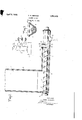
- Fig. 1 is a diagrammatic plan view of a smelter-condenser-discharge. combination
- FIG. 2' is a fragmentary sectional view through one of the condensers showing the iii-- ventlon, and
- Fig. 3 is a sectional-view along the line 3-3 of Fig. 2.
- a smelting unit diagrammatically indicated I at 1 which may be of ordinary type, deliver denser units 2.
- the condenser may be n single'units or a plurality thereof as desired.
- the walls 3 of the condensers are hollow for the circulating of a cooling medium to increase the condensation efliciency thereof.
- longitudinally extending housings 4 are provided, likewise with hollow walls for a cooling medium found necessary or desirable.
- the bottom of the housin 4 conforms as at 8 substantially to the configuration of the feedin means although a space exists between the ttom of the screw and the bottom of the housing 8.
- the spiral screw 7 terminates within the housing 4, andbetween the end of the screw and the discharge port 9 there is located one baflle or a pair of baflles l0 and 11 depending from. the op of the housing 4 and straddling the feeding means 5, although terminating short of the bottom of the housing.
- a condenser means to discharge granular material condensed therein toward a discharge port said discharge means comprising a shaft carrying a spiral conveyer vane.
- a housing for the discharge means, a fixed baflie dependin from the top thereof and straddling said s aft said vane terminating short of said baflle and a discharge port beyond the baflle.
- a condenser means to dischage granular material condensed therein toward a discharge portsaid discharge means comprising a shaft carrying a spiral conveyer vane, a housing for the discharge means, a plurality of spaced apart baflles depending from thetop of the housing and straddling said shaft said vane terminating short of said bafile, and a discharge port beyond the bailies.
- a condenser means to granular material condensed therein toward a discharge port
- said discharge means comprising a shaft carrying a spiral conveyer vane, a housing for the discharge means, a fixed baflle depending from the top thereof and straddling said shaft said vane terminating short of said baflle, the bafile terminating short of the bottom of the means comprising a shaft carrying a spiral conveyer vane, a housing for the discharge means, a plurality of spaced apart baflles depending from the top of the housing and straddling said shaft said vane terminating short of said bafile, the baifles terminating short of the bottom of the housing, and a discharge port beyond the baflles.
- a condenser means to discharge granular material condensed there- 1n toward a dlscharge port, and including a screw conveyer, a housing therefor having a curved bottom substantially conforming to the configuration of the conveyer, the screw portion of the conveyer terminating short of a dlscharge port, and a bafile depending from the top of the housing and straddling the conveyer. beyond the screw portion, the top of the housing beyond the bafile being open.
- a condenser means to discharge granular material condensed therein toward a discharge port and including a screw conveyer, a houslng therefor having a curved bottom substantially conforming to the configuration of thebottom of the con-' veyer, thescrew portion of the conveyer terminating short of a'discharge port and a plurality, of spaced apart baflles depending from the top of the housing and straddling the conveyer beyond the screw portion,
- a zinc dust condenser an elongated housing at the bottom thereof adapted to receive the condensed material, a conveyer for carrying the zinc dust from the bottom of the condenser into the housing,'a discharge port in the housing, a plurality of baflles between the condenser and the discharge port, depending from the top of the housing, the conveyer terminating short of the bafiles whereby the material discharged from the condenser will be banked up in a pile against the baflles and thus seal the housing against in-coming air the top of the housing between the bafiles being open.
- a condenser means-to discharge granular material condensed therein toward a discharge port said di harge
Landscapes
- Engineering & Computer Science (AREA)
- Chemical & Material Sciences (AREA)
- Manufacturing & Machinery (AREA)
- Materials Engineering (AREA)
- Mechanical Engineering (AREA)
- Metallurgy (AREA)
- Organic Chemistry (AREA)
- Manufacture And Refinement Of Metals (AREA)
Description
F. R. KEMMER April 5, 1932 CONDENSER SEAL Filec Feb 6, 1930 INYENTOR FRANK R. KENIMER ATTORNEY Patented Apr. 51, 1932 UNITED STATES PATENT OFFICE.
run: :a. xmmnn, or uacmconr, mtw Your, ABSIGNOR T summon: crummy COMPANY, or Nnw'Yonx, N. 1.,
a oonrom'rron or MAINE connmsnn SEAL Application filed. February a, 1800. Serial 10. 428,288.
My present invention relates to a seal adapted for condensers and to a method of ob taining the same. The invention is specifically concerned with the operationbf an apparatile for discharging zinc dust or blue powder from a condenser within which the same is all) produced.
in the production of zinc dust it is common practice to connect a condenser or a series of condensers, with a smelting furnace for the condensation of the zinc to the powdered form. In the operation of such an apparatus the smelting furnace and condensers are filled "with carbon monoxide and it is of extreme importance that air not be permitted access to the interior of the condensers or the smelter as explosive mixtures would thus be formed.
it is, therefore, among the primary objects of the invention to provide for the discharge of the condensed zinc in a manner which will preclude the leaking and back-passage of air through the discharge apparatus into the condenser. i
To this end the invention contemplates in connection with a condenser, a discharge means at the bottom thereof for moving the condensed zinc towards a discharge port. A
housing is provided surrounding the discharge means and a baffle or bafiles are provided depending from the top of the housing and straddling the feeding means at a point between the end of said means and the discharge port. As a result of the operation of such a mechanism, the condensedpowdered or granular material builds or banks up against the bafiie or battles and in conjunction with the bafie or bafiies forms a complete sealagainst in-coming air. The condensed material is discharged through the discharge port beyond the banked-up mass.
The invention further consists in the novel arrangement, combination and construction of "parts and in the method of operating the same, more fully shown in the accompanying drawings and in the specification.
in the drawings,
Fig. 1 is a diagrammatic plan view of a smelter-condenser-discharge. combination,
ing vaporized zinc to Fig. 2' is a fragmentary sectional view through one of the condensers showing the iii-- ventlon, and
Fig. 3 is a sectional-view along the line 3-3 of Fig. 2.
Referring now with particularit to the embodiment illustrated, y
I have shown in Fig.
1 a smelting unit diagrammatically indicated I at 1 which may be of ordinary type, deliver denser units 2. Obviously the condenser may be n single'units or a plurality thereof as desired.
As shown, the walls 3 of the condensers are hollow for the circulating of a cooling medium to increase the condensation efliciency thereof. .At the bottom of the condensers longitudinally extending housings 4 are provided, likewise with hollow walls for a cooling medium found necessary or desirable.
Suitably journaled within each housing;
is a shaft 5 driven by pulley 6 and proyi with a spiral screw conveyer 7. which constitutes the discharge means. As shown in Fig. 3, the bottom of the housin 4 conforms as at 8 substantially to the configuration of the feedin means although a space exists between the ttom of the screw and the bottom of the housing 8.
The spiral screw 7 terminates within the housing 4, andbetween the end of the screw and the discharge port 9 there is located one baflle or a pair of baflles l0 and 11 depending from. the op of the housing 4 and straddling the feeding means 5, although terminating short of the bottom of the housing.
In operation the condensed zinc dust or blue powder descends within the condenser 2 into the botto thereof, and upon rotation of the screw conve er 7, moves toward the discharge port 9. en the material reaches the end of the screw 7, its movement is no longer positive and a built up at this point. Continued movement of the screw 7 will cause a sufficient amount of material to accumulate at the end thereof a series of three conto 'be circulated therethru if mass thereof will be.
- vey granular or powdered material to an out-' discharge up against the rear faces of both bafiles and artially fill the space between the two. In both cases the condensed material will be discharged from the far end of the pile through the open port 9. In this way the open end of the housing is closed by the condensed material itself and back leakage of air into the condenser will be prevented.
In some instances it may be desirable to manually supplement the pile of banked up condensate by adding more of the same material to the pile through the space between the bafiles, but ordinarily the operation of thecondenser will supply material fast enough to keep this pile of the proper size to seal the housing.
While the invention has been shown and described as being applied to a zinc condenser for blue powder, yet obviously it may be used in any situation where it is desirable to con-' let while maintaining a seal around the con veying means. This may be necessary to either prevent back-passage of air or to prevent the escape of desirable gases within the housing and associated mechanism. I am not limited to the details of operation and of construction above set forth, as various changes may be made therein in accordance with my invention, the scope of which is set forth in the claims appended hereto.
I claim 1. In combination, a condenser, means to discharge granular material condensed therein toward a discharge port said discharge means comprising a shaft carrying a spiral conveyer vane. a housing for the discharge means, a fixed baflie dependin from the top thereof and straddling said s aft said vane terminating short of said baflle and a discharge port beyond the baflle.
2. In combination; a condenser, means to dischage granular material condensed therein toward a discharge portsaid discharge means comprising a shaft carrying a spiral conveyer vane, a housing for the discharge means, a plurality of spaced apart baflles depending from thetop of the housing and straddling said shaft said vane terminating short of said bafile, and a discharge port beyond the bailies.
3. In combination, a condenser, means to granular material condensed therein toward a discharge port said discharge means comprising a shaft carrying a spiral conveyer vane, a housing for the discharge means, a fixed baflle depending from the top thereof and straddling said shaft said vane terminating short of said baflle, the bafile terminating short of the bottom of the means comprising a shaft carrying a spiral conveyer vane, a housing for the discharge means, a plurality of spaced apart baflles depending from the top of the housing and straddling said shaft said vane terminating short of said bafile, the baifles terminating short of the bottom of the housing, and a discharge port beyond the baflles.
5. In combination, a condenser, means to discharge granular material condensed there- 1n toward a dlscharge port, and including a screw conveyer, a housing therefor having a curved bottom substantially conforming to the configuration of the conveyer, the screw portion of the conveyer terminating short of a dlscharge port, and a bafile depending from the top of the housing and straddling the conveyer. beyond the screw portion, the top of the housing beyond the bafile being open.
7. In combination, a condenser, means to discharge granular material condensed therein toward a discharge port and including a screw conveyer, a houslng therefor having a curved bottom substantially conforming to the configuration of thebottom of the con-' veyer, thescrew portion of the conveyer terminating short of a'discharge port and a plurality, of spaced apart baflles depending from the top of the housing and straddling the conveyer beyond the screw portion,
8. In combination, a zinc dust condenser, an elongated housing at the bottom thereof adapted to receive the condensed material, a conveyer for carrying the zinc dust from the bottom of the condenser into the housing,'a discharge port in the housing, a plurality of baflles between the condenser and the discharge port, depending from the top of the housing, the conveyer terminating short of the bafiles whereby the material discharged from the condenser will be banked up in a pile against the baflles and thus seal the housing against in-coming air the top of the housing between the bafiles being open.
In testimony whereof, I have hereunto subscribed my name this 3rd day of Februy FRANK R. KEMMER.
housing and a discharge port beyond the 4. In combination, a condenser, means-to discharge granular material condensed therein toward a discharge port said di harge
Priority Applications (1)
| Application Number | Priority Date | Filing Date | Title |
|---|---|---|---|
| US426238A US1852525A (en) | 1930-02-06 | 1930-02-06 | Condenser seal |
Applications Claiming Priority (1)
| Application Number | Priority Date | Filing Date | Title |
|---|---|---|---|
| US426238A US1852525A (en) | 1930-02-06 | 1930-02-06 | Condenser seal |
Publications (1)
| Publication Number | Publication Date |
|---|---|
| US1852525A true US1852525A (en) | 1932-04-05 |
Family
ID=23689933
Family Applications (1)
| Application Number | Title | Priority Date | Filing Date |
|---|---|---|---|
| US426238A Expired - Lifetime US1852525A (en) | 1930-02-06 | 1930-02-06 | Condenser seal |
Country Status (1)
| Country | Link |
|---|---|
| US (1) | US1852525A (en) |
Cited By (3)
| Publication number | Priority date | Publication date | Assignee | Title |
|---|---|---|---|---|
| US2478889A (en) * | 1942-10-29 | 1949-08-16 | Emulsol Corp | Method and apparatus for cooling hot hygroscopic solids |
| US3232419A (en) * | 1962-07-16 | 1966-02-01 | Smidth & Co As F L | Apparatus for conveying finely divided material |
| US5099983A (en) * | 1991-02-13 | 1992-03-31 | Valdez Arthur L | Portable auger system apparatus and method for depositing gypsum into an irrigation ditch |
-
1930
- 1930-02-06 US US426238A patent/US1852525A/en not_active Expired - Lifetime
Cited By (3)
| Publication number | Priority date | Publication date | Assignee | Title |
|---|---|---|---|---|
| US2478889A (en) * | 1942-10-29 | 1949-08-16 | Emulsol Corp | Method and apparatus for cooling hot hygroscopic solids |
| US3232419A (en) * | 1962-07-16 | 1966-02-01 | Smidth & Co As F L | Apparatus for conveying finely divided material |
| US5099983A (en) * | 1991-02-13 | 1992-03-31 | Valdez Arthur L | Portable auger system apparatus and method for depositing gypsum into an irrigation ditch |
Similar Documents
| Publication | Publication Date | Title |
|---|---|---|
| US1852525A (en) | Condenser seal | |
| US1867245A (en) | Vertical conveyer elevator | |
| US3578297A (en) | Apparatus for cooling particles | |
| US859863A (en) | Sand-blast device. | |
| US3131821A (en) | Raw material charging device in the top part of a blast furnace | |
| US1862752A (en) | Pulverized coal feeder | |
| US2160956A (en) | Air control for kiln-cooler assemblies | |
| US2326005A (en) | Feeding mechanism | |
| US1348659A (en) | Ash-discharge mechanism | |
| US2102948A (en) | Mechanism for supplying pulverized fuel to furnaces | |
| US1123335A (en) | Pneumatic grain-elevator. | |
| US1729032A (en) | Feeder | |
| US1831491A (en) | Pulverized coal feeder | |
| US1328285A (en) | Steam-turbine blower | |
| US1736243A (en) | Apparatus for feeding and metering pulverulent material | |
| JPS5376412A (en) | Oil cooler type compressor | |
| US2345497A (en) | Furnace construction | |
| US1686912A (en) | Smelting apparatus | |
| US1942897A (en) | Cooling and moistening material | |
| US1381936A (en) | Retort | |
| US2399570A (en) | Material treating apparatus | |
| US1986109A (en) | Apparatus for removing refuse from pits | |
| US1676078A (en) | Induction exhauster | |
| SU604872A1 (en) | Blast furnace stack cooler | |
| KR930006959Y1 (en) | Bucket Feeder for Granular Raw Material Supply |