US1852517A - Reel - Google Patents
Reel Download PDFInfo
- Publication number
- US1852517A US1852517A US406431A US40643129A US1852517A US 1852517 A US1852517 A US 1852517A US 406431 A US406431 A US 406431A US 40643129 A US40643129 A US 40643129A US 1852517 A US1852517 A US 1852517A
- Authority
- US
- United States
- Prior art keywords
- reel
- shaft
- handle
- sleeve
- disk
- Prior art date
- Legal status (The legal status is an assumption and is not a legal conclusion. Google has not performed a legal analysis and makes no representation as to the accuracy of the status listed.)
- Expired - Lifetime
Links
- 238000010276 construction Methods 0.000 description 3
- 238000000034 method Methods 0.000 description 1
- 239000003129 oil well Substances 0.000 description 1
- 230000001105 regulatory effect Effects 0.000 description 1
- 238000004804 winding Methods 0.000 description 1
Images
Classifications
-
- G—PHYSICS
- G01—MEASURING; TESTING
- G01B—MEASURING LENGTH, THICKNESS OR SIMILAR LINEAR DIMENSIONS; MEASURING ANGLES; MEASURING AREAS; MEASURING IRREGULARITIES OF SURFACES OR CONTOURS
- G01B3/00—Measuring instruments characterised by the use of mechanical techniques
- G01B3/10—Measuring tapes
- G01B3/1005—Means for controlling winding or unwinding of tapes
-
- G—PHYSICS
- G01—MEASURING; TESTING
- G01B—MEASURING LENGTH, THICKNESS OR SIMILAR LINEAR DIMENSIONS; MEASURING ANGLES; MEASURING AREAS; MEASURING IRREGULARITIES OF SURFACES OR CONTOURS
- G01B3/00—Measuring instruments characterised by the use of mechanical techniques
- G01B3/11—Chains for measuring length
-
- G—PHYSICS
- G01—MEASURING; TESTING
- G01B—MEASURING LENGTH, THICKNESS OR SIMILAR LINEAR DIMENSIONS; MEASURING ANGLES; MEASURING AREAS; MEASURING IRREGULARITIES OF SURFACES OR CONTOURS
- G01B3/00—Measuring instruments characterised by the use of mechanical techniques
- G01B3/10—Measuring tapes
- G01B3/1005—Means for controlling winding or unwinding of tapes
- G01B3/1007—Means for locking
- G01B2003/101—Means for locking acting on the drum
-
- G—PHYSICS
- G01—MEASURING; TESTING
- G01B—MEASURING LENGTH, THICKNESS OR SIMILAR LINEAR DIMENSIONS; MEASURING ANGLES; MEASURING AREAS; MEASURING IRREGULARITIES OF SURFACES OR CONTOURS
- G01B3/00—Measuring instruments characterised by the use of mechanical techniques
- G01B3/10—Measuring tapes
- G01B3/1005—Means for controlling winding or unwinding of tapes
- G01B2003/1023—Winding mechanisms
- G01B2003/1025—Winding mechanisms operated manually, e.g. crank-handles
Definitions
- My said invention relates to a reel intended particularly for use with measuring lines suoli as are used on oil Wells and other deep wells, but useful also in other connections. ltis an object of my invention to provide a reel of this character with a single handle which is effective either to wind up the line or to regulate braking means for the reel.
- Another object of my invention is to provide means in connection with a single handle whereby the line can be wound up by turning the handle in one direction and braking tension can be imparted to the reel or regulated by turning the handle in the other' direction.
- Another object of the invention is to pro vide means whereby a single handle can be operated to give a positive locking action for windino ⁇ by turning the handle in one direc tion and a variable braking tension by turning the handle in the opposite direction.
- Another object of the invention is to provide improved means for connecting the reel to power operating means therefor:
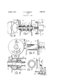
- Fig. 1 is a central longitudinal section through the reel showing the mounting of the 3U saine to an engine shaft and fly wheel,
- Fig. 2 a side elevation of the reel mounted on a stationary structure
- Fig. an enlarged partial, central, longitudinal section
- FIG. 7 an end view of said clutches. inthe use of a measuring linc reel fo-r deep wells the reel may be attached to an engine shaft as shown in Fig. 1, thereby providing u power operating means for winding the measuring line on the reel, but for a shallow well the customary method of use is to mount the reel on a stationary structure and operate tlfe same by hand, as shown in Fig. 2.
- reference character' 7 indicates a portion of a fly wheel of an engine, such fly wheel being mounted on a shaft 8, it being understood that the devices hereinafter described may be connected to any suitable power operated shaft for operating the reel.
- a disk 9 which disk has a sufficient number of holes formed about its periphery to enable the disk to be firmly secured to a fly wheel or the like in such a manner as to avoid the Wobbing that is found to occur with previous constructions. At least three such holes are provided at substantially equally spaced points about the periphery of the disk and preferably at least four holes are provided at the ends of diameters of the disk which diameters are perpendicular to each other'. rlhree such holes are shown in Fig. el and a fourth hole (not shown) is preferably arranged at the left hand end of the horizontal diameter indicated.
- a shaft l1 has one end threaded to engage a threaded aperture at the center of the disk 9, said threaded end also providing convenient means for receiving a nut 11 whereby the shaft may be secured to a fixed support 12, which nut is turned up sufficiently to bring, a collar 13 up against the fixed support.
- the collar 13 is secured to the shaft 11 by a key or in any other suitable manner.
- 'lhe reel comprises flanges 14 and 16, one of said flanges having integral therewith a substantially cylindrical hub 15 provided with friction faces at its ends.
- a tubular intermediate member or drum 17 surrounds the hub of flange 14C and is secured thereto by pins 17.
- Flange 1G has an integral hub 18 journaled on a sleeve 19 and the sleeve 17 is positively connected to the hub 18 by screws 20 which also serve to connect the hub 178 frictionally to the sleeve 19 by means of friction plugs 21 bearing on said sleeve and springs 22 interposed between the'screws 20 and-said ⁇ friction plugs.
- -A handle 23 has athreadedopening whereby it is mounted on a threaded end portion of sleeve 19, the threads being lefthanded.
- VA-collar 24 keyed-tothe-end-of shaft 11- limits the outward movement of handle 28.
- I-Iub 19 has an outwardly extending flange 25, best shown in Figs. 6 and 7, which isprovided on opposite faces with teeth adapted to engage respectively with teeth -on adjacent faces of hub 18 and of a sleeve 26.
- Thesleeve 26 is splined to shaft 11 as indicated y.at 27 so as to prevent it from turningon said shaft.
- a friction disk 28 i-s loosely mounted on shaft llbetween the other end lof sleeve 26 andthe adjacent faces of hub 15, and another ⁇ friction disk 28 is between the right hand end of hub 18 and the adjacent face of collar 13.
- the disk 9 issecured toa spoked fly wheel by an appropriate number of bolts according to the number of spokes'in the ily wheel, it being understood that it may be secured to other forms of fly wheel by providing the same with appropriate bolt holes of-suitablenumber'to permit lirm attachment of the disk, and the other Vparts are ⁇ mounted -as indicated in Fig. 1.
- Engine fly wheels are usually ⁇ made with 4-6 or 8 spokes, or in other wordsa multiple of either 3 or t, so make the disk with two sets of holes, spaced 3 in a circle and 4 in a circle which covers the complete-range.
- the circular disk provides afsafety feature as compared with former constructions in that it has' no 'projecting parts to strike -the operator.
- a reel having aftubularbody portion sur- 105 rounding the shaft, a'hub ⁇ iixe ⁇ d said'body portion, a sleeve slidable o'n the'sha'ft inside said hubclutohing means on said hub and sleeve, and means 'for moving said sleeve'endinside said tubular body havingfteeth-adapt- .120
- a reel for measuring lines and the like a shaft, spaced collars fixed to the shaft, a reel having a tubular body portion sur rounding the shaft, a hub fixed in said body portion, a sleeve slidable on the shaft inside said hub, means for clutching said hub and sleeve together for rotation, a handle, and connections between said handle and said sleeve whereby rotation of the handle in one direction serves to engage said clutching means and rotate the reel while rotation in the opposite direction disengages said clutching means.
- a reel on the second-named shaft means for connecting the reel to the second-named shaft to rotate therewith, and means for rotating the reel independently of said shafts, substantially as set forth.
- a reel for measuring lines and the like a shaft, a reel having a drum journaled di rectly thereon at one end, means for connecting the reel frictionally to said shaft for braking the reel, including friction elements within said drum, a handle for turning the reel, a clutch Within said drum for connecting the reel positively to the handle, and connections from said handle to said clutch and said friction elements whereby rotation of the handle in one direction clutches the reel positively to the handle and relieves the friction on the reel, while rotation of the handle in the opposite direction releases the reel from the handle and applies braking friction thereto, substantially as set forth.
Landscapes
- Physics & Mathematics (AREA)
- General Physics & Mathematics (AREA)
- Braking Arrangements (AREA)
Description
April 5, 1932. c:` P. HARRISON 1,852,517
REEL
Filed Nov. ll, 1929 gl w Patented Apr. 5, 1932 UNITED STATES PATENT OFFICE CHARLES P. HARRISON, F WESLEYVILLE, ElNNiYLVANIA, .ASSIGNOR TO JAREGKI MANUFACTURING CO., OF ERE, PENNSYLVANA, A CRPORAIION 0F `PENNSYL VAN 1A.
REEL
Application led November 11, 1929. Serial No. 406,431.
My said invention relates to a reel intended particularly for use with measuring lines suoli as are used on oil Wells and other deep wells, but useful also in other connections. ltis an object of my invention to provide a reel of this character with a single handle which is effective either to wind up the line or to regulate braking means for the reel.
Another object of my invention is to provide means in connection with a single handle whereby the line can be wound up by turning the handle in one direction and braking tension can be imparted to the reel or regulated by turning the handle in the other' direction.
Another object of the invention is to pro vide means whereby a single handle can be operated to give a positive locking action for windino` by turning the handle in one direc tion and a variable braking tension by turning the handle in the opposite direction.
Another object of the invention is to provide improved means for connecting the reel to power operating means therefor:
Referring to the drawings which are made a part of 'this application, and in which snnilar reference characters indicate similar parts:
Fig. 1 is a central longitudinal section through the reel showing the mounting of the 3U saine to an engine shaft and fly wheel,
Fig. 2, a side elevation of the reel mounted on a stationary structure,
Fig. 3, an end elevation of the reel when viewed from the left,
Fig. 4, an end elevation of the reel clamp when viewed from the left,
Fig. an enlarged partial, central, longitudinal section,
Fig. (i, a side elevation showing the construction of the clutches, and
Fig. 7, an end view of said clutches. inthe use of a measuring linc reel fo-r deep wells the reel may be attached to an engine shaft as shown in Fig. 1, thereby providing u power operating means for winding the measuring line on the reel, but for a shallow well the customary method of use is to mount the reel on a stationary structure and operate tlfe same by hand, as shown in Fig. 2. im In the drawings reference character' 7 indicates a portion of a fly wheel of an engine, such fly wheel being mounted on a shaft 8, it being understood that the devices hereinafter described may be connected to any suitable power operated shaft for operating the reel. ln the embodiment of the invention here illustrated a disk 9 is provided which disk has a sufficient number of holes formed about its periphery to enable the disk to be firmly secured to a fly wheel or the like in such a manner as to avoid the Wobbing that is found to occur with previous constructions. At least three such holes are provided at substantially equally spaced points about the periphery of the disk and preferably at least four holes are provided at the ends of diameters of the disk which diameters are perpendicular to each other'. rlhree such holes are shown in Fig. el and a fourth hole (not shown) is preferably arranged at the left hand end of the horizontal diameter indicated. In addition to this it is desirable to provide two holes approximately fifteen degrees distant from those at the ends of one diameter, so that bolts 10 in said holes may conveniently pass between the spokes of fly wheels having four, sii; or eight spokes and thereby support the disk firmly in all directions. In previous practice it has been usual to provide only two bolts at opposite ends of a line passing through the axis of the shaft and those of said bolts, but this gives very little support to the disk except on that line. A shaft l1 has one end threaded to engage a threaded aperture at the center of the disk 9, said threaded end also providing convenient means for receiving a nut 11 whereby the shaft may be secured to a fixed support 12, which nut is turned up sufficiently to bring, a collar 13 up against the fixed support. The collar 13 is secured to the shaft 11 by a key or in any other suitable manner.
'lhe reel comprises flanges 14 and 16, one of said flanges having integral therewith a substantially cylindrical hub 15 provided with friction faces at its ends. A tubular intermediate member or drum 17 surrounds the hub of flange 14C and is secured thereto by pins 17.
Flange 1G has an integral hub 18 journaled on a sleeve 19 and the sleeve 17 is positively connected to the hub 18 by screws 20 which also serve to connect the hub 178 frictionally to the sleeve 19 by means of friction plugs 21 bearing on said sleeve and springs 22 interposed between the'screws 20 and-said `friction plugs. -A handle 23 has athreadedopening whereby it is mounted on a threaded end portion of sleeve 19, the threads being lefthanded. l
VA-collar 24; keyed-tothe-end-of shaft 11- limits the outward movement of handle 28.
I-Iub 19 has an outwardly extending flange 25, best shown in Figs. 6 and 7, which isprovided on opposite faces with teeth adapted to engage respectively with teeth -on adjacent faces of hub 18 and of a sleeve 26. Thesleeve 26 is splined to shaft 11 as indicated y.at 27 so as to prevent it from turningon said shaft. A friction disk 28 i-s loosely mounted on shaft llbetween the other end lof sleeve 26 andthe adjacent faces of hub 15, and another` friction disk 28 is between the right hand end of hub 18 and the adjacent face of collar 13. In theuse of my device the disk 9 issecured toa spoked fly wheel by an appropriate number of bolts according to the number of spokes'in the ily wheel, it being understood that it may be secured to other forms of fly wheel by providing the same with appropriate bolt holes of-suitablenumber'to permit lirm attachment of the disk, and the other Vparts are `mounted -as indicated in Fig. 1. Engine fly wheels are usually `made with 4-6 or 8 spokes, or in other wordsa multiple of either 3 or t, so make the disk with two sets of holes, spaced 3 in a circle and 4 in a circle which covers the complete-range. The circular disk provides afsafety feature as compared with former constructions in that it has' no 'projecting parts to strike -the operator.
If it be now desiredl to `lower a measuring line into a'well under-control the handle is turned in a clockwise direction (viewed from the left in Fig 1) so `as-to cause its hub to bear against collar 24;, wherebyupon further rotation of the handle the hub 19 will move to the right since it is held frictionally 3^ against rotation with the handle by meansof friction `plugs 21 and is additionally held against rotation Iby engagement of the opposed teeth Yon flange 25 and sleeve 26 when said teeth come into engagement. This forces sleeve 26 toward hub 15 with the result that the reel is moved to the right so as to clamp the two friction disks 28 under equal tension between the opposed faces of the adjacentparts. In this way a suitable tension may be placed on the reel to permit the measuring line to unwind at the desired speed'.
VW'hen the line is to be wound up vbypower the handle is turned further inra clockwise directiony to move the sleeve "19 to the right vand clamp the friction disks tight between jacent parts.
lturned I in counterclockwise direction to lock @the-reeltof-the handle andrelease'the engagement between the friction disks and the ad- The sleeve and handle being locked together and the friction disks being loose 'the 'reel isfreetotturn with the handle. lIt will be obviousto those skilled in the art. that various otherfmodifications may .be made in my device without departing from the spirit of my invention and, therefore,'I.do not limit m -self to whatiis shown in the draw ings and cescribed in the specilication'but only as set forth in the appended claims.
IHaving thus fully described mysaid invention,what `I claim asnew and desire to secure by 'Letters`Patent, is
1. In a reelfor measuring lines and the like, a shaft, spaced collarsV fixed tothe shaft, -a reel having a tublar'body portion surrounding the shaft, a hub'fixed in said body portion,` a sleeve slidable on'the shaft inside said bodyportion, yfriction means atopposite ends of the hub adaptedto engage'respectively with said sleeveand with onef said collars, and means for moving saidreelan'd said sleeve axially of the shaft'to apply braking'friction to said reel, substantiallyas lset forth. Y n
2. Ina reel for measuring lines andthe like, a shaft, spaced collars'fizedlto the shaft,
a reel having aftubularbody portion sur- 105 rounding the shaft, a'hub `iixe`d said'body portion, a sleeve slidable o'n the'sha'ft inside said hubclutohing means on said hub and sleeve, and means 'for moving said sleeve'endinside said tubular body havingfteeth-adapt- .120
ed to engage teeth onthe firstlnamed sleeve, a hub vsurroundingggsaid llanged sleeve and secured to saidreel, clutch means on adjacent faces of said flanged sleeve and said'last- Ynamed hub, frictional connectionszbetween i said last-named hub and said Vflanged sleeve,
and a handlev having threaded engagement with a part of said flanged sleeve between one of saidy collars 4and the adjacent end of the reel whereby rotation of thehandle in opposite senses serves respectively to apply a braking friction to the reel or to clamp the reel to said handle for manual operation of the reel, substantially as set forth.
Ll. In a reel for measuring lines and the like, a shaft, spaced collars fixed to the shaft, a reel having a tubular body portion sur rounding the shaft, a hub fixed in said body portion, a sleeve slidable on the shaft inside said hub, means for clutching said hub and sleeve together for rotation, a handle, and connections between said handle and said sleeve whereby rotation of the handle in one direction serves to engage said clutching means and rotate the reel while rotation in the opposite direction disengages said clutching means.
5. The combination of a driven shaft, a ily wheel thereon, a disk at the end of the shaft and coaxial therewith said disk having bolt holes about its periphery at intervals of 90 degrees and two other bolt holes each 120 degrees distant from a bolt hole of the firstnamed set, bolts in said bolt holes connecting the disk to the fly wheel, a stationary shaft extending from said disk in coaxial relation with the disk and with said first-named shaft, said last-named shaft being held against rotation relatively to said driven shaft, a reel journaled on the second-named shaft, means for connecting the reel to the second-named shaft to rotate therewith, and means for rotating the reel independently of said shafts, substantially as set forth.
fi. The combination of a driven shaft, a fly wheel thereon, a disk at the end of the shaft and coaxial therewith said disk having bolt holes about its periphery at intervals of 120 degrees and another set of bolt holes at intervals of 90 degrees one of said holes being common to both sets, bolts in said bolt holes connecting the disk to the fly wheel, a shaft eX tending from said disk in coaxial relation with the disk and with said first-named shaft,
a reel on the second-named shaft, means for connecting the reel to the second-named shaft to rotate therewith, and means for rotating the reel independently of said shafts, substantially as set forth.
7. In a reel for measuring lines and the like, a shaft, a reel having a drum journaled di rectly thereon at one end, means for connecting the reel frictionally to said shaft for braking the reel, including friction elements within said drum, a handle for turning the reel, a clutch Within said drum for connecting the reel positively to the handle, and connections from said handle to said clutch and said friction elements whereby rotation of the handle in one direction clutches the reel positively to the handle and relieves the friction on the reel, while rotation of the handle in the opposite direction releases the reel from the handle and applies braking friction thereto, substantially as set forth.
8. The combination of a shaft, a reel rotatable thereon said reel having a hollow drum, a sleeve journaled on said shaft and extending into said drum, an abutment on said shaft, a handle threaded on said sleeve between said abutment and said reel, means between said sleeve and drum for connecting the reel positively to the handle upon rotation of the handie in one direction wherebv the reel may be rotated by the handle, braking means for the reel, and means acting through said sleeve for operating said braking means upon reverse rotation of the handle.
In testimony whereof I affix my si nature.
CHARLES P. I-IARR SON.
Priority Applications (1)
| Application Number | Priority Date | Filing Date | Title |
|---|---|---|---|
| US406431A US1852517A (en) | 1929-11-11 | 1929-11-11 | Reel |
Applications Claiming Priority (1)
| Application Number | Priority Date | Filing Date | Title |
|---|---|---|---|
| US406431A US1852517A (en) | 1929-11-11 | 1929-11-11 | Reel |
Publications (1)
| Publication Number | Publication Date |
|---|---|
| US1852517A true US1852517A (en) | 1932-04-05 |
Family
ID=23607959
Family Applications (1)
| Application Number | Title | Priority Date | Filing Date |
|---|---|---|---|
| US406431A Expired - Lifetime US1852517A (en) | 1929-11-11 | 1929-11-11 | Reel |
Country Status (1)
| Country | Link |
|---|---|
| US (1) | US1852517A (en) |
Cited By (3)
| Publication number | Priority date | Publication date | Assignee | Title |
|---|---|---|---|---|
| US2717129A (en) * | 1952-02-08 | 1955-09-06 | Seymour F Mcdonald | Portable reel |
| US3331349A (en) * | 1965-11-05 | 1967-07-18 | Oglesby Miller Dee | Boat anchor reel |
| US4065068A (en) * | 1976-10-06 | 1977-12-27 | John William Treadwell | Adding machine tape reversing rewinder |
-
1929
- 1929-11-11 US US406431A patent/US1852517A/en not_active Expired - Lifetime
Cited By (3)
| Publication number | Priority date | Publication date | Assignee | Title |
|---|---|---|---|---|
| US2717129A (en) * | 1952-02-08 | 1955-09-06 | Seymour F Mcdonald | Portable reel |
| US3331349A (en) * | 1965-11-05 | 1967-07-18 | Oglesby Miller Dee | Boat anchor reel |
| US4065068A (en) * | 1976-10-06 | 1977-12-27 | John William Treadwell | Adding machine tape reversing rewinder |
Similar Documents
| Publication | Publication Date | Title |
|---|---|---|
| US2556151A (en) | Quick detachable hub | |
| US1852517A (en) | Reel | |
| US1024344A (en) | Clutch collar. | |
| US1909420A (en) | Double-acting coil spring clutch | |
| US1503446A (en) | Shaft coupling | |
| US2727604A (en) | Winch release mechanism | |
| US1272361A (en) | Line-reel. | |
| US2286547A (en) | Power take-off attachment | |
| US2240075A (en) | Fishing reel | |
| US2546253A (en) | Collapsible spool | |
| US2185731A (en) | Transmission mechanism | |
| US1385457A (en) | Fishing-reel | |
| US1662654A (en) | Expanding pulley | |
| US2526565A (en) | Double lock core head | |
| US1270809A (en) | Portable winch. | |
| US2000959A (en) | Braking mechanism | |
| US2002979A (en) | Clutch | |
| US2525764A (en) | Safety winch | |
| US2207038A (en) | Overload clutch | |
| US971756A (en) | Motor-cycle gearing. | |
| US1170980A (en) | Transmission-gear and clutch. | |
| US2457352A (en) | Brake drum assembly | |
| US2071579A (en) | Clutch for rotary draw works | |
| US822453A (en) | Transmission-gear. | |
| US532162A (en) | lindsay |