US1852516A - Expansion joint - Google Patents
Expansion joint Download PDFInfo
- Publication number
- US1852516A US1852516A US351988A US35198829A US1852516A US 1852516 A US1852516 A US 1852516A US 351988 A US351988 A US 351988A US 35198829 A US35198829 A US 35198829A US 1852516 A US1852516 A US 1852516A
- Authority
- US
- United States
- Prior art keywords
- pipe
- studs
- ring
- diaphragms
- expansion joint
- Prior art date
- Legal status (The legal status is an assumption and is not a legal conclusion. Google has not performed a legal analysis and makes no representation as to the accuracy of the status listed.)
- Expired - Lifetime
Links
- 210000000188 diaphragm Anatomy 0.000 description 16
- 230000008602 contraction Effects 0.000 description 5
- 239000000463 material Substances 0.000 description 4
- 229910000851 Alloy steel Inorganic materials 0.000 description 1
- RYGMFSIKBFXOCR-UHFFFAOYSA-N Copper Chemical compound [Cu] RYGMFSIKBFXOCR-UHFFFAOYSA-N 0.000 description 1
- 238000010276 construction Methods 0.000 description 1
- 229910052802 copper Inorganic materials 0.000 description 1
- 239000010949 copper Substances 0.000 description 1
- 238000007689 inspection Methods 0.000 description 1
- 230000003014 reinforcing effect Effects 0.000 description 1
Images

Classifications
-
- F—MECHANICAL ENGINEERING; LIGHTING; HEATING; WEAPONS; BLASTING
- F16—ENGINEERING ELEMENTS AND UNITS; GENERAL MEASURES FOR PRODUCING AND MAINTAINING EFFECTIVE FUNCTIONING OF MACHINES OR INSTALLATIONS; THERMAL INSULATION IN GENERAL
- F16L—PIPES; JOINTS OR FITTINGS FOR PIPES; SUPPORTS FOR PIPES, CABLES OR PROTECTIVE TUBING; MEANS FOR THERMAL INSULATION IN GENERAL
- F16L51/00—Expansion-compensation arrangements for pipe-lines
- F16L51/02—Expansion-compensation arrangements for pipe-lines making use of a bellows or an expansible folded or corrugated tube
- F16L51/025—Expansion-compensation arrangements for pipe-lines making use of a bellows or an expansible folded or corrugated tube with several corrugations
- F16L51/029—Expansion-compensation arrangements for pipe-lines making use of a bellows or an expansible folded or corrugated tube with several corrugations consisting of flexible rings
Definitions
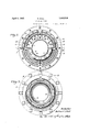
- Series of backing plates 12 are provided for each of the diaphragms 9, these backing plates being supported at their inner edges in an annular depression 13 formed in the pipe studs 1 and 2 and in the center ring i. At their outer edges, the backing plates are supported in recesses 111 formed at the top of the side Walls 6.
- Each of the baclring plates of a series is oi substantially keystone shape, as clearly illustrated in Fig. 2, and the adjacent plates are maintained in proper spaced relation by means of pins 'i5 Which are rigidly secured in the pipe studs, the center ring 4, and in the side Walls 6 of the respective casings.
- the flexible diaphragme 9 assume a more orV less conical or frusto-conical form, and that this iorm varies in accordance With the expansion or contraction of the pipe line.
- the diaphragms are therefore constantly subjected tof fleXures, by reason of which their formV is varied, and it is therefore necessary that the diaphragms be made of material which Will withstand a great number of such iexures.
- diaphragms made of heatand cor-rosion-resisting material such as nickel-steel alloys, are hivhly satisfactory for this purpose, and that diaphragme oi such material will out-last in service diaphragms oi copper or other ducti-le material heretoforeV employed.
- the backing plates 12 form a support for f the diaphragms- 9, but they are not suiicient to relieve the strain on the diaphragm caused by their constantY iiexure. I have therefore provided additional. reinforcing means in the form of; concentric rings 16-Which are interposed; between the backing plates 12 and the diaphra'gms 9, andwhich rings fit intl e corrugations of the diaphragme.
- an object oi the invention is to provide an expansion joint in WhichV any number of flexible diaphragms may be employed and in which means are provided for limiting the-movement' of each of said' dfiaaphragms so that all oi the eXpansi-on or contraction in the pipe line is not l taken up; by only one ci"l the diaphragms butv is equa-lilyy distributed to all of them.
- the casings 5, the pipe studs 1 and 2 and the center ring 4 are provided With suitable stops for limitingv the movement off the diaphragms-.- As Will be seen from an inspection of Fig.
- the pipe studs 1 and 2 are provided with stop rings 17 and 18. These rings may be either continuous or may be notched as indicated in Fig. 3.
- the side Wall 6 of each of the casings 5 Which surrounds the pipe studs 1 lor 2 is located between the stops 17 and 18, and its inside periphery 20 may be notched similarly to the rings 17 and 18. This arrangement is made for the purpose of ease in assembl-ing will be noted that the adjacent side Walls 6 l of the respective casings 5 are located between the center stop ring 19 and theouter stop rings 21.
- An expansion joint for pipe lines subjected to varying temperatures including a pair of pipe studs, a pipe section secured to one of said pipe studs and telescoping in the other, a ring surrounding said pipe section, vcasings having side walls interposed between said ring and said pipe studs, eXible diaphragms in said easings, and means to limit movement of said diaphragme, said means including pairs of stops on said ring and said pipe studs, said stopscomprising projections and notches, the inner periphery of the side walls of said casings surrounding said ring and said pipe studs and being provided with projections and notchessimilar to said stops, whereby the projections on the side walls reoister with the projections on said stops anc are Confined therebetween.
Landscapes
- Engineering & Computer Science (AREA)
- General Engineering & Computer Science (AREA)
- Mechanical Engineering (AREA)
- Joints Allowing Movement (AREA)
Description
April 5, 1932. 1,852,516
R. HALL EXPANS ION- JOINT April 5, 1932. R. HALL EXPANSION JOINT z sheets-sheet '2 Filed April 2. 1929 Rob erf H6217 diaphragms surrounds the pipe section 3 and is secured to the pipe studs or the center ring Li, as the case may be, by means of annular securing members 10 Which are rigidly connected to the pipe studs or center ring 4l by means of bolts 11. The diaphragms are provided With apertures for' the passage oi the said bolts l1, as is clearly illustrated in Fig. 1.
Series of backing plates 12 are provided for each of the diaphragms 9, these backing plates being supported at their inner edges in an annular depression 13 formed in the pipe studs 1 and 2 and in the center ring i. At their outer edges, the backing plates are supported in recesses 111 formed at the top of the side Walls 6. Each of the baclring plates of a series is oi substantially keystone shape, as clearly illustrated in Fig. 2, and the adjacent plates are maintained in proper spaced relation by means of pins 'i5 Which are rigidly secured in the pipe studs, the center ring 4, and in the side Walls 6 of the respective casings.
In the operation of an expansion joint'o this type, it is of course understood that the flexible diaphragme 9 assume a more orV less conical or frusto-conical form, and that this iorm varies in accordance With the expansion or contraction of the pipe line. The diaphragms are therefore constantly subjected tof fleXures, by reason of which their formV is varied, and it is therefore necessary that the diaphragms be made of material which Will withstand a great number of such iexures. I have found that, in actual practice, diaphragms made of heatand cor-rosion-resisting material, such as nickel-steel alloys, are hivhly satisfactory for this purpose, and that diaphragme oi such material will out-last in service diaphragms oi copper or other ducti-le material heretoforeV employed.
The backing plates 12 'form a support for f the diaphragms- 9, but they are not suiicient to relieve the strain on the diaphragm caused by their constantY iiexure. I have therefore provided additional. reinforcing means in the form of; concentric rings 16-Which are interposed; between the backing plates 12 and the diaphra'gms 9, andwhich rings fit intl e corrugations of the diaphragme.
As hereto-fore stated, an object oi the invention is to provide an expansion joint in WhichV any number of flexible diaphragms may be employed and in which means are provided for limiting the-movement' of each of said' dfiaaphragms so that all oi the eXpansi-on or contraction in the pipe line is not l taken up; by only one ci"l the diaphragms butv is equa-lilyy distributed to all of them. For this purpose-, the casings 5, the pipe studs 1 and 2 and the center ring 4 are provided With suitable stops for limitingv the movement off the diaphragms-.- As Will be seen from an inspection of Fig. 1, the pipe studs 1 and 2 are provided with stop rings 17 and 18. These rings may be either continuous or may be notched as indicated in Fig. 3. The side Wall 6 of each of the casings 5 Which surrounds the pipe studs 1 lor 2 is located between the stops 17 and 18, and its inside periphery 20 may be notched similarly to the rings 17 and 18. This arrangement is made for the purpose of ease in assembl-ing will be noted that the adjacent side Walls 6 l of the respective casings 5 are located between the center stop ring 19 and theouter stop rings 21.
From the construction just described, it is believed that the ope-ration of my device will be clear, particularly With reference tothe equal distribution of the expansion in the line upon the several flexible diaphra-gms 9. Upon expansion in the line, the pipe studs 1 and 2 will move towards each other, thus permitting the pipe 3 to telescope further into the pipe stud 2. Such movement continues until the stop rings 17 contact With the side Walls 6 of the casings. Similar movement takes place at the other .side of the casing, until the side wall 6 contacts with the center stop 19- on' the ring 4., Upon contraction, the opposite action takes place; that is to say, the pipe studs 1 and 2 separate and such movement continues until the stop rings 18 contact with the side Walls 6', thus eiiectually limiting the amount of movement of the flexible diaphragms 9 and distributing the expansion or contraction of the pipe equally on all of the i diaphragme.
While I have illustrated inthe drawings an expansion joint which includes two casingsin each of which is located a pair of flexible diaphragme, it will now be understood that any` desired number of such casings may bo joined in series. For this purpose, acenter ring similar to the ringei may be substituted for either one of the pipe studs 1 and 2,'a casing similar to the casing 5 is then inserted adjacent the said ring, and then a pipe stud. Bv this arrangement', therefore, an; exp ansion: joint including any number of flexible diaphragms may be constructed and by reason of the provision of the stops heretofore described, it Will be understod that the amount oi' expansion or contraction of the pipe will' be compensated for by equal distribution thereof upon all ot the diaphragme. It will readily be appreciated by those skilled inthe art that, by such anY arrangement, all of the to said casings, means to secure the inner periphery of one of the diaphragms of each pair' to one of said pipe studs, and means to securev the inner peripher'y of the other diaphragm to said' ring.
l0. An expansion joint for pipe lines subjected to varying temperatures, including a pair of pipe studs, a pipe section secured to one of said pipe studs and telescoping in the other, a ring surrounding said pipe section, vcasings having side walls interposed between said ring and said pipe studs, eXible diaphragms in said easings, and means to limit movement of said diaphragme, said means including pairs of stops on said ring and said pipe studs, said stopscomprising projections and notches, the inner periphery of the side walls of said casings surrounding said ring and said pipe studs and being provided with projections and notchessimilar to said stops, whereby the projections on the side walls reoister with the projections on said stops anc are Confined therebetween.
l1. In an expansion joint, a pair of pipe studs, a pipe section secured to one of said pipe'y studs and telescop-ing in the other, a ring surrounding said pipe section, and. casings sllid'ably mounted on said' pipe studs and said ring.
12. In an expansion joint, a pair of pipe studs, a pipe section secured to one of said pipe studs and teleseo'ping in. the other, a ring surrounding said pipe section, oasings sllidably mounted on said pipe studs and said rin-g, and means on said pipe studs andV said ring for limiting the sliding movement of said casings.
I3. In an expansion joint, a pair of pipe Studs, a pipe section secured to one of said pipe studs and telescoping in the other, a ring surrounding said pipe section, pairs of stops on said ring and said pipe studs, and casings surrounding said pipe studs and said ring and havingside walls confined between the stops of said pairs. j
In testimony whereof I, aiix my signature.
ROBERT HALL.
Priority Applications (1)
| Application Number | Priority Date | Filing Date | Title |
|---|---|---|---|
| US351988A US1852516A (en) | 1929-04-02 | 1929-04-02 | Expansion joint |
Applications Claiming Priority (1)
| Application Number | Priority Date | Filing Date | Title |
|---|---|---|---|
| US351988A US1852516A (en) | 1929-04-02 | 1929-04-02 | Expansion joint |
Publications (1)
| Publication Number | Publication Date |
|---|---|
| US1852516A true US1852516A (en) | 1932-04-05 |
Family
ID=23383302
Family Applications (1)
| Application Number | Title | Priority Date | Filing Date |
|---|---|---|---|
| US351988A Expired - Lifetime US1852516A (en) | 1929-04-02 | 1929-04-02 | Expansion joint |
Country Status (1)
| Country | Link |
|---|---|
| US (1) | US1852516A (en) |
-
1929
- 1929-04-02 US US351988A patent/US1852516A/en not_active Expired - Lifetime
Similar Documents
| Publication | Publication Date | Title |
|---|---|---|
| US2232936A (en) | Expansion joint | |
| US2009650A (en) | Pipe joint | |
| US1852516A (en) | Expansion joint | |
| US1625541A (en) | Elastic-fluid turbine | |
| US2599210A (en) | Internally insulation lined vessel | |
| US1887081A (en) | Coupling | |
| US2643078A (en) | Elastic fluid turbine support | |
| US1622101A (en) | Flexible coupling | |
| US1558139A (en) | Heat-exchange apparatus | |
| US1660163A (en) | Surface condenses | |
| US1662006A (en) | Flexible coupling | |
| US2089026A (en) | Temperature compensated retort end | |
| US1787086A (en) | Heat interchanger | |
| US1832637A (en) | Condenser | |
| US2487410A (en) | Flexible joint | |
| SU101603A1 (en) | Rotary kiln heat exchanger | |
| US1322128A (en) | ludeman | |
| US1626869A (en) | Expansion joint for heat exchangers | |
| US2648315A (en) | Boiler furnace wall construction | |
| US2384410A (en) | Mounting for electron tubes | |
| US1862515A (en) | Casing for outside steam pipes | |
| US1449701A (en) | Sealing head | |
| US1804647A (en) | Controller drum | |
| US1630733A (en) | Thermostat diaphragm | |
| US2523318A (en) | Balloon type gasholder |