US1852511A - Bottom construction for bedsprings and the like - Google Patents
Bottom construction for bedsprings and the like Download PDFInfo
- Publication number
- US1852511A US1852511A US230664A US23066427A US1852511A US 1852511 A US1852511 A US 1852511A US 230664 A US230664 A US 230664A US 23066427 A US23066427 A US 23066427A US 1852511 A US1852511 A US 1852511A
- Authority
- US
- United States
- Prior art keywords
- spring
- springs
- upright
- side rails
- bed
- Prior art date
- Legal status (The legal status is an assumption and is not a legal conclusion. Google has not performed a legal analysis and makes no representation as to the accuracy of the status listed.)
- Expired - Lifetime
Links
- 238000010276 construction Methods 0.000 title description 4
- 238000007665 sagging Methods 0.000 description 6
- 238000004519 manufacturing process Methods 0.000 description 2
- 239000000463 material Substances 0.000 description 2
- 230000000284 resting effect Effects 0.000 description 2
- 230000035807 sensation Effects 0.000 description 2
- 239000004744 fabric Substances 0.000 description 1
Images
Classifications
-
- A—HUMAN NECESSITIES
- A47—FURNITURE; DOMESTIC ARTICLES OR APPLIANCES; COFFEE MILLS; SPICE MILLS; SUCTION CLEANERS IN GENERAL
- A47C—CHAIRS; SOFAS; BEDS
- A47C23/00—Spring mattresses with rigid frame or forming part of the bedstead, e.g. box springs; Divan bases; Slatted bed bases
- A47C23/04—Spring mattresses with rigid frame or forming part of the bedstead, e.g. box springs; Divan bases; Slatted bed bases using springs in compression, e.g. coiled
- A47C23/05—Frames therefor; Connecting the springs to the frame ; Interconnection of springs, e.g. in spring units
Definitions
- This invention relates broadly to improvements in bed springs and bed bottoms, and more particularly to springs of the upright spiral-helical type.
- the main object of the invention is to pro vide greater resiliency near the ends of the spring where but little weight is carried than at the centre where the greater part of the weight is carried, thereby to eliminate centrally localized sagging in use.
- the resiliency of the ends is increased, so that the spring yields at the ends to approximately the same extent as it yields in the centre. In this way, back straining sagging is eliminated and the spring becomes more comfortable to sleep on, by reason of resiliency at the ends instead of rigidity.
- the result is obtained by use of flexible or resilient bottom supports for the upright coils toward the ends of the spring, while rigid bottom supports are used in the central part of the structure. If desired, the upright coils resting on the flexible supports may be more resilient than the coils resting 011 the rigid supports but, ordinarily, this is not necessary and from a manufacturing point of View is not desirable.
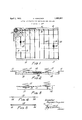
- FIG. 1 is a plan view of a bed spring bot tom formed according to the invention.
- Fig. 2 is a fragmentary transverse sectional view of the spring bottom at the line 2-2 of Figure l, on an enlarged scale.
- Fig. 3 is a fragmentary longitudinal sectional view on the line 33 of Figure 1 and on the same scale as Figure 2.
- Figs. 4 and 5 illustrate various forms of resilient coil supports.
- 11 designates the side rails of a bed spring bottom, which are of any suitable material and cross section
- 12 designates a series of rigid transverse members of any suitable material and cross section connected between the side rails at the ends and at the central parts thereof.
- resilient and preferably flexible transverse members 13 are connected between the side rails. While only one resilient member 13 has been shown toward each end of the spring bottom, it will be 7 understood that the number may be increased as necessary or desirable.
- the resilient members may of forms of which the most simple is illustrated in Figure 1,11amely, a spring wire connected at its ends to the side rails and formed in its central part into a helical spring 14. While only one spring is shown in the length of the support, it will be understood that the number and arrangement of the springs may as be varied as desired, for example, as shown in Figure 4, wherein springs are formed toward both ends of the support leaving the centre plain. In any wire support the spring or springs 14 may be formed integral with the wire or otherwise, as desired.
- a further form of resilient support is shown in Figure 5 and includes a bar 15 and springs 16 at the ends thereof to resiliently support the bar between the side rails. The springs 16 may be connected to the bar 15 and to the side rails in any way desired.
- the upright spring units 17 of the bed spring rest upon the supports 12 and 13 and are tied thereto in any usual or suitable mantake a variety ner, for example, by locking wires 18 extending longitudinally of the bottom frame.
- a great advantage of the present invention is that in its simple forms, it reducesthe cost ofbed springs and may therefore be'app'lied equally-to the cheapest and to the most expensive springs and to upright coil springs of all types, whereas efiorts formerly made to stiffen springs against sagging added materially to the cost and were therefore not applicable to cheaper grades of springs.
- While the invention relates primarily to bed springs-of the upright coil-type, it is applicable in principle to and extends to other types of bed bottoms, particularly .side supported fabric bottoms.
- a bed spring comprising side rails
- rigid members rigidly connected to the (1e11 .tral parts of said side rails ;and.extending transversely from rail :to rail and flexible wires including helical springs connected .to the rails toward the ends thereofand extending transversely from rail to railiand-upright spring unit supported on said rigid' and flexible members and means connecting the tops of said upright c011 springs.
- said wires including helically formed spring portions and upright ,coil springs supported on :said bars and wires and means connecting the .tops of said upright coil springs.
Landscapes
- Springs (AREA)
- Mattresses And Other Support Structures For Chairs And Beds (AREA)
Description
April 5, 1932. R. FERGUSON 1,852,511
BOTTOM CONSTRUCTION FOR BEDSPRINGS AND THE LIKE Filed Nov. 2, 1927 All A l 4 F76. 4 //7Ve/7/0r Fey/haw Feryason /6 E6; 5 /6 flew),
i atentecl Apr. 5, 1932 UNITED STATES PATENT OFFICE REGINALD FERGUSON, OI MONTREAL, QUEBEC, CANADA, ASSIGNOR TO SIMMONS LIMITED, 01' MONTREAL, QUEBEC, CANADA BOTTOM CONSTRUCTION FOR BEDSPRINGS AND THE LIKE Application filed November 2, 1927. Serial No. 230,664.
This invention relates broadly to improvements in bed springs and bed bottoms, and more particularly to springs of the upright spiral-helical type.
The main object of the invention is to pro vide greater resiliency near the ends of the spring where but little weight is carried than at the centre where the greater part of the weight is carried, thereby to eliminate centrally localized sagging in use.
In the manufacture of bed springs of the upright coil type, the aim heretofore has been to make the spring bottom upon which the upright coils rest such as to give uni formly rigid support to the coils. Departure from this aim has been in the direction of less rigidity at the centre of the spring due to yielding of the spring bottom when under load and has been avoided as far as possible owing to the disadvantage that it induces a central sag in the spring top. WVhen sufiiciently rigid bottom construction and sufiiciently stiff coils are used to avoid excessive sagging in the centre where the greatest weight is carried, the ends of the spring where but little weight is carried are lacking in resiliency and the efiect or sensation is much the same as if an excessive sag existed.
According to this invention, instead of stiiiening the centre part of the spring, the resiliency of the ends is increased, so that the spring yields at the ends to approximately the same extent as it yields in the centre. In this way, back straining sagging is eliminated and the spring becomes more comfortable to sleep on, by reason of resiliency at the ends instead of rigidity. The result is obtained by use of flexible or resilient bottom supports for the upright coils toward the ends of the spring, while rigid bottom supports are used in the central part of the structure. If desired, the upright coils resting on the flexible supports may be more resilient than the coils resting 011 the rigid supports but, ordinarily, this is not necessary and from a manufacturing point of View is not desirable.
In the drawings which illustrate one embodiment of the invention but to the details of which the invention is not confined Fig. 1 is a plan view of a bed spring bot tom formed according to the invention.
Fig. 2 is a fragmentary transverse sectional view of the spring bottom at the line 2-2 of Figure l, on an enlarged scale.
Fig. 3 is a fragmentary longitudinal sectional view on the line 33 of Figure 1 and on the same scale as Figure 2.
Figs. 4 and 5 illustrate various forms of resilient coil supports.
Referring more particularly to the draW ings, 11 designates the side rails of a bed spring bottom, which are of any suitable material and cross section, and 12 designates a series of rigid transverse members of any suitable material and cross section connected between the side rails at the ends and at the central parts thereof. Toward the ends of the bottom frame, resilient and preferably flexible transverse members 13 are connected between the side rails. While only one resilient member 13 has been shown toward each end of the spring bottom, it will be 7 understood that the number may be increased as necessary or desirable.
The resilient members may of forms of which the most simple is illustrated in Figure 1,11amely, a spring wire connected at its ends to the side rails and formed in its central part into a helical spring 14. While only one spring is shown in the length of the support, it will be understood that the number and arrangement of the springs may as be varied as desired, for example, as shown in Figure 4, wherein springs are formed toward both ends of the support leaving the centre plain. In any wire support the spring or springs 14 may be formed integral with the wire or otherwise, as desired. A further form of resilient support is shown in Figure 5 and includes a bar 15 and springs 16 at the ends thereof to resiliently support the bar between the side rails. The springs 16 may be connected to the bar 15 and to the side rails in any way desired.
The upright spring units 17 of the bed spring rest upon the supports 12 and 13 and are tied thereto in any usual or suitable mantake a variety ner, for example, by locking wires 18 extending longitudinally of the bottom frame.
When a person lies upon the spring, the rigidly supported upright spring units in the central part Where the greatest load is located are compressed and the spring top (not shown) tends to sag in the centre. The resiliently supported upright spring units under the sleepers head and feet are somewhat compressed and are 'in addition "moved bodily downward as the supports yiel d with the result that the spring top .is pressed downward at the head andfoo't of the spring to approximately the same extent as the central part. The usual sensation of a sagged spring is not experienced, because the sag has been extended under the sleepers whole body instead ofbeing concentrated .underithe trunk. In this way, the .much desired restfulfeeling of lying-on a level surface isexperienced,together with the comfort of lying-on a freely resilient spring. It will thus be seen that, instead of opposing the central sagging with uncomfortably rigid structures, the central part of the springis allowed-to sagvaud'the sagging is invited at orextended to the iQIldS of the spring.
A great advantage of the present invention is that in its simple forms, it reducesthe cost ofbed springs and may therefore be'app'lied equally-to the cheapest and to the most expensive springs and to upright coil springs of all types, whereas efiorts formerly made to stiffen springs against sagging added materially to the cost and were therefore not applicable to cheaper grades of springs.
tral parts of said side rails, wires connected to and extending between the side rails toward the ends thereof, said wires including helically formed spring portions, upright coil springs mounted on said bars and wires, and locking wires binding the-coilsprings to the bars and first named wires .and means connecting the tops of said upright coil springs.
In Witness whereof, I have hereunto set my hand. r REGINALD FERGUSON.
While the invention relates primarily to bed springs-of the upright coil-type, it is applicable in principle to and extends to other types of bed bottoms, particularly .side supported fabric bottoms.
Having thus described my invention, What I claim is 2-.-
.1. A bed spring comprising side rails,
rigid members rigidly connected to the (1e11 .tral parts of said side rails ;and.extending transversely from rail :to rail and flexible wires including helical springs connected .to the rails toward the ends thereofand extending transversely from rail to railiand-upright spring unit supported on said rigid' and flexible members and means connecting the tops of said upright c011 springs.
2. A bed spring compr1s1ng side.ra1ls,,flat
bars disposed edge up and rigidly connected "to the central parts of said side rails,
and wires connected to the side rails toward the :ends thereof, said wires including helically formed spring portions and upright ,coil springs supported on :said bars and wires and means connecting the .tops of said upright coil springs.
3. .In a bed spring, the-'combinationiof side -rails,fflat bars 'disposedaedget up and rigidly connected to. and extending between the-cen-
Priority Applications (1)
| Application Number | Priority Date | Filing Date | Title |
|---|---|---|---|
| US230664A US1852511A (en) | 1927-11-02 | 1927-11-02 | Bottom construction for bedsprings and the like |
Applications Claiming Priority (1)
| Application Number | Priority Date | Filing Date | Title |
|---|---|---|---|
| US230664A US1852511A (en) | 1927-11-02 | 1927-11-02 | Bottom construction for bedsprings and the like |
Publications (1)
| Publication Number | Publication Date |
|---|---|
| US1852511A true US1852511A (en) | 1932-04-05 |
Family
ID=22866107
Family Applications (1)
| Application Number | Title | Priority Date | Filing Date |
|---|---|---|---|
| US230664A Expired - Lifetime US1852511A (en) | 1927-11-02 | 1927-11-02 | Bottom construction for bedsprings and the like |
Country Status (1)
| Country | Link |
|---|---|
| US (1) | US1852511A (en) |
-
1927
- 1927-11-02 US US230664A patent/US1852511A/en not_active Expired - Lifetime
Similar Documents
| Publication | Publication Date | Title |
|---|---|---|
| US149758A (en) | Improvement | |
| US399867A (en) | Woven-wire mattress | |
| US1852511A (en) | Bottom construction for bedsprings and the like | |
| US1297088A (en) | Adjustable back-rest. | |
| US2120093A (en) | Spring filling construction for mattresses and cushions | |
| US2061725A (en) | Studio couch | |
| US1866664A (en) | Spring construction | |
| US564531A (en) | Couch | |
| US120587A (en) | Improvement in bed-bottoms | |
| US160185A (en) | Improvements in bed-bottoms | |
| US1594276A (en) | Bedspring | |
| US2836836A (en) | Contour mattress | |
| US1880137A (en) | Spring cushioned upholstery | |
| US749901A (en) | Mattress | |
| US1994901A (en) | Bed bottom | |
| US1431976A (en) | Attachment for bedsprings | |
| US762536A (en) | Elastic bed-bottom. | |
| US1768189A (en) | Bedspring | |
| US1943067A (en) | Coiled spring structure | |
| US1678400A (en) | Spring cushion | |
| US630967A (en) | Couch. | |
| US978954A (en) | Spring-mattress frame. | |
| US2059424A (en) | Spring cushion | |
| US1261258A (en) | Bed and couch spring. | |
| US739360A (en) | Spring bed-bottom. |