US1852498A - Internal combustion engine - Google Patents
Internal combustion engine Download PDFInfo
- Publication number
- US1852498A US1852498A US287963A US28796328A US1852498A US 1852498 A US1852498 A US 1852498A US 287963 A US287963 A US 287963A US 28796328 A US28796328 A US 28796328A US 1852498 A US1852498 A US 1852498A
- Authority
- US
- United States
- Prior art keywords
- crank case
- cylinders
- bands
- cylinder
- engine
- Prior art date
- Legal status (The legal status is an assumption and is not a legal conclusion. Google has not performed a legal analysis and makes no representation as to the accuracy of the status listed.)
- Expired - Lifetime
Links
- 238000002485 combustion reaction Methods 0.000 title description 18
- 239000002360 explosive Substances 0.000 description 9
- 238000004880 explosion Methods 0.000 description 6
- 230000006835 compression Effects 0.000 description 5
- 238000007906 compression Methods 0.000 description 5
- 238000002347 injection Methods 0.000 description 5
- 239000007924 injection Substances 0.000 description 5
- 239000004449 solid propellant Substances 0.000 description 5
- 238000000034 method Methods 0.000 description 3
- 239000000203 mixture Substances 0.000 description 3
- 229910000737 Duralumin Inorganic materials 0.000 description 1
- XAGFODPZIPBFFR-UHFFFAOYSA-N aluminium Chemical compound [Al] XAGFODPZIPBFFR-UHFFFAOYSA-N 0.000 description 1
- 229910052782 aluminium Inorganic materials 0.000 description 1
- 238000005266 casting Methods 0.000 description 1
- 238000010276 construction Methods 0.000 description 1
- 238000005192 partition Methods 0.000 description 1
- 230000003014 reinforcing effect Effects 0.000 description 1
- 239000007858 starting material Substances 0.000 description 1
Images

Classifications
-
- F—MECHANICAL ENGINEERING; LIGHTING; HEATING; WEAPONS; BLASTING
- F02—COMBUSTION ENGINES; HOT-GAS OR COMBUSTION-PRODUCT ENGINE PLANTS
- F02F—CYLINDERS, PISTONS OR CASINGS, FOR COMBUSTION ENGINES; ARRANGEMENTS OF SEALINGS IN COMBUSTION ENGINES
- F02F1/00—Cylinders; Cylinder heads
- F02F1/02—Cylinders; Cylinder heads having cooling means
- F02F1/04—Cylinders; Cylinder heads having cooling means for air cooling
- F02F1/045—Attachment of cylinders to crankcase
-
- F—MECHANICAL ENGINEERING; LIGHTING; HEATING; WEAPONS; BLASTING
- F02—COMBUSTION ENGINES; HOT-GAS OR COMBUSTION-PRODUCT ENGINE PLANTS
- F02B—INTERNAL-COMBUSTION PISTON ENGINES; COMBUSTION ENGINES IN GENERAL
- F02B75/00—Other engines
- F02B75/16—Engines characterised by number of cylinders, e.g. single-cylinder engines
- F02B75/18—Multi-cylinder engines
- F02B75/22—Multi-cylinder engines with cylinders in V, fan, or star arrangement
- F02B75/222—Multi-cylinder engines with cylinders in V, fan, or star arrangement with cylinders in star arrangement
-
- F—MECHANICAL ENGINEERING; LIGHTING; HEATING; WEAPONS; BLASTING
- F02—COMBUSTION ENGINES; HOT-GAS OR COMBUSTION-PRODUCT ENGINE PLANTS
- F02F—CYLINDERS, PISTONS OR CASINGS, FOR COMBUSTION ENGINES; ARRANGEMENTS OF SEALINGS IN COMBUSTION ENGINES
- F02F7/00—Casings, e.g. crankcases
- F02F7/0002—Cylinder arrangements
- F02F7/0017—Crankcases of radial engines
-
- F—MECHANICAL ENGINEERING; LIGHTING; HEATING; WEAPONS; BLASTING
- F05—INDEXING SCHEMES RELATING TO ENGINES OR PUMPS IN VARIOUS SUBCLASSES OF CLASSES F01-F04
- F05C—INDEXING SCHEME RELATING TO MATERIALS, MATERIAL PROPERTIES OR MATERIAL CHARACTERISTICS FOR MACHINES, ENGINES OR PUMPS OTHER THAN NON-POSITIVE-DISPLACEMENT MACHINES OR ENGINES
- F05C2201/00—Metals
- F05C2201/02—Light metals
- F05C2201/021—Aluminium
Definitions
- This invention relates to internal combustion engines.
- the principal object of this invention is to provide improved means for securing the cylinders to the crank case of engines of the ra dial, opposed cylinder or related types. More particularly tension band means encircling the crank case in close proximity thereto are provided to fasten the cylinders to the crank case.
- the band means of the present invention eliminates the usual fastening bolts or similar threaded means and absorbs the recurring tensile loads resulting from the expansion of the explosive mixture during operation of the engine thus relievin the crank case of these relative high tensile stresses to which it would be subjected were bolts used. These loads are distributed uniformly around the 1928. Serial No. 287,963.
- crank case which is sion by the band means.
- the bands are of minimum'length and weight. They create practically no wind resistance.
- the cylinders may be made light in weight as the bands impose no stresses on them.
- the flanges on the cylinders are held uniformly against their seats on the crank case thus maintaining the cylinders in exact radial alignment and eliminating localized stresses on the flanges.
- Another object of this invention is to form the tension bands in sections and connect the same by adjustable means which permit the bands to be properly tensioned and also afford ready assembly and disassembly of the cylinders and crank case.
- Fig. 1 is a front elevation, with parts broken away, of an internal combustion engine embodying the present invention
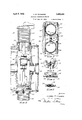
- Fig. 2 is a sectional view of the engine, wfitip parts broken away, taken on line 2-2 0 ig. 1;
- Fig. 3 is a sectional view taken on line 3-3 of Fig. 1;
- Fig. 4 is a sectional view taken on line 44 of Fig. 3;
- Fig. 5 is a sectional view taken on line 55 of Fig. 3, and
- Fig. 6 is a sectional view taken on line 6-6 of Fi 3.
- 10 represents generally a nine cylinder radial internal combustion engine of the compression-ignition or solid fuel injection type embodying the present invention.
- the engine has a crank case 11 of substantially cyllndrical form, provided with an integral diaphragm placed under compres- 12 and a removable diaphragm 13 secured by suitable means on the inside of the crank case.
- a crank shaft 1 1 Mounted in suitable bearings in the diaphragms 12 and 13 is a crank shaft 1 1, having a crank 15 upon which are journalled connecting rods 16 connecting the pistons of the engine to the crank shaft.
- the diaphragms define a plurality of relatively isolated compartments in the crank case, the central one of which houses the crank and rods.
- a removable cover 17 secured in position by any suitable means closes the open anti-propeller end of the crank case, the cover being provided with an opening 18 through which the driving shaft of the engine starter, not shown, projects.
- a propeller hub 19 is non-rotatably secured in any suitable manner on the forward end of the crank shaft.
- the engine has separately formed cylinders 20, each provided with a laterally projecting flange 21 adjacent its lower open end.
- the flange 21 is provided, on the side facing the cylinder head, .
- the circumferential part of the crank case is provided with spaced openings 24. adapted to receive the projecting ends 25 of the cylinders and surrounding or adjacent each of these openings 24, the crank case is preferably flat to provide a plane seat 26 for the cylinder flanges 21.
- the cylinders are removably secured in radial position on the crank case by two continuous bands 27 of preferably circular cross section positioned in the grooves 22 of each cylinder flange and extending around the crank case.
- Each of the bands 27 is preferably formed in three sections, as shown, the ends of the sections being threaded and connected by suitable turnbuckles 28.
- the portions of the bands 27 adapted to be positioned in the cylinder flange grooves 22 are preferably arcuately formed to correspond with the curvature of the grooves 22, and those portions adapted to be positioned between the cylinder flanges 21 are preferably formed straight, as shown.
- an auxiliary fastening means for the cylinders is employed.
- This auxiliary fastening means comprises lugs 29 adapted to engage the projecting portions 23 of adjacent cylinders and to be removably secured in position by bolts 30 or other suitable means engaging the crank case.
- the bands 27, the sections of which have previously been connected by the turnbuckles 28, are slipped over the cylinder flanges 21, into the flange grooves 22, after which the turnbuckles are rotated to contract or tighten the bands about the cylinder flanges and thus securely hold the cylinders in position on the crank case.
- the turnbuckles are rotated in the opposite direction to expand or loosen the bands sufliciently to permit them to be slipped off the cylinder flanges.
- the diaphragms 12 and 13 are preferably so located or positioned in the crank case that their peripheries will lie in the plane of the bands 27 when in position, although it will be apparent that they may be positioned at one side or the other of the planes of the hands if desired.
- the bands when in position and tightened or contracted about the cylinder flanges, preferably engage the cylinder flanges only, and are entirely out of contact with the crank case, as shown. It will thus be apparent that the bands form a securing means totally independent of the crank case for securing the engine cylinders thereto.
- crank case is entirely relieved of any tensile stress resulting from the expansion of the explosive mixture in the engine cylinders during operation of the engine, as the tendency of the explosive forces to move the cylinders radially outwardly is not transmitted to the crank case as would be the case with bolts securing the cylinders in place.
- the compression bands serve to absorb loads from the cylinders and to distribute them uniformly around the crank case, such cylinder loads being caused during engine operation, and resulting principally from explosion forces in the cylinders, side thrust of the pistons on the cylinders, and vibration.
- the diaphragms 12 and 13 serve to reinforce the casing, and also to provide partitions which divide the easing into a plurality of isolated compartments.
- This manner of forming compartments lends to compactness and ruggedness of an engine casing, while the bands andthe association therewith of the diaphragms permit the casing wall to be formed relatively thin and at the same time rugged enough to withstand the high pressures developed by engines of the compression-ignition or solid fuel injection type.
- this construction of a relatively light casing makes it possible to successful ly use compression-ignition or solid fuel injection engines with aircraft.
- the Weight-power ratio of a high compression ratio engine need not, necessarily, be materially greater than that of a low compression ratio engine.
- the crank case may satisfactorily be an aluminum casting and the removable diaphragm may be of duralumin.
- a crank case a plurality of cylinders, each of the cylinders having a flange provided with a plurality of grooves, said flange bearing against the crank case, and means comprising a pair of continuous bands in tension surrounding the crank case and engaging the grooves in the cylinder flanges, said bands tensionally securing the cylinders to the crank case and distributing cylinder loads to the crank case and being in tension greater than that which is developed therein by the maximum explosive force developed in any cylinder.
- a crank case In an internal combustion engine, a crank case, a plurality of cylinders extending radially from the crank case, flanges on the cylinders and bearing against the crank case, and a pair of tension bands encircling the flanges on opposite sides of the cylinders and securing them against the crank case, said bands being placed in tension greater than that which is developed therein by the maxinum explosion force developed in any cylinder.
- a crank case a plurality of cylinders extending radially from the crank case, flanges rigid with the cylinders and bearing against the crank case, said flanges having arcuately extending grooves in their outer faces arranged in circular relation on opposite sides of the cylinders, and a pair of tension bands surrounding and seated in the grooves in the flanges, said bands bein secured in tension greater than that which 1s developed therein by the maximum explosion force developed in any cylinder.
- crank case In an internal combustion engine, a crank case, a plurality of cylinders extending radially from the crank case, and cylinder securing means closely encircling and compressing the crank case and engaging the cylinders adjacent thereto, said means being in tension in excess of that which is developed therein by the maximum explosive force developed in any cylinder.
- tension means for securing the cylinders to the crank case comprising removable contracted band means encircling the crank case and engaging the cylinders adjacent that part bearing against the crank case, said band means being in tension in excess of that which is developed therein by the maximum explosive force developed in any cylinder.
- crank case a crank case; a plurality of cylinders and means securing the cylinders to the crank case including cylinder flanges bearing against the crank case and circular members in tension engaging the flanges, said securing means distributing substantially all forces developed in any cylinder during engine operation around the crank case and holding each flange in uniform bearing contact with the crank case.
- a substantially cylindrical crank case bearing against the crank case and extending radlally from the crank case, band means surrounding the crank case and engaging the cylinders adjacent the crank case, and reinforcing walls within the crank case substantially in the same plane with the band means, said band means being in tension greater than that which is developed therein by the maximum explosion force developed in any cylinder.
- a crank case a plurality of cylinders extending radially from the crank case, flanges connected to the cylinders and bearing against the crank case, and-a pair of tension bands, including sections and adjustable connecting means therebetween, encircling the flanges on opposite sides of the cylinders and securing them against the crank case, said bands being placed in tension greater than that which is developed therein by the maximum explosion force developed in any cylinder.
- a crank case a plurality of cylinders extending radially from the crank case, flanges rigid with the cylinders and having arcuate surfaces, and a pair of tension bands having alternate arcuate and straight portions with the arcuate portions seated on said arcuate surfaces, the bands being secured in tension greater than that which is developed therein by the maximum explosion force developed in any cylinder.
- crank case In an internal combustion engine, a crank case, a plurality of cylinders extending radially from the crank case, and means including bands in close proximity to and compressing the crank case and connected With the cylinders adjacent thereto to secure the cylinders against the crank case, said bands being in tension in excess of that which is developed therein by the maximum explosive force developed in any cylinder.
Landscapes
- Engineering & Computer Science (AREA)
- Chemical & Material Sciences (AREA)
- Combustion & Propulsion (AREA)
- Mechanical Engineering (AREA)
- General Engineering & Computer Science (AREA)
- Cylinder Crankcases Of Internal Combustion Engines (AREA)
- Shafts, Cranks, Connecting Bars, And Related Bearings (AREA)
Description
April 5, 1932. L WQQLSQN 1,852,498
' INTERNAL COMBUSTION ENGINE Filed June 25, 1928 2 Sheets-Sheet l gwvwntoz LJCINEL M Nam: sum.
April 5, 1932- L. M. wooLoN 9 INTERNAL COMBUSTION ENGINE Filed June 25, 1928 2 Sheets-Sheet 2 5 A W E.
i P I M A 1'6 WWI/W52} 4 so; as
Patented Apr. 5, 1932 UNITED STATES PATENT OFFICE LIONEL M. WOOLSON, OF DETROIT, MICHIGAN, ASSIGNOR TO PACKARD MOTOR CAR COMPANY, OF DETROIT, MICHIGAN, A CORPORATION OF MICHIGAN INTERNAL COMBUSTION ENGINE Application filed June 25,
This invention relates to internal combustion engines.
The principal object of this invention is to provide improved means for securing the cylinders to the crank case of engines of the ra dial, opposed cylinder or related types. More particularly tension band means encircling the crank case in close proximity thereto are provided to fasten the cylinders to the crank case.
Heretofore in internal combustion engines, particularly engines of the radial, opposed cylinder and related types, where the cylinders of the engine are generally separately formed, bolts or similar threaded fastening means have usually been employed for securing the cylinders individually to the engine crank case. With this method of fastening the cylinders to the crank case, however, the stresses communicated from the cylinders during operation of the engine, subject the crank case to recurring tensile loads that are more or less concentrated within an area roughly defined by the fastening means of each cylinder. While usually satisfactory for engines having a relatively low compression ratio, such as carburetion engines, this method of securing the cylinders to the crank,
case has not generally proven satisfactory for engines having a relatively high compression ratio, where the explosive pressures within the cylinders are relatively very high, as in compression-ignition or solid fuel injection engines, unless the crank case is made undesirably heavy to withstand the relatively high tensile stresses referred to. But, where the ratio of the weight of the engine to the power developed thereby is of prime importance, as in aircraft engines, any unnecessary increase in the weight of the engine parts is to be avoided.
The band means of the present invention eliminates the usual fastening bolts or similar threaded means and absorbs the recurring tensile loads resulting from the expansion of the explosive mixture during operation of the engine thus relievin the crank case of these relative high tensile stresses to which it would be subjected were bolts used. These loads are distributed uniformly around the 1928. Serial No. 287,963.
crank case which is sion by the band means.
Two bands one on each side of the cylinders are employed and they engage arcuate surfaces on flanges which are rigid with the cylinders and seat on the crank case. placing the bands adjacent or in close proximity to the crank case several important advantages are attained among which may be mentioned here the following: The bands are of minimum'length and weight. They create practically no wind resistance. The cylinders may be made light in weight as the bands impose no stresses on them. The flanges on the cylinders are held uniformly against their seats on the crank case thus maintaining the cylinders in exact radial alignment and eliminating localized stresses on the flanges.
Another object of this invention is to form the tension bands in sections and connect the same by adjustable means which permit the bands to be properly tensioned and also afford ready assembly and disassembly of the cylinders and crank case.
Other objects of the invention will appear from the following description taken in connection with the drawings forming a part of this specification, in which:
Fig. 1 is a front elevation, with parts broken away, of an internal combustion engine embodying the present invention;
Fig. 2 is a sectional view of the engine, wfitip parts broken away, taken on line 2-2 0 ig. 1;
Fig. 3 is a sectional view taken on line 3-3 of Fig. 1;
Fig. 4 is a sectional view taken on line 44 of Fig. 3;
Fig. 5 is a sectional view taken on line 55 of Fig. 3, and
Fig. 6 is a sectional view taken on line 6-6 of Fi 3.
Referring to the drawings, 10 represents generally a nine cylinder radial internal combustion engine of the compression-ignition or solid fuel injection type embodying the present invention. As shown, the engine has a crank case 11 of substantially cyllndrical form, provided with an integral diaphragm placed under compres- 12 and a removable diaphragm 13 secured by suitable means on the inside of the crank case. Mounted in suitable bearings in the diaphragms 12 and 13 is a crank shaft 1 1, having a crank 15 upon which are journalled connecting rods 16 connecting the pistons of the engine to the crank shaft. The diaphragms define a plurality of relatively isolated compartments in the crank case, the central one of which houses the crank and rods. A removable cover 17 secured in position by any suitable means closes the open anti-propeller end of the crank case, the cover being provided with an opening 18 through which the driving shaft of the engine starter, not shown, projects. A propeller hub 19 is non-rotatably secured in any suitable manner on the forward end of the crank shaft.
In the form shown, the engine has separately formed cylinders 20, each provided with a laterally projecting flange 21 adjacent its lower open end. The flange 21 is provided, on the side facing the cylinder head, .With opposed, relatively elongated, preferably arcuate grooves 22, as best shown in Figs. 1 and 4, and is also provided with opposed projecting portions 23, preferably located between the opposed arcuate grooves 22. The circumferential part of the crank case is provided with spaced openings 24. adapted to receive the projecting ends 25 of the cylinders and surrounding or adjacent each of these openings 24, the crank case is preferably flat to provide a plane seat 26 for the cylinder flanges 21.
As shown, the cylinders are removably secured in radial position on the crank case by two continuous bands 27 of preferably circular cross section positioned in the grooves 22 of each cylinder flange and extending around the crank case. Each of the bands 27 is preferably formed in three sections, as shown, the ends of the sections being threaded and connected by suitable turnbuckles 28. The portions of the bands 27 adapted to be positioned in the cylinder flange grooves 22 are preferably arcuately formed to correspond with the curvature of the grooves 22, and those portions adapted to be positioned between the cylinder flanges 21 are preferably formed straight, as shown.
In order to retain the cylinders in position on the crank case during assembly of the engine or during removal and repair of one or more of the cylinders, an auxiliary fastening means for the cylinders is employed. This auxiliary fastening means comprises lugs 29 adapted to engage the projecting portions 23 of adjacent cylinders and to be removably secured in position by bolts 30 or other suitable means engaging the crank case.
In assembling the engine, after the cylinders have been mounted on the crank case and the lugs 29 secured in position in engagement with the projecting portions 23 of the cylinder flanges, the bands 27, the sections of which have previously been connected by the turnbuckles 28, are slipped over the cylinder flanges 21, into the flange grooves 22, after which the turnbuckles are rotated to contract or tighten the bands about the cylinder flanges and thus securely hold the cylinders in position on the crank case. To remove the cylinders, the turnbuckles are rotated in the opposite direction to expand or loosen the bands sufliciently to permit them to be slipped off the cylinder flanges.
The diaphragms 12 and 13 are preferably so located or positioned in the crank case that their peripheries will lie in the plane of the bands 27 when in position, although it will be apparent that they may be positioned at one side or the other of the planes of the hands if desired. The bands, when in position and tightened or contracted about the cylinder flanges, preferably engage the cylinder flanges only, and are entirely out of contact with the crank case, as shown. It will thus be apparent that the bands form a securing means totally independent of the crank case for securing the engine cylinders thereto.
With this method of securing the cylinders to the crank case, it will be clear that as the bands are tightened or contracted about the cylinder flange and the crank cane, compressive stresses will be set up in the crank case, or, in other words, the crank case will be compressed, as the bands press the flanges against the crank case which acts as a base. The bands are preferably tightened about the crank case until the tension in the bands is considerably greater than any pressure that may be developed in the cylinders due to the expansion of the explosive mixture after combustion in order to hold the cylinder flanges 21 against their seats on the crank case under all conditions and with the desired factor of safety. In this manner, the crank case is entirely relieved of any tensile stress resulting from the expansion of the explosive mixture in the engine cylinders during operation of the engine, as the tendency of the explosive forces to move the cylinders radially outwardly is not transmitted to the crank case as would be the case with bolts securing the cylinders in place. i
It will be further seen that the compression bands serve to absorb loads from the cylinders and to distribute them uniformly around the crank case, such cylinder loads being caused during engine operation, and resulting principally from explosion forces in the cylinders, side thrust of the pistons on the cylinders, and vibration.
The diaphragms 12 and 13 serve to reinforce the casing, and also to provide partitions which divide the easing into a plurality of isolated compartments. This manner of forming compartments lends to compactness and ruggedness of an engine casing, while the bands andthe association therewith of the diaphragms permit the casing wall to be formed relatively thin and at the same time rugged enough to withstand the high pressures developed by engines of the compression-ignition or solid fuel injection type. Furthermore, this construction of a relatively light casing makes it possible to successful ly use compression-ignition or solid fuel injection engines with aircraft. Thus the Weight-power ratio of a high compression ratio engine need not, necessarily, be materially greater than that of a low compression ratio engine. In the engine shown, it has been found that the crank case may satisfactorily be an aluminum casting and the removable diaphragm may be of duralumin.
While the present invention is shown and described as embodied in a radial engine of the compression-ignition or solid fuel injection type, it will be apparent that the invention may readily be adapted to other types of engines, if desired.
The form of the invention shown and described is to be considered as a preferred form only and it is to be understood that the invention is to be limited only by the scope of the appended claims.
Having thus described the invention, what is claimed and desired to be secured by Letters Patent is:
1. In an internal combustion engine, in combination, a crank case, a plurality of cylinders, each of the cylinders having a flange provided with a plurality of grooves, said flange bearing against the crank case, and means comprising a pair of continuous bands in tension surrounding the crank case and engaging the grooves in the cylinder flanges, said bands tensionally securing the cylinders to the crank case and distributing cylinder loads to the crank case and being in tension greater than that which is developed therein by the maximum explosive force developed in any cylinder.
2. In an internal combustion engine, a crank case, a plurality of cylinders extending radially from the crank case, flanges on the cylinders and bearing against the crank case, and a pair of tension bands encircling the flanges on opposite sides of the cylinders and securing them against the crank case, said bands being placed in tension greater than that which is developed therein by the maxinum explosion force developed in any cylinder.
3. In an internal combustion engine, a crank case, a plurality of cylinders extending radially from the crank case, flanges rigid with the cylinders and bearing against the crank case, said flanges having arcuately extending grooves in their outer faces arranged in circular relation on opposite sides of the cylinders, and a pair of tension bands surrounding and seated in the grooves in the flanges, said bands bein secured in tension greater than that which 1s developed therein by the maximum explosion force developed in any cylinder.
4. In an internal combustion engine, a crank case, a plurality of cylinders extending radially from the crank case, and cylinder securing means closely encircling and compressing the crank case and engaging the cylinders adjacent thereto, said means being in tension in excess of that which is developed therein by the maximum explosive force developed in any cylinder.
5. In an internal combustion engine having a crank case and cylinders, tension means for securing the cylinders to the crank case comprising removable contracted band means encircling the crank case and engaging the cylinders adjacent that part bearing against the crank case, said band means being in tension in excess of that which is developed therein by the maximum explosive force developed in any cylinder.
6. In a radial internal combustion engine, a crank case; a plurality of cylinders and means securing the cylinders to the crank case including cylinder flanges bearing against the crank case and circular members in tension engaging the flanges, said securing means distributing substantially all forces developed in any cylinder during engine operation around the crank case and holding each flange in uniform bearing contact with the crank case.
7. In an engine, a substantially cylindrical crank case, cylinders bearing against the crank case and extending radlally from the crank case, band means surrounding the crank case and engaging the cylinders adjacent the crank case, and reinforcing walls within the crank case substantially in the same plane with the band means, said band means being in tension greater than that which is developed therein by the maximum explosion force developed in any cylinder.
8. In an internal combustion engine, a crank case, a plurality of cylinders extending radially from the crank case, flanges connected to the cylinders and bearing against the crank case, and-a pair of tension bands, including sections and adjustable connecting means therebetween, encircling the flanges on opposite sides of the cylinders and securing them against the crank case, said bands being placed in tension greater than that which is developed therein by the maximum explosion force developed in any cylinder.
9. In an internal combustion engine, a crank case, a plurality of cylinders extending radially from the crank case, flanges rigid with the cylinders and having arcuate surfaces, and a pair of tension bands having alternate arcuate and straight portions with the arcuate portions seated on said arcuate surfaces, the bands being secured in tension greater than that which is developed therein by the maximum explosion force developed in any cylinder.
10. In an internal combustion engine, a crank case, a plurality of cylinders extending radially from the crank case, and means including bands in close proximity to and compressing the crank case and connected With the cylinders adjacent thereto to secure the cylinders against the crank case, said bands being in tension in excess of that which is developed therein by the maximum explosive force developed in any cylinder.
In testimony whereof I afiix my signature.
LIONEL M. WOOLSON.
Priority Applications (1)
| Application Number | Priority Date | Filing Date | Title |
|---|---|---|---|
| US287963A US1852498A (en) | 1928-06-25 | 1928-06-25 | Internal combustion engine |
Applications Claiming Priority (1)
| Application Number | Priority Date | Filing Date | Title |
|---|---|---|---|
| US287963A US1852498A (en) | 1928-06-25 | 1928-06-25 | Internal combustion engine |
Publications (1)
| Publication Number | Publication Date |
|---|---|
| US1852498A true US1852498A (en) | 1932-04-05 |
Family
ID=23105137
Family Applications (1)
| Application Number | Title | Priority Date | Filing Date |
|---|---|---|---|
| US287963A Expired - Lifetime US1852498A (en) | 1928-06-25 | 1928-06-25 | Internal combustion engine |
Country Status (1)
| Country | Link |
|---|---|
| US (1) | US1852498A (en) |
Cited By (1)
| Publication number | Priority date | Publication date | Assignee | Title |
|---|---|---|---|---|
| US2904023A (en) * | 1956-06-18 | 1959-09-15 | Roth Adolf | Piston type internal combustion engine |
-
1928
- 1928-06-25 US US287963A patent/US1852498A/en not_active Expired - Lifetime
Cited By (1)
| Publication number | Priority date | Publication date | Assignee | Title |
|---|---|---|---|---|
| US2904023A (en) * | 1956-06-18 | 1959-09-15 | Roth Adolf | Piston type internal combustion engine |
Similar Documents
| Publication | Publication Date | Title |
|---|---|---|
| US3046954A (en) | Crankcase and bearing structure for internal combustion engines | |
| US3161185A (en) | Elastically connected pistons for the automatic adjustment of volumetric compression rations | |
| US1978194A (en) | Internal combustion engine | |
| US1916292A (en) | Internal combustion engine | |
| US1180947A (en) | Power-chamber. | |
| US6073595A (en) | Engine construction | |
| US1852498A (en) | Internal combustion engine | |
| US1547687A (en) | Cooled composite piston for internal-combustion engines | |
| GB2150635A (en) | Internal combustion engine | |
| US1299709A (en) | Internal-combustion engine. | |
| US2018612A (en) | Internal combustion engine | |
| US1728514A (en) | Internal-combustion engine and cylinder and piston construction | |
| US2713852A (en) | Opposed piston internal combustion engine frame structure | |
| US1933286A (en) | Internal combustion engine | |
| US1933246A (en) | Internal-combustion engine | |
| US2334185A (en) | Internal combustion engine | |
| US2647494A (en) | Internal-combustion engine casing construction | |
| US1986237A (en) | Internal combustion engine | |
| US2425156A (en) | Internal-combustion engine | |
| US2685282A (en) | Engine casing for internalcombustion engines | |
| US1309103A (en) | Tjedge | |
| US2036269A (en) | Frame for internal combustion engines | |
| US1782317A (en) | Cylinder of internal-combustion engine | |
| US2282721A (en) | Engine construction | |
| US2054926A (en) | Cooling system |