US1852451A - Method and apparatus for making laminated fibrous blanks - Google Patents
Method and apparatus for making laminated fibrous blanks Download PDFInfo
- Publication number
- US1852451A US1852451A US135511A US13551126A US1852451A US 1852451 A US1852451 A US 1852451A US 135511 A US135511 A US 135511A US 13551126 A US13551126 A US 13551126A US 1852451 A US1852451 A US 1852451A
- Authority
- US
- United States
- Prior art keywords
- blank
- rolls
- layers
- continuously
- cutting
- Prior art date
- Legal status (The legal status is an assumption and is not a legal conclusion. Google has not performed a legal analysis and makes no representation as to the accuracy of the status listed.)
- Expired - Lifetime
Links
- 238000000034 method Methods 0.000 title description 3
- 238000005520 cutting process Methods 0.000 description 47
- 239000000853 adhesive Substances 0.000 description 25
- 230000001070 adhesive effect Effects 0.000 description 25
- 238000009966 trimming Methods 0.000 description 22
- 239000002657 fibrous material Substances 0.000 description 21
- 238000010276 construction Methods 0.000 description 16
- 238000003825 pressing Methods 0.000 description 10
- 238000000576 coating method Methods 0.000 description 8
- 239000011248 coating agent Substances 0.000 description 7
- 238000004519 manufacturing process Methods 0.000 description 4
- 239000000463 material Substances 0.000 description 3
- 238000007493 shaping process Methods 0.000 description 3
- 238000013459 approach Methods 0.000 description 2
- 101100379079 Emericella variicolor andA gene Proteins 0.000 description 1
- 206010016654 Fibrosis Diseases 0.000 description 1
- 150000001768 cations Chemical class 0.000 description 1
- 230000006835 compression Effects 0.000 description 1
- 238000007906 compression Methods 0.000 description 1
- 230000003292 diminished effect Effects 0.000 description 1
- 238000006073 displacement reaction Methods 0.000 description 1
- 239000012530 fluid Substances 0.000 description 1
- 239000012634 fragment Substances 0.000 description 1
- 230000001788 irregular Effects 0.000 description 1
- 230000000750 progressive effect Effects 0.000 description 1
- 239000000126 substance Substances 0.000 description 1
- 230000000153 supplemental effect Effects 0.000 description 1
Images


Classifications
-
- B—PERFORMING OPERATIONS; TRANSPORTING
- B31—MAKING ARTICLES OF PAPER, CARDBOARD OR MATERIAL WORKED IN A MANNER ANALOGOUS TO PAPER; WORKING PAPER, CARDBOARD OR MATERIAL WORKED IN A MANNER ANALOGOUS TO PAPER
- B31B—MAKING CONTAINERS OF PAPER, CARDBOARD OR MATERIAL WORKED IN A MANNER ANALOGOUS TO PAPER
- B31B50/00—Making rigid or semi-rigid containers, e.g. boxes or cartons
- B31B50/60—Uniting opposed surfaces or edges; Taping
- B31B50/62—Uniting opposed surfaces or edges; Taping by adhesives
-
- B—PERFORMING OPERATIONS; TRANSPORTING
- B31—MAKING ARTICLES OF PAPER, CARDBOARD OR MATERIAL WORKED IN A MANNER ANALOGOUS TO PAPER; WORKING PAPER, CARDBOARD OR MATERIAL WORKED IN A MANNER ANALOGOUS TO PAPER
- B31B—MAKING CONTAINERS OF PAPER, CARDBOARD OR MATERIAL WORKED IN A MANNER ANALOGOUS TO PAPER
- B31B2105/00—Rigid or semi-rigid containers made by assembling separate sheets, blanks or webs
- B31B2105/001—Rigid or semi-rigid containers made by assembling separate sheets, blanks or webs made from laminated webs, e.g. including laminating the webs
-
- Y—GENERAL TAGGING OF NEW TECHNOLOGICAL DEVELOPMENTS; GENERAL TAGGING OF CROSS-SECTIONAL TECHNOLOGIES SPANNING OVER SEVERAL SECTIONS OF THE IPC; TECHNICAL SUBJECTS COVERED BY FORMER USPC CROSS-REFERENCE ART COLLECTIONS [XRACs] AND DIGESTS
- Y10—TECHNICAL SUBJECTS COVERED BY FORMER USPC
- Y10S—TECHNICAL SUBJECTS COVERED BY FORMER USPC CROSS-REFERENCE ART COLLECTIONS [XRACs] AND DIGESTS
- Y10S52/00—Static structures, e.g. buildings
- Y10S52/07—Synthetic building materials, reinforcements and equivalents
-
- Y—GENERAL TAGGING OF NEW TECHNOLOGICAL DEVELOPMENTS; GENERAL TAGGING OF CROSS-SECTIONAL TECHNOLOGIES SPANNING OVER SEVERAL SECTIONS OF THE IPC; TECHNICAL SUBJECTS COVERED BY FORMER USPC CROSS-REFERENCE ART COLLECTIONS [XRACs] AND DIGESTS
- Y10—TECHNICAL SUBJECTS COVERED BY FORMER USPC
- Y10T—TECHNICAL SUBJECTS COVERED BY FORMER US CLASSIFICATION
- Y10T156/00—Adhesive bonding and miscellaneous chemical manufacture
- Y10T156/10—Methods of surface bonding and/or assembly therefor
- Y10T156/1052—Methods of surface bonding and/or assembly therefor with cutting, punching, tearing or severing
- Y10T156/1062—Prior to assembly
- Y10T156/1067—Continuous longitudinal slitting
- Y10T156/1069—Bonding face to face of laminae cut from single sheet
-
- Y—GENERAL TAGGING OF NEW TECHNOLOGICAL DEVELOPMENTS; GENERAL TAGGING OF CROSS-SECTIONAL TECHNOLOGIES SPANNING OVER SEVERAL SECTIONS OF THE IPC; TECHNICAL SUBJECTS COVERED BY FORMER USPC CROSS-REFERENCE ART COLLECTIONS [XRACs] AND DIGESTS
- Y10—TECHNICAL SUBJECTS COVERED BY FORMER USPC
- Y10T—TECHNICAL SUBJECTS COVERED BY FORMER US CLASSIFICATION
- Y10T156/00—Adhesive bonding and miscellaneous chemical manufacture
- Y10T156/12—Surface bonding means and/or assembly means with cutting, punching, piercing, severing or tearing
- Y10T156/13—Severing followed by associating with part from same source
Definitions
- the general object of the present invention 1s to provide for the making of finished laminated blanks of fibrous material in a cheap, eEect-ive and eX- peditious manner.
- Fig. 1 isa contracted' plan viewofo'nelem bodiment'of machine used in connection with the present invention.
- Fig. 2 is an enlarged side elevation, partly in section showing the delecting rolls for the layers of yfibrous material togetherwth the adhesive coating apparatus and the blank
- Fig. 3 is an enlarged detail cross section approximately on the line 3-3 of Fig..2 looking in the direction of the arrows.
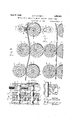
- Fig. et is an enlarged detail vertical cross section of the side trimming rolls and taken approximately on the line 1 -4 of Figure 1 and looking in the direction of the arrows.'
- Fig. 5 is a view similar to Fig. 4 and taken on the line 5--5 of Fig. 1' and showing the construction of the combined beveling and 5! bilge rolls.
- Fig. 6 is a detail transverse section showing the trimming and bilge rolls together with the cut-oit knife and croze die when the parts are positioned for bilging and crozing a barrel stave.
- Fig. 7 is a view similar to Fig. 6 and showing the positions of the same parts after the bilge and croze have been formed in a stave.
- . 8 is a detail of vertical cross section 65 cut-oil knife taken on the line'8-8 of Fig. 6.
- Fig. 9 is a fragmentary plan view ofthe blank of this invention showing one end portion thereof partly formed into a barrel stave and further showing an end portion of a finished barrel. stave removed from the blank.
- Fig. 10 is a view similar to Fig. 9 but showing the modified end portions ofl the blank shaped so as to provide tub staves.
- Fig. 11 is a vertical cross section of the n rolls, dies and cutters for forming the tub -staves of Fig. 10. other objects are accome n
- A indicates asuitable upright 'frame adapted in any pre- 80 fer-red manner for supporting the various elenients hereinafter described.
- the contour of frame A is preferably right angular 'in plan view.
- This construction although not" absolutely essential, requires acrelatives 35 l ly, ⁇ short length' of. floor space to ⁇ laccommodate the machine.
- Suitable bearings 5-5 are providedin. ⁇ the side portions Gof the frame for the'end ortions vof a horizontally disposed shaft?
- the layers 9A are arranged in a common horizontal plane upon moving away from knives 19 and until they approach the angularly disposed opposite side portion 16 of'frame A at which time a change is made in the direction of progressive movement of the layers and also in their relative positions.
- These changes are edected by a deflector in the form of an inclined series of rolls 15, disposed with theiraxes oblique to the long axis of the side portion 16, of frame A.
- the layers are directed under and around the rolls 15 which, by reason of their arrangement in an inclined plane, operate to ⁇ position the various layers, one above the other .and direct the same between the side members ⁇ 17, of side portion 16, of the frame.
- Each of the trays 20, is adapted for containinga quantity of adhesive substance 24, and a. roll 25, is disposed so -as to be immersed in the adhesive 24, so that when one of the layers 9, is directed downwardly and under the said roll each tray and are provided fo'r guiding certain of the layers into and out of the trays and forl guiding others of the layers across and out of contact with the trays, and further for permittingvthe convergence of the layers in moving away from the frame 21.
- the layers 9, at their points of convergence pass between al pair of horizontally disposed upper and lower rolls 28 and 29, which operate to combine initially the dry layers with those carrying coatings of adhesive.
- a bracket-arm 30, or its equivalent is provided for supporting the combining rolls 28 and 29.
- the combined layers, upon moving away from the combfning rolls 28 and 29, are formed in to the laminated blank indicated by 3 0', in Figs. 1 and 2.
- the blank 30, may subsequently be operated upon to assume a variety of forms, depending upon its size-and the ultimate use to be made thereof.
- the die or shaping. mechanism for operating upon blank 30 is indicated generally by B and is located within the .side portion 16, of frame A, extending throughout the 4side portion from a point adjacent to the combining rolls 28 and 29. 'In the present case and for purposes of illustration, I have shown the die mechanism B as being adapted in operating upon blank 30 to form the same into staves suitable for making barrels, tubs and the like.
- each of the layers 9 which go to make up blank 30 is of a width corresponding to the width of the stave to be formed.
- the extreme end of mechanism B, adjacent to rolls 28 and 29, consists of a lower roll 31, having a concaved periphery 32, conforming to convexl periphery 33, of an upper roll 34, arranged in alignment with roll 31.
- Horizontally disposed shafts 35 and 36 pass through the central portions of rolls 31 and 34, and operate to rotate the rolls by being keyed thereto, as
- Circular flanges 38 and 39 are provided for preventing lateral displacement of tical guides 43, formed in oppositely disposed uprights, one of which is shown in Figs.
- the compression springs are interposed ⁇ between boxes 39 and 40, on either end portions of shafts 35 and 36.
- the lower cross heads bear upon the lower ends of the guides and the adjusting screws, one of which is shown in Figs. 2 and 3 and indicated by 46, are screwed through the heads 'at the upper ends of uprights 44, so as to be turned into contact with the upper boxing 39, all of which is .shown in Figs. 2 and 3.
- the springs 45 operate normally to yieldingly hold the upper roll 34, in spaced relation to the lowei ⁇ roll 31, so that by turning the screws 46, the space between said rolls may be diminished transversely and in accordance with the thickness of blank 30 to obtain the required degree of pressure upon the said blank. In that there may hinder tendency on the part of the rolls 31 and 33 to set up a differential in the ratev of movement of the adjacent or remote portions ofthe blank in contact with said rolls.
- Figs. 1 and 2 it is to be noted that additional upper-and lower rolls, identical in construction with rolls 31 and 34, are provided to further carry out the operation of imparting the transverse curvature to the blank which is, as shown, directed betweenlthe various sets of upper and lower rolls. 1The i number of these sets to be em loyed may vary with the type f blank to e operated upon, and this holds true, regardless 'as to lwhether the blank is to be shaped, as just described, or otherwise. In Fig. 1 it is to v'be noted that the rolls 31 and 34, which initial.
- the condition of the blank is such as to permit of the trimming and finishing thereof immediately after moving away from one or more pairs of the rolls 31 and 34, and in other instances it may be found necessary to delay slightly the trimming and finishing operations. Where such delay necessary it is proposed to prevent change in the transverse curvature of the blank by directing the blank between a series 51, of upper convex rolls and lower concave rolls, located in the side portion ⁇ 16, and outwardly beyond the series of pressure rolls.
- the convex upper rolls bear u on the lower concave rolls and are distinguished from the pressure rolls in that they are mounted as idlers in the frame nd each ofthese rolls is formed of one piece as distinguished from the sectional construction of the pressure rolls 31 and 34.
- vthis finishing mechanism includes first, a blank trimming and beveling die; second, a bilge-forming die; and third, a stave-cutting andcrozing die,--sov that the continuous blank as it approaches or enters air of oppositely sloped circularcuttingA lades 56 and 57 operating upon or in conjunction with oppositely sloping flanges 58 and 59.
- the circular ⁇ blades 56 and 57 are disposed upon the ends of an upper roll 60 having a convex barrel 61 and the rings or flanges 58 and 59 are disposed at the ends of a lower roll 62 having sloped end surfaces 63 and a concave barrel 64.
- the roll 60 is keyed to a shaft 65 and horizontally supported thereon by the said portion 16 of the frame a.
- the roll 62 is keyed to a shaft 66 and is supported horizontally thereby in .vertical alignment with the roll 60.
- Therolls 60 and 62 operate to support and convey the blank 30 as the same is beveled and trimmed by the cutting edges of the blades 56 and 57.
- Any sui-table means such as screws 67, may beemployed for securing the blades tothe roll 60.
- the rolls 60 and 62 operate at corresponding speeds and are so disposed with respect to the pressure rolls and to each other that the blank upon moving away from the pressure rolls enters directly between rolls 60 and 62 and moves for a distance equal to the length of the stave, shown in Fig. 9, in each revolution of the rolls 60 and 62.
- the blank with the longitudinal redges thereof trimmed as shown in Figs. 9
- the upper roll 69 like the roll 60 previously mentioned, has a convex surface which works in a corresponding concave surface or barrel of thevroll 71.
- the rolls 69 and 71 are keyed to shafts eccentrically disposed therein and respectively indicated by 74 and 75. These shafts are mounted in suitable bearings in the side portion 16 of frame A.
- the segment of the roll 69, farthest removed from the axis of the shaft 74, is disposed opposite to segment of l the roll 71, nearest to the shaft 75.
- the said axis of the shaft 71 is also spaced from the axis of shaft 4741 for a distance corresponding approximately to one-half the length of the stave 77.
- the en d portion of the stave 77 after moving away from the rolls 69 and 71, is directed over a fianged ⁇ roll ⁇ 82, keyed to a shaft 83, which is transversely disposed in the side portion 16, i
- the blade 84.- of the die 78, and I n the transverse ribs 85, disposed to either side of theblade 84, are turned into contact with the stave 77, as shown in Fig. 6, the knife operating to sever the blank forming the stave 77 and the ribs 85, operating to impress the adjacent ends of the severed sportions and thereby form a croze in each.
- the outer end ofthe die 7 disposedv between the ribs 85 and knifeY 84, is bevelled, as at 86; these bevelled portions operating to bevel the adjacent ends of" the severed portions so as to form the usual chimes.
- ⁇ Fig.,7 showsthe position occupied by the various rolls after one stave has been formed and before the same has been severed.
- y Fig. 9 shows a fragment of a finished stave and the adjacent end ofthe continuous blank with the free end thereof provided with a cro'ze and chime.
- the rolls 87 and. 88 are concentrically disposed upon their shafts 89 and 90.
- These ⁇ rolls are ⁇ constructed for and operate to trim and bevel the sides of the blank, as described in connection with the rolls 60 'and 62 but said rolls, on account of their concentric arrangement with shafts 89 and 90, do not operate to impart a bilge and curve tothe blank, asu
- a. pair of oppositely disposed combined cut-ofi' and croze dies respectively indicated by 91 and 92.
- These dies are disposed in diametrically opposite portions of a roll93, keyed to a transversely disposed shaft in the side portion 16, of the frame A, the said roll being disposed so as to permit the blank, after movof the blank and the adjacent end of a fin-v ished stave 99, as the same is severed from the blank.
- the die 92 is provided with a. blade 100, located between the plane surfaces 101, on the outer end of the die 92.
- the pro- ,vision of these constructions in the dies 91 and 92 provides for the different end constructions found in tub staves; the die 91 operating to form a bottom receiving recess in the lower end of the stave in spaced relation to the lower edge while the die 92 operates to form the usual rabbet in the upper end portion of the stave.
- ⁇ The construction shown in Fig. 11 operates by first forming the bottom receiving recesses 102 and then severing the blank so as toprovide the adjacent ends 103 and 104 and subsequently forming the top or cover receiving rabbets 105 and simultaneously severing the end portion 104 from the portion 106.
- Any suitable form of drive mechanism such as a train of gears'107, may be employed for operating the trimming, bevelling and blank cutting dies, as shown in Fig. 1.
- This construction may be connected with the train indicated by 50, of the same figure, the power being transmitted through sprocket wheels 108 and chains 109, connected to the train 50, as shown.
- a lrotary moistening device of ordinary construction and indicated generally by 110, the roller in the device operating to apply a fluid to the adjacent surface of the blank as the same" moves away from the pressure rolls.
- the lo cation of the moistening device may be sucl as is found desirable. In the present in stance, the same is shown as located between the first series of pressure rolls on the left of Fig. 1, and adjacent to theseries of idlers 51.
- What I claim is: 1. .
- the method of making a laminated blank of fibrous material which consists in continuously unwinding a rolled sheet of fibrous material, continuously cutting the sheet to provide a plurality of layers of corresponding widths, continuously arranging the layers with their flat faces in opposed relation, continuously applying a coating of adhesive to adjacent faces of the layers simultaneously, continuously superimposing the coated surfaces one upon the other and thereby forming a blankand finally continuously trimmingr the longitudinal edges ofthe blank by feeding the same between the elements of a rotary cutting mechanism.
- va machine for making laminated fibrous blanks from a single sheet of fibrous material, a supportfor the fibrous sheet, a rovtary cutting device adapted for continuous-l ly cutting the sheet into a plurality of layers of corresponding width, means for applying a coating of adhesive to adjacent faces of cent faces of the layers simultaneously andthe layers simultaneously, and means for continuously moving the layers from the cutting device and into contact with the adhesive applying means, and means for continuously arranging the layers with their coated faces between they successive layers, together with means for continuously superimposing the one upon the other and pressing the layers to provide a blank.
- a support for the fibrous sheet a rotary cutting device adapted for continuously cutting the sheet into a-plurality of layersv of corresponding width, means for applying a coating of adhesive to adjacent faces of the layers simultaneously, and means for continuously moving the layers from the cutting device and into contact with the adhesive applying means, means for continuously arranging the layers with their coated faces between the successive layers, together with means for continuously superimposing the layers one upon the other and pressing the layers to provide a blank, and means for continuously trimming and beveling the longitudinal side edges of the blank.
- rotary means for cutting a sheet into a plurality of layers and for applying adhesive to adjasuperimposing the layers one upon the other to provide a blank, pressure rolls adapted for continuously pressing the blank and adapted to impart a transverse curvature thereto, a
- thebla longitudinally as the same is xioved by the pressure rolls away from the cutting device, and mea-ns for intermittently cutting curved sections of predetermined length from the blank.
- ro-O tary means for cutting a sheet into a plurality of layers and for applying adhesive to adjacent faces of the layers simultaneously and superimposing the layers one upon the other to provide a blank, pressure rolls adapted for continuously pressing the blank and adapted cutting device for trimming the longitudinal edges of the blank as the same moves away from the pressure rolls, means for curving the blank longitudinally as the same is nioved by the pressure rolls away from the cutting device, and means for intermittently cutting curved'sections of predetermined length from the blank and impressing the said sections -with transverse recesses.
- u 'means for cutting a sheet into a plurality of layers and for applying adhesive to the' layers' and superimposing the layers one upon the other ltop provide a blank, pressure rolls adapted for continuously pressingthe blank and imparting a transverse curvature thereto, a cutting device for trimming the longitudinaledges of the blank, and means for intermittently cutting sections of predetermined length from the blank.
- means for cutting a. sheet into a plurality of layers and for applying adhesive to the layers and superimposing the layers one upon the other to provide a blank a cutting device for trimming the longitudinal edges of the blank, means for curving the blank longitudinally as the same is moved away from the cutting device, and means for intermittentl ⁇ cutting sections of predetermined lengt layers and for applying adhesive to the lay-y ers and superimposing the layers -one upon the other to provide a blank, pressure rolls adapted for continuously pressing the blank, a cutting device fortrimming the longitudinal edges of the blank, and means for intermittently cutting section-s of predetermined length from the blank and for impressing the said sections with a transverse recess.
- the method of making a laminated barrel stave out of fibrous material which" inludes continuously arranging layers of the hrous material with their flat faces in opposed relation, continuously applying a coating of adhesive to adjacent faces of the layers simultaneously, continuously superimposing the layers and thereby forming a blank, and continuously trimming the longitudinal edges of the blank by feeding the same between theelements of a rotary cutting mechanism.
- the method of making a laminated barrel stave out of fibrous material which includes continuously arranging the layers with their flat faces in opposed relation, continuously applying a coating of adhesive to adjacent faces of the layers simultaneously, continuously superimposing the layers and therebyforming a blank, continuously trimming and beveling the longitudinal side edges of the blank by feeding the same between the tudinal side edges of the blank.
- a machine for making laminated barrel 'staves out of fibrous material means for applying adhesive to a plurality of layers of fibrous material, means or superimposing the layers to form a barrel stave blank, pressure rolls for continuously pressing the blank 5 and impartinor a transverse curvature thereto, a cutting ,device Jfor trimming the longitudinal edges of the blank, and means for intermittently cutting sections of predetermined length from the blank.
- a machine for making laminated barrel staves out of fibrous material means for applying adhesive to a lurality of layers of fibrous material, means or superimposing the layers one upon the other to provide a 35 barrel stave blank, a cutting device for trimming the longitudinal edges of the blank, means for curving the blank longitudinally as the same is moved away from the cutting device, and means for intermittently cutting 29 sections of ⁇ predetermined length from the blank.
- a machine for making laminated barrel staves out of fibrous material means for applying adhesive to a plurality of layers 25 of fibrous material, means for superimposing the layers to form a barrel stave blank, pressure rolls for continuously pressing the blank and for imparting a transverse curvature thereto, a cutting device lfor trimming the 30 longitudinal edges of the blank, means for curving the blank longitudinally as the same is moved away from the cutting device, and means for intermittently cutting sections of predetermined length from the blank.
- 35 17 In a machine for making laminated barrel staves out of fibrous material, means for applying adhesive to a plurality of layers v of fibrous material and for superimposing the layers to form a barrel stave blank, pressure o rolls fon continuously pressing the blank, a cutting device for trimming the longitudinal edges of the blank, and means for intermittently cutting sections of predetermined length from the blank and for impressing the *5 said sections with a transverse. recess.
Landscapes
- Making Paper Articles (AREA)
Description
April 5, 1932. E. P. EVERETT- ,1,852,451
METHOD AND APPARATUS FOR MAKING LAMINATED FIBROUS BLANKS Filed Sept. l5, 1926 3 Sheets-Sheet 1 forming apparatus.
Patented Apr. 5, 1932 UNITED sTATEsrATENr OFFICE ERNEST P. EVERTT, OF YONKERS, NEW 'YORK METHOD AND AFPARATUS FOR MAKING LAMINATED FIBROS BLANES Application led September 15, 1926. Serial No. 135,511.
the layers thereof and continuously apply ing pressure by feeding the blank as produced between pressure rolls and linally cutting pressed sections of 'predetermined lengths from the blank simultaneously with the movement thereof between the rolls. In connection with the present invention :it-is further proposed to provide a novel die construction for shaping and trimming the blank, and which die or dies is or areadapted` to operate continuously upon the laminated blank as the same is formed.
ln view of the foregoing, the general object of the present invention 1s to provide for the making of finished laminated blanks of fibrous material in a cheap, eEect-ive and eX- peditious manner.
The above and plished by instr'umentalities and steps pointed out in the following specification.
The invention is clearly defined in the claims.` f- Y v A satisfactory embodiment. of. the appara tus .ias constructed for making 'a laminated blank isillustrated in thea accompanying drawings forming part of the specification and inwhich:
- Fig.' 1 isa contracted' plan viewofo'nelem bodiment'of machine used in connection with the present invention. f Fig. 2 is an enlarged side elevation, partly in section showing the delecting rolls for the layers of yfibrous material togetherwth the adhesive coating apparatus and the blank Fig. 3 is an enlarged detail cross section approximately on the line 3-3 of Fig..2 looking in the direction of the arrows.
Fig. et is an enlarged detail vertical cross section of the side trimming rolls and taken approximately on the line 1 -4 of Figure 1 and looking in the direction of the arrows.'
Fig. 5 is a view similar to Fig. 4 and taken on the line 5--5 of Fig. 1' and showing the construction of the combined beveling and 5! bilge rolls.
Fig. 6 is a detail transverse section showing the trimming and bilge rolls together with the cut-oit knife and croze die when the parts are positioned for bilging and crozing a barrel stave.
Fig. 7 is a view similar to Fig. 6 and showing the positions of the same parts after the bilge and croze have been formed in a stave.
. 8 is a detail of vertical cross section 65 cut-oil knife taken on the line'8-8 of Fig. 6. Fig. 9 is a fragmentary plan view ofthe blank of this invention showing one end portion thereof partly formed into a barrel stave and further showing an end portion of a finished barrel. stave removed from the blank.
Fig. 10 is a view similar to Fig. 9 but showing the modified end portions ofl the blank shaped so as to provide tub staves.
Fig. 11 is a vertical cross section of the n rolls, dies and cutters for forming the tub -staves of Fig. 10. other objects are accome n In the embodiment of the present invention as shown in the drawings, A indicates asuitable upright 'frame adapted in any pre- 80 fer-red manner for supporting the various elenients hereinafter described. The contour of frame A is preferably right angular 'in plan view. A* This construction, although not" absolutely essential, requires acrelatives 35 l ly,` short length' of. floor space to `laccommodate the machine. Suitable bearings 5-5 are providedin.`the side portions Gof the frame for the'end ortions vof a horizontally disposed shaft? of) fibrous material 8 which is insertable through the open end of side portion 6 and between the side members thereof. The sheet which makes up the roll 8 is cut into a plurality of symmetri fallayers 9 by a` series of spaced circular cutters orknives 10, secured to a power driven shaft 11 which is mounted in bearings 12 in the side members of side portion 6 inwardly and beyondthe axis of `-roll v8. Each of the layers 9 corresponds apa. lroll of paper or other 'a similarly disposed lower roller 14 are disposed for supporting thebrous sheet of roll 8, in operative relation to knives 10, suitable bearings such as 15 being provided for roller 13 and similar bearings (not shown) are provided for roller 14. The layers 9A are arranged in a common horizontal plane upon moving away from knives 19 and until they approach the angularly disposed opposite side portion 16 of'frame A at which time a change is made in the direction of progressive movement of the layers and also in their relative positions. These changes are edected by a deflector in the form of an inclined series of rolls 15, disposed with theiraxes oblique to the long axis of the side portion 16, of frame A. The layers are directed under and around the rolls 15 which, by reason of their arrangement in an inclined plane, operate to` position the various layers, one above the other .and direct the same between the side members` 17, of side portion 16, of the frame. I
As shown in Fig. 2 the end portions 18, of the rolls 'are journalled in bearings 19, secured to the stepped sideplates 20. For purposes of illustration, there is shown an arrangement forforming a laminated blank from 7 layers of brous material.
In this connection it is proposed to apply adhesive to the opposite faces of alternately disposed layers arranged between the uppermost and the lower-most layers with theresult that when the layers are-pressed together in superimposed relationship adhesive will coat adjacentfaces of the layers but leave the outside faces, that is the top and bottom` of the-blank, uncoated. This proposal involves the use of a plurality of horizontally disposed trays 20, arranged in spaced relation,`one above the other and suitably secured to upright 21, and arranged within the side portion 16 of the frame adjacent to the delecting rollers 15. A plurality of guide rollers 22, are arranged oneabove the other in a frame 23 and disposed between the rolls 15, and the trays 20. The various layers 9,
upon moving away from the rolls 15, are
positioned in operative relation to their respective trays 20. Each of the trays 20, is adapted for containinga quantity of adhesive substance 24, and a. roll 25, is disposed so -as to be immersed in the adhesive 24, so that when one of the layers 9, is directed downwardly and under the said roll each tray and are provided fo'r guiding certain of the layers into and out of the trays and forl guiding others of the layers across and out of contact with the trays, and further for permittingvthe convergence of the layers in moving away from the frame 21. The layers 9, at their points of convergence pass between al pair of horizontally disposed upper and lower rolls 28 and 29, which operate to combine initially the dry layers with those carrying coatings of adhesive.
A bracket-arm 30, or its equivalent is provided for supporting the combining rolls 28 and 29. The combined layers, upon moving away from the combfning rolls 28 and 29, are formed in to the laminated blank indicated by 3 0', in Figs. 1 and 2. The blank 30, may subsequently be operated upon to assume a variety of forms, depending upon its size-and the ultimate use to be made thereof. The die or shaping. mechanism for operating upon blank 30 is indicated generally by B and is located within the .side portion 16, of frame A, extending throughout the 4side portion from a point adjacent to the combining rolls 28 and 29. 'In the present case and for purposes of illustration, I have shown the die mechanism B as being adapted in operating upon blank 30 to form the same into staves suitable for making barrels, tubs and the like. In this connection it is to be noted that each of the layers 9 which go to make up blank 30 is of a width corresponding to the width of the stave to be formed. The extreme end of mechanism B, adjacent to rolls 28 and 29, consists of a lower roll 31, having a concaved periphery 32, conforming to convexl periphery 33, of an upper roll 34, arranged in alignment with roll 31. Horizontally disposed shafts 35 and 36, pass through the central portions of rolls 31 and 34, and operate to rotate the rolls by being keyed thereto, as
indicated by 37. The transverse dimensions of the surfaces 32 and 33, conform to the width of blank 30 and these surfaces combine to impart the conventional concavo-con- Vex cross sectional contour to the blank 30 as the .same passes between rolls 31 and 34, in
moving away from the combining rolls 28 and 29. Circular flanges 38 and 39, are provided for preventing lateral displacement of tical guides 43, formed in oppositely disposed uprights, one of which is shown in Figs.
2 and 3 and indicated by 44. The compression springs, one of which is shown in Figs. 2 and 3 and indicated by 45, are interposed` between boxes 39 and 40, on either end portions of shafts 35 and 36. The lower cross heads bear upon the lower ends of the guides and the adjusting screws, one of which is shown in Figs. 2 and 3 and indicated by 46, are screwed through the heads 'at the upper ends of uprights 44, so as to be turned into contact with the upper boxing 39, all of which is .shown in Figs. 2 and 3. The springs 45, operate normally to yieldingly hold the upper roll 34, in spaced relation to the lowei` roll 31, so that by turning the screws 46, the space between said rolls may be diminished transversely and in accordance with the thickness of blank 30 to obtain the required degree of pressure upon the said blank. In that there may exista tendency on the part of the rolls 31 and 33 to set up a differential in the ratev of movement of the adjacent or remote portions ofthe blank in contact with said rolls.
and this because of the pressure exerted by the rolls upon the blank and the presence of the curved surfaces of the rolls, it is proposed to overcome such tendency, when found to exist, by constructing the rolls 31 and 34 in sections, as shown in Figs. land 3. In this connection it is to be noted that the end sect'ons 47, of the rolls 31 and 34, are loose upon the respective shafts 35 and 36, and the intermediate sections 48, are keyed to the .said shafts. This construction readily provides a means to compensate for any tendency to irregular movement in the different portions of the blank.
In Figs. 1 and 2 it is to be noted that additional upper-and lower rolls, identical in construction with rolls 31 and 34, are provided to further carry out the operation of imparting the transverse curvature to the blank which is, as shown, directed betweenlthe various sets of upper and lower rolls. 1The i number of these sets to be em loyed may vary with the type f blank to e operated upon, and this holds true, regardless 'as to lwhether the blank is to be shaped, as just described, or otherwise. In Fig. 1 it is to v'be noted that the rolls 31 and 34, which initial.
l'y operate'upon the blank, are `power driven from a pulley 49, secured to shaft 36. Where a plurality of rolls are employed, as shown in Fig. 1, the same are connected by a gear train such as shown, or its equivalent, constructed so as to operate the rolls at corresponding speeds. Provision is made for having the additional rolls, where employed, exert pressure upon the blank in an amount corresponding to or different from the pressure initially exerted by rolls 31 and 34. The devices employed for roducing the required pressure on'the additional rolls are identical with those described in connection with screw 46, for rolls 31 and 34, all of which is shown in Fig. 2. y
In some instances it may be foundthat the condition of the blank is such as to permit of the trimming and finishing thereof immediately after moving away from one or more pairs of the rolls 31 and 34, and in other instances it may be found necessary to delay slightly the trimming and finishing operations. Where such delay necessary it is proposed to prevent change in the transverse curvature of the blank by directing the blank between a series 51, of upper convex rolls and lower concave rolls, located in the side portion `16, and outwardly beyond the series of pressure rolls. In Fig. 1, the convex upper rolls bear u on the lower concave rolls and are distinguished from the pressure rolls in that they are mounted as idlers in the frame nd each ofthese rolls is formed of one piece as distinguished from the sectional construction of the pressure rolls 31 and 34. In some instances it may be lfound desirable to interpose a pair of pressure rolls, as indicated by 52 at a convenient location between adjacent pairs of rolls in the series of rolls 51. It may further be found desirable to apply additional pressure by means ofpressure rolls 54 and 55, to the blank as same moves away from lthe series of rollsy 51. In all instances, the employment of additional pressure rolls will, of course, depend largely, if not wholly, upon the type and size of blank to be operated u on.
When the blank moves away from the pressure rolls or series 51, or the supplemental pressure rolls 54 and 55, as the case may be, the said blank is directed between the dies of the finishing mechanism C. In the present instance vthis finishing mechanism includes first, a blank trimming and beveling die; second, a bilge-forming die; and third, a stave-cutting andcrozing die,--sov that the continuous blank as it approaches or enters air of oppositely sloped circularcuttingA lades 56 and 57 operating upon or in conjunction with oppositely sloping flanges 58 and 59. :The circular` blades 56 and 57 are disposed upon the ends of an upper roll 60 having a convex barrel 61 and the rings or flanges 58 and 59 are disposed at the ends of a lower roll 62 having sloped end surfaces 63 and a concave barrel 64. The roll 60 is keyed to a shaft 65 and horizontally supported thereon by the said portion 16 of the frame a. The roll 62 is keyed to a shaft 66 and is supported horizontally thereby in .vertical alignment with the roll 60. Therolls 60 and 62 operate to support and convey the blank 30 as the same is beveled and trimmed by the cutting edges of the blades 56 and 57. It will be noted thatl the cutting edges of the blades 56 and 57 project beyond the periphery of the roll 60 andv contact or work against the flanges 58 and 59. Therefore suliicientspace is left between the roll 60 and the Corresponding concave section of the roll 62 to permit the passage of the blank therebetween andA at the same time to allow the free and un` restricted trimming and beveling of the edge.
As the blankBO passes between the trimming and beveling dies it will be cut, as indicated in general by Fig. 9-so far as the side edges of the blank are concerned.
Any sui-table means, such as screws 67, may beemployed for securing the blades tothe roll 60. The rolls 60 and 62 operate at corresponding speeds and are so disposed with respect to the pressure rolls and to each other that the blank upon moving away from the pressure rolls enters directly between rolls 60 and 62 and moves for a distance equal to the length of the stave, shown in Fig. 9, in each revolution of the rolls 60 and 62. Immediately after moving away from the rolls 60 and 62 the blank with the longitudinal redges thereof trimmed, as shown in Figs. 9
and l10, and also beveled, enters between a pair ofoppositely sloped bilge rolls 69-71 which are intended to bow or curve Y or bilge the trimmed and beveled stave blank, The upper roll 69, like the roll 60 previously mentioned, has a convex surface which works in a corresponding concave surface or barrel of thevroll 71. :The rolls 69 and 71 are keyed to shafts eccentrically disposed therein and respectively indicated by 74 and 75. These shafts are mounted in suitable bearings in the side portion 16 of frame A. The segment of the roll 69, farthest removed from the axis of the shaft 74, is disposed opposite to segment of l the roll 71, nearest to the shaft 75. With this length of the stave 77. The said axis of the shaft 71, is also spaced from the axis of shaft 4741 for a distance corresponding approximately to one-half the length of the stave 77. The en d portion of the stave 77, after moving away from the rolls 69 and 71, is directed over a fianged`roll`82, keyed to a shaft 83, which is transversely disposed in the side portion 16, i
of frame A` and in vertical alignment with the shaft l81. In the turningmovement of the arm 79, the blade 84.- of the die 78, and I n the transverse ribs 85, disposed to either side of theblade 84, are turned into contact with the stave 77, as shown in Fig. 6, the knife operating to sever the blank forming the stave 77 and the ribs 85, operating to impress the adjacent ends of the severed sportions and thereby form a croze in each. In this connection it is to be noted that the outer end ofthe die 7 8, disposedv between the ribs 85 and knifeY 84, is bevelled, as at 86; these bevelled portions operating to bevel the adjacent ends of" the severed portions so as to form the usual chimes.
-In connection with the arrangement illustrated in Fig. 6, it is to be noted that the rolls 60, 62. 69, ,71, 82 and arm 79, are of corresponding radii and the shafts of these elements rotate at corresponding speeds. Therefore, in each revolution the'said rolls and arm operates to advance the blank 30', for a distance equal tothe length of the stave 77 and in each revolution of the arm 79, one finished stave is severed from the blank and an end portion of the adjacent stave formed with the conventional chime and croze.
`Fig.,7 showsthe position occupied by the various rolls after one stave has been formed and before the same has been severed. y Fig. 9 shows a fragment of a finished stave and the adjacent end ofthe continuous blank with the free end thereof provided with a cro'ze and chime.
Referring to the Fig. that the rolls 87 and. 88, are concentrically disposed upon their shafts 89 and 90. These `rolls are` constructed for and operate to trim and bevel the sides of the blank, as described in connection with the rolls 60 'and 62 but said rolls, on account of their concentric arrangement with shafts 89 and 90, do not operate to impart a bilge and curve tothe blank, asu
described in connection with the rolls 69 and 71. This construction is desirable in the making of tub staves, such-as shown in Fig. 10.
For purposes of illustration, I have shown a construction for making tub staves of sub-v stantially one-half .the length Aof the stave 7 7, of Figs. 6 and 7.
l11, itis tno be noted 'I In this connection there is provided a. pair of oppositely disposed combined cut-ofi' and croze dies, respectively indicated by 91 and 92. These dies are disposed in diametrically opposite portions of a roll93, keyed to a transversely disposed shaft in the side portion 16, of the frame A, the said roll being disposed so as to permit the blank, after movof the blank and the adjacent end of a fin-v ished stave 99, as the same is severed from the blank. The die 92 is provided with a. blade 100, located between the plane surfaces 101, on the outer end of the die 92. The pro- ,vision of these constructions in the dies 91 and 92, provides for the different end constructions found in tub staves; the die 91 operating to form a bottom receiving recess in the lower end of the stave in spaced relation to the lower edge while the die 92 operates to form the usual rabbet in the upper end portion of the stave.
`The construction shown in Fig. 11 oper ates by first forming the bottom receiving recesses 102 and then severing the blank so as toprovide the adjacent ends 103 and 104 and subsequently forming the top or cover receiving rabbets 105 and simultaneously severing the end portion 104 from the portion 106.
Although I have shown a construction and arrangement for trimmingr and shaping blank 30, so as to provide staves of different construction, it is to be understood that I am not to be limited to the specific construction and arrangement shown.
In some instances it may be found desirable to provide separate dies in sep-araterolls for crozing and cutting the blank.
Any suitable form of drive mechanism, such as a train of gears'107, may be employed for operating the trimming, bevelling and blank cutting dies, as shown in Fig. 1. This construction may be connected with the train indicated by 50, of the same figure, the power being transmitted through sprocket wheels 108 and chains 109, connected to the train 50, as shown.
In some instances it may be desirable tosoften the inner face of the blank so that the Croze and cutting of the blank may be made without distorting the fibrous material'. For this purpose it is proposed to provide a lrotary moistening device of ordinary construction and indicated generally by 110, the roller in the device operating to apply a fluid to the adjacent surface of the blank as the same" moves away from the pressure rolls. The lo cation of the moistening device may be sucl as is found desirable. In the present in stance, the same is shown as located between the first series of pressure rolls on the left of Fig. 1, and adjacent to theseries of idlers 51.
rom the foregoing it is obvious that the embodiment illustrated'is susceptible of various changes 'and I reserve the right to employ such changes as maycome within the scope of the appended claims.
What I claim is: 1. .The method of making a laminated blank of fibrous material which consists in continuously unwinding a rolled sheet of fibrous material, continuously cutting the sheet to provide a plurality of layers of corresponding widths, continuously arranging the layers with their flat faces in opposed relation, continuously applying a coating of adhesive to adjacent faces of the layers simultaneously, continuously superimposing the coated surfaces one upon the other and thereby forming a blankand finally continuously trimmingr the longitudinal edges ofthe blank by feeding the same between the elements of a rotary cutting mechanism.
2. The method of making a laminated blank of fibrous material which consists in continuously unwinding a rolled sheet. of fibrous material, continuously cutting the sheet to provide a plurality of layers of corresponding widths, continuously arranging the layers with their flat faces in opposed relation, continuously applying a coating of adhesive to adjacent faces of the layers simultaneously, continuously superimposing thecoated surfaces one upon the other and thereby forming a blank, continuously trimming and beveling the longitudinal side edges of the blank by feeding the same between the elements of a cutting mechanism, and finally cutting a section of predetermined length from an end Lportion of the blank simultaneously with the/movement of the blank between the elements of the cutc for continuously moving thelayers from the cuttingY device and into contact with the adhesive applying means, and means for continuously arranging the layers with their coated faces between the successive layers.
4. In va machine for making laminated fibrous blanks from a single sheet of fibrous material, a supportfor the fibrous sheet, a rovtary cutting device adapted for continuous-l ly cutting the sheet into a plurality of layers of corresponding width, means for applying a coating of adhesive to adjacent faces of cent faces of the layers simultaneously andthe layers simultaneously, and means for continuously moving the layers from the cutting device and into contact with the adhesive applying means, and means for continuously arranging the layers with their coated faces between they successive layers, together with means for continuously superimposing the one upon the other and pressing the layers to provide a blank. Y
5-- In a machine for making laminated fibrous blanks from a single sheet of fibrous material, a support for the fibrous sheet, a rotary cutting device adapted for continuously cutting the sheet into a-plurality of layersv of corresponding width, means for applying a coating of adhesive to adjacent faces of the layers simultaneously, and means for continuously moving the layers from the cutting device and into contact with the adhesive applying means, means for continuously arranging the layers with their coated faces between the successive layers, together with means for continuously superimposing the layers one upon the other and pressing the layers to provide a blank, and means for continuously trimming and beveling the longitudinal side edges of the blank.
6. In a machine lof the class described, rotary means for cutting a sheet into a plurality of layers and for applying adhesive to adjasuperimposing the layers one upon the other to provide a blank, pressure rolls adapted for continuously pressing the blank and adapted to impart a transverse curvature thereto, a
lcutting device for trimming the longitudinal edges offthe blank as the same moves away froml th pressure rolls, means for curvmg `to impart a transverse curvature thereto, al
thebla longitudinally as the same is xioved by the pressure rolls away from the cutting device, and mea-ns for intermittently cutting curved sections of predetermined length from the blank.
7. In a machine of theclass described, ro-O tary means for cutting a sheet into a plurality of layers and for applying adhesive to adjacent faces of the layers simultaneously and superimposing the layers one upon the other to provide a blank, pressure rolls adapted for continuously pressing the blank and adapted cutting device for trimming the longitudinal edges of the blank as the same moves away from the pressure rolls, means for curving the blank longitudinally as the same is nioved by the pressure rolls away from the cutting device, and means for intermittently cutting curved'sections of predetermined length from the blank and impressing the said sections -with transverse recesses.
8. In a machine ofthe class described,
u 'means for cutting a sheet into a plurality of layers and for applying adhesive to the' layers' and superimposing the layers one upon the other ltopprovide a blank, pressure rolls adapted for continuously pressingthe blank and imparting a transverse curvature thereto, a cutting device for trimming the longitudinaledges of the blank, and means for intermittently cutting sections of predetermined length from the blank. f
9. In a machine of the class described, means for cutting a. sheet into a plurality of layers and for applying adhesive to the layers and superimposing the layers one upon the other to provide a blank, a cutting device for trimming the longitudinal edges of the blank, means for curving the blank longitudinally as the same is moved away from the cutting device, and means for intermittentl `cutting sections of predetermined lengt layers and for applying adhesive to the lay-y ers and superimposing the layers -one upon the other to provide a blank, pressure rolls adapted for continuously pressing the blank, a cutting device fortrimming the longitudinal edges of the blank, and means for intermittently cutting section-s of predetermined length from the blank and for impressing the said sections with a transverse recess.
11. The method of making a laminated barrel stave out of fibrous material, which" inludes continuously arranging layers of the hrous material with their flat faces in opposed relation, continuously applying a coating of adhesive to adjacent faces of the layers simultaneously, continuously superimposing the layers and thereby forming a blank, and continuously trimming the longitudinal edges of the blank by feeding the same between theelements of a rotary cutting mechanism. l2. The method of making a laminated barrel stave out of fibrous material," which includes continuously arranging the layers with their flat faces in opposed relation, continuously applying a coating of adhesive to adjacent faces of the layers simultaneously, continuously superimposing the layers and therebyforming a blank, continuously trimming and beveling the longitudinal side edges of the blank by feeding the same between the tudinal side edges of the blank.
14; In a machine for making laminated barrel 'staves out of fibrous material, means for applying adhesive to a plurality of layers of fibrous material, means or superimposing the layers to form a barrel stave blank, pressure rolls for continuously pressing the blank 5 and impartinor a transverse curvature thereto, a cutting ,device Jfor trimming the longitudinal edges of the blank, and means for intermittently cutting sections of predetermined length from the blank.
19 15. In a machine for making laminated barrel staves out of fibrous material, means for applying adhesive to a lurality of layers of fibrous material, means or superimposing the layers one upon the other to provide a 35 barrel stave blank, a cutting device for trimming the longitudinal edges of the blank, means for curving the blank longitudinally as the same is moved away from the cutting device, and means for intermittently cutting 29 sections of` predetermined length from the blank.
16. ln a machine for making laminated barrel staves out of fibrous material, means for applying adhesive to a plurality of layers 25 of fibrous material, means for superimposing the layers to form a barrel stave blank, pressure rolls for continuously pressing the blank and for imparting a transverse curvature thereto, a cutting device lfor trimming the 30 longitudinal edges of the blank, means for curving the blank longitudinally as the same is moved away from the cutting device, and means for intermittently cutting sections of predetermined length from the blank.
35 17. In a machine for making laminated barrel staves out of fibrous material, means for applying adhesive to a plurality of layers v of fibrous material and for superimposing the layers to form a barrel stave blank, pressure o rolls fon continuously pressing the blank, a cutting device for trimming the longitudinal edges of the blank, and means for intermittently cutting sections of predetermined length from the blank and for impressing the *5 said sections with a transverse. recess.
18. Ina machine for making laminated barrel staves out of fibrous material, means for applying adhesive to a plurality of`layers of fibrous material and for superimposing the layers to-form a barrel stave blank, pressure rolls for continuously pressing the blank Vand for imparting a transverse curvature thereto, a cutting device for trimming the longitudinal edges of, the blank,means for 55 curving the blank longitudinally as the same a is moved away from the cutting device, and
means for intermittently cutting curved sections of predetermined length from the blank v and for impressing the said sections with a o transverse recess.Y
Signed at New York city, in the county of New York and State of New York, this 7th day of September A. D. 1926..
u, ERNEST P.
Priority Applications (1)
| Application Number | Priority Date | Filing Date | Title |
|---|---|---|---|
| US135511A US1852451A (en) | 1926-09-15 | 1926-09-15 | Method and apparatus for making laminated fibrous blanks |
Applications Claiming Priority (1)
| Application Number | Priority Date | Filing Date | Title |
|---|---|---|---|
| US135511A US1852451A (en) | 1926-09-15 | 1926-09-15 | Method and apparatus for making laminated fibrous blanks |
Publications (1)
| Publication Number | Publication Date |
|---|---|
| US1852451A true US1852451A (en) | 1932-04-05 |
Family
ID=22468431
Family Applications (1)
| Application Number | Title | Priority Date | Filing Date |
|---|---|---|---|
| US135511A Expired - Lifetime US1852451A (en) | 1926-09-15 | 1926-09-15 | Method and apparatus for making laminated fibrous blanks |
Country Status (1)
| Country | Link |
|---|---|
| US (1) | US1852451A (en) |
Cited By (13)
| Publication number | Priority date | Publication date | Assignee | Title |
|---|---|---|---|---|
| US2475789A (en) * | 1946-06-25 | 1949-07-12 | Bernard P Kunz | Method and machine for making corrugated structures |
| US2486091A (en) * | 1946-10-16 | 1949-10-25 | R E Mackenzie | Continuously forming fibrous material |
| US2586089A (en) * | 1949-09-01 | 1952-02-19 | Read Standard Corp | Dough sheeting roll |
| US2620513A (en) * | 1950-03-08 | 1952-12-09 | Union Asbestos & Rubber Co | Method of and apparatus for forming pipe insulation |
| US2635670A (en) * | 1949-03-08 | 1953-04-21 | Ragner W Winberg | Process and machine for forming belt assemblies |
| US2665735A (en) * | 1947-08-08 | 1954-01-12 | Steffenino Giuseppe | Production of a continuous monolithic hollow member from heat weldable material |
| US2734532A (en) * | 1956-02-14 | Laminated paper yarns and fabrics | ||
| US2757711A (en) * | 1952-05-05 | 1956-08-07 | Congoleum Nairn Inc | Laminated covering and method and apparatus for making same |
| US2941340A (en) * | 1957-04-19 | 1960-06-21 | Dacam Corp | Carton-formiong and closing means and method |
| US2951006A (en) * | 1953-01-16 | 1960-08-30 | Rubenstein David | Reel-unit and method |
| US2967562A (en) * | 1957-03-18 | 1961-01-10 | W L Gray & Company | Device for laminating plastic sheets |
| US3077000A (en) * | 1959-07-06 | 1963-02-12 | Filon Plastics Corp | Method and apparatus for manufacture of transverse contoured reinforced plastic sheet material |
| US4198257A (en) * | 1979-02-08 | 1980-04-15 | Pfaff Lloyd A | Process for making laminated roofing shingles |
-
1926
- 1926-09-15 US US135511A patent/US1852451A/en not_active Expired - Lifetime
Cited By (13)
| Publication number | Priority date | Publication date | Assignee | Title |
|---|---|---|---|---|
| US2734532A (en) * | 1956-02-14 | Laminated paper yarns and fabrics | ||
| US2475789A (en) * | 1946-06-25 | 1949-07-12 | Bernard P Kunz | Method and machine for making corrugated structures |
| US2486091A (en) * | 1946-10-16 | 1949-10-25 | R E Mackenzie | Continuously forming fibrous material |
| US2665735A (en) * | 1947-08-08 | 1954-01-12 | Steffenino Giuseppe | Production of a continuous monolithic hollow member from heat weldable material |
| US2635670A (en) * | 1949-03-08 | 1953-04-21 | Ragner W Winberg | Process and machine for forming belt assemblies |
| US2586089A (en) * | 1949-09-01 | 1952-02-19 | Read Standard Corp | Dough sheeting roll |
| US2620513A (en) * | 1950-03-08 | 1952-12-09 | Union Asbestos & Rubber Co | Method of and apparatus for forming pipe insulation |
| US2757711A (en) * | 1952-05-05 | 1956-08-07 | Congoleum Nairn Inc | Laminated covering and method and apparatus for making same |
| US2951006A (en) * | 1953-01-16 | 1960-08-30 | Rubenstein David | Reel-unit and method |
| US2967562A (en) * | 1957-03-18 | 1961-01-10 | W L Gray & Company | Device for laminating plastic sheets |
| US2941340A (en) * | 1957-04-19 | 1960-06-21 | Dacam Corp | Carton-formiong and closing means and method |
| US3077000A (en) * | 1959-07-06 | 1963-02-12 | Filon Plastics Corp | Method and apparatus for manufacture of transverse contoured reinforced plastic sheet material |
| US4198257A (en) * | 1979-02-08 | 1980-04-15 | Pfaff Lloyd A | Process for making laminated roofing shingles |
Similar Documents
| Publication | Publication Date | Title |
|---|---|---|
| US1852451A (en) | Method and apparatus for making laminated fibrous blanks | |
| US3187612A (en) | Method for simultaneously cutting overlapping boards from a single sheet | |
| US2759523A (en) | Method and machine for making triple wall corrugated paper board | |
| US2395352A (en) | Box making machine | |
| US3838632A (en) | Method and apparatus for making corrugated containers of longitudinally corrugated strips on continuous basis | |
| US1402259A (en) | Method of and mechanism for making covered box shells | |
| US3285145A (en) | Carton setting up machine | |
| US2008974A (en) | Method for making corrugated board | |
| US2024013A (en) | Manufacture of printed corrugated wrappers | |
| US1410622A (en) | Reenforced-box-blank material and method of manufacturing the same | |
| US3096224A (en) | Corrugated paper board product | |
| US1997718A (en) | Folding box and method of making the same | |
| US1628836A (en) | Apparatus for forming and cutting plastic material | |
| US1944282A (en) | Laminated board and method of making the same | |
| US2110782A (en) | Container and method of making same | |
| US2166126A (en) | Method and apparatus for assembling wrapped boxes | |
| US1970029A (en) | Method of and apparatus for forming channeled strips | |
| US1707712A (en) | Slide-box-shell machine | |
| US3345921A (en) | Method of making a box | |
| US1060740A (en) | Hat-packing-ring machine. | |
| US1693023A (en) | Method of making paper boxes | |
| US2505404A (en) | Machine for corrugating cardboard | |
| US1065681A (en) | Tube-machine. | |
| US3788920A (en) | Method of making rolled edge sealed corrugated paperboard | |
| US770159A (en) | Machine for making cartons or folding boxes. |