US1852440A - Firearm - Google Patents
Firearm Download PDFInfo
- Publication number
- US1852440A US1852440A US467469A US46746930A US1852440A US 1852440 A US1852440 A US 1852440A US 467469 A US467469 A US 467469A US 46746930 A US46746930 A US 46746930A US 1852440 A US1852440 A US 1852440A
- Authority
- US
- United States
- Prior art keywords
- stock
- barrel
- receiver
- recesses
- barrel portion
- Prior art date
- Legal status (The legal status is an assumption and is not a legal conclusion. Google has not performed a legal analysis and makes no representation as to the accuracy of the status listed.)
- Expired - Lifetime
Links
Images
Classifications
-
- F—MECHANICAL ENGINEERING; LIGHTING; HEATING; WEAPONS; BLASTING
- F41—WEAPONS
- F41C—SMALLARMS, e.g. PISTOLS, RIFLES; ACCESSORIES THEREFOR
- F41C7/00—Shoulder-fired smallarms, e.g. rifles, carbines, shotguns
- F41C7/02—Pump-action guns, i.e. guns having a reciprocating handgrip beneath the barrel for loading or cocking
-
- F—MECHANICAL ENGINEERING; LIGHTING; HEATING; WEAPONS; BLASTING
- F41—WEAPONS
- F41A—FUNCTIONAL FEATURES OR DETAILS COMMON TO BOTH SMALLARMS AND ORDNANCE, e.g. CANNONS; MOUNTINGS FOR SMALLARMS OR ORDNANCE
- F41A11/00—Assembly or disassembly features; Modular concepts; Articulated or collapsible guns
Definitions
- This invention relates to firearms and has for an object an improved target rifle of the sliding action rod type.
- the receiver comprises a barrel portion and a stock portion which are interconnected in a manner permitting them easily to be separated for taking down the gun.
- the barrel portion is provided with a pair of side plates fitting 1 within the side walls of the stock portion.
- the carrier is pivotally mounted between said plates and the breech bolt assembly is slidably mounted therebetween.
- the trigger and hammer are pivotally mounted on the stock portion of the receiver and one side wall of the stock portion is detachable to uncover the correspondin side plate of the barrel portion and also the trigger and hammer.
- a springpressed plunger is provided in the stock and between it and the hammer there is provided a rod, the ends of which seat in recesses, one in the plunger and the other in the hammer.
- This rod may easily be removed from between the plunger and the hammer without removal of either from the rifle.
- Fig. 1 is a side elevation of a rifle embodying the invention.
- Fig. 2 is a similar view with the barrel portion disconnected from the stock portion.
- Fig. 3 is a section on the line 3-3 of Fig. 1.
- Fig. 4 is a plan view partially broken away of the stock portion.
- Fig. 6 is a fragmentary reverse view of the barrel portion.
- Fig. 7 is a fragmentary viewof the stock portion partially in section and with the detachable side wall removed, and
- Fig. 8 is a section on the line 88 of Fig. 7.
- the rifle comprises a standard stock 10 and a barrel 11 connected by means of a twopart receiver 12.
- the magazine 13 is supported beneath the barrel 11 and communicates with the receiver 12.
- An action rod handie 14 is slidably supported by the magazine 13 and is connected to an action rod 15 which extendsinto the receiver through the front wall thereof.
- a portion 12 of the receiver' is carried by the barrel and is provided with side walls 16.
- a spacing pin 16 is arranged between the side walls 16 and maintains said walls properly spaced.
- the remainingportion 12 of the receiver is carried by the stock 12 "and is provided with an integral side wall 05 17 and a detachable side plate 17 a which overlie the walls 16 and engage the portion 12.
- the portion 12 is provided with recesses 18 within which are received prongs 19 provided on the stock portion 12
- the barrel portion 12 and stock portion 12 are provided near their front ends with co-acting oblique surfaces 20 and 20*, the contacting of which is effective to draw the prongs 19 into the recesses 18.
- the two parts 12 and 12" are assembled by inserting the prongs '19 into the recesses 18 with the barrel portion and stock portion angularly related and then swinging the same to bring the co-acting surfaces 20 and 20 into contact.
- the barrel 8C portion 12" is provided with an oblique slot 21 which receives a bolt 22 carried by'the walls of the stock portion 12 One end of this bolt lies substantially flush with the side wall 17 and is fixed thereto, while theother end projects through a hole in the removable side plate 17*.
- a nut 23 is threaded on the projecting end of the bolt 22 and has a portion 24 of reduced diameter adapted topass through the hole in the side plate 17 and into a countersunk recess at the end ofthe slot 21. This nut, when the portion 24 is engaged in the countersunk recess, effectively prevents relative angular movement of the stock and barrel portions, thereby holding the same in assembled relation.
- the breech bolt 25 is operated in the wellknown manner by the action rod '15'to which it is connected.
- the action rod 15 lies in a slot 26 in a side wall-l6 and is provided with a lug 27 which projects into a slot 28 provided for it in the breech bolt.
- the carrier 29 is pivotally supported between the walls 16 by a pin 80.
- A. hammer 31 is rotatably mounted on a stud 82 supported by a wall of the stock portion 12 and a trigger 33 is pivotally supported by the stock portion and cooperates with the hammer in the usual manner.
- the receiver is provided wita a tang portion which comprises a tubular member 34 provided with a head 35 having a tapering por tion which is received within a corresponding recess formed partly in the rear wall of the stock portion and partly in the removable side plate 17.
- a bolt 36 is provided in the rear Wall of the stock and is threaded into the head 35 and a bolt 36 passes through the side plate and is also threaded into the head 35.
- the tubular member extends rearwardly from the stock portion and in it is provided the hammer actuating spring 37, the front end of which engages aplunger 38 slidably mounted in the tubular member.
- the front end of the plunger 88 is recessed and receives one end of a rod 39, the other end of which is received within a vertical recess 40 in the hammer 31.
- a bushing 41 Near the rear end of the stock 10 there is provided a bushing 41 through.
- wvhich extends a bolt 42 which is threaded into the rear end of the tubular member 34;.
- the stock portion 12 is provided around the tubular member 3a with a recess into which projects the nose of the stock 10.
- the stock 10 is held to the stock portion 12 through the medium of a bolt l2 and tubular member 34.
- the side plates 17 may be removed by taking out the bolt 36 and screwing off the nut 23 which is replaced aft r the plate has been removed.
- the side plate 17 when removed, uncovers the corresponding side wall 16 and also the hammer and trigger which may be removed while the remaining parts are retained in assembled relation.
- the hammer In order to take out the hammer with the side wall removed, the hammer is moved into cocked position, thus forcing the plunger 88 into the tubular member 37. A. suitable tool is then inserted through the hole for the bolt 36 to retain the plunger within the tubular member. The hammer is then returned to firing position whereupon the bar 39 may be easily lifted out after which the hammer may be slid off the stud 32.
- This feature is v ery helpful in connection with making the final adjustments on the hammer and trigger for obtaining the proper pull on the trigger and also for making other changes incidental to the final adjustment of the gun.
- a receiver comprising a barrel portion and a stock portion, recesses at the rear end of said barrel portion, prongs n d stock portion fitting in said recesses, co-acting longitudinally oblique surfaces on the stock and barrel portions at the front end thereof adapted upon Contacting to pull said prongs longitudinally into said recesses, and means for locking said barrel and stock portions against relative angular movement.
- a receiver comprising a.
- barrel portion and a stock port-ion said barrel portion being provided with side walls underlying the side walls of the stock portion, recesses at the rear end of the said barrel portion, prongs on said stock portion fitting in said recesses, co-acting longitudinally oblique surfaces on said stock and barrel portions at the front end thereof adapted upon contacting to pull said prongs longiudinally into said recesses, and means for locking the barrel and stock portions against relative angular movement.
- a receiver comprising a barrel portion and a stock portion, recesses at the rear end of said barrel portion, prongs on said stock porlion fitting in said recesses, co-acting longitudinally oblique surfaces on the stock and barrel portions at the front end thereof adapted upon contacting to pull said prongs longitudinally into said recesses, a bolt carried by the side walls cf the stock portion, an oblique slot in the barrel portion for receivin said bolt, and a nut threaded on said bolt, a portion of said nut being received within a recess in said barrel portion to prevent relative angular movement of said stock and barrel portions.
- a receiver comprising a barrel portion and a stock portion, said barrel portion being provided with side walls underlying the side walls of the stock portion, recesses at the rear end of the said bar-- rel portion, prongs on said stock portion fitting in said recesses, co-acting longitudinally oblique surfaces on said stock and barrel porlions at the front end thereof adapted upon contactin to pull said prongs longitudinally into said recesses, a bolt carried by the side walls of the st ck portion, an oblique slot in the barrel portion for receivsaid bolt, and a nut threaded on said belt, a portion of said bolt being received within a recess in said barrel portion to prevent relative angular movement of said stock and barrel portions.
- a receiver comprising a barrel portion, a stock portion, recesses at the rear end of said barrel portion, prongs at the rear end of said stock portion fitting in said recesses, co-acting longitudinally oblique surfaces on said stock and barrel portions on the front end thereof adapted upon contacting to pull said prongs longitudinally into said recesses, means for locking said barrel and stock portions against relative angular movement, a trigger and a hammer pivoted to said stock portion, a breech bolt slidably mounted in said barrel portion, and a carrier pivotally supported by said barrel portion.
- a receiver comprising a barrel portion, a stock portion, recesses at the rear end of said barrel portion, prongs at the rear end of said stock portion fitting in said recesses, co-acting longitudinally oblique surfaces on said stock and barrel portions on the front end thereof adapted upon contacting to pull said prongs longitudinally into said recesses, means for locking said barrel and stock portions against relative angular movement, a trigger and a hammer pivoted to said stock portion, a breech bolt slidably mounted in said barrel portion, and a carrier pivotally supported by said barrel portion, one of the side walls of the stool: portion being removable to uncover the trigger and hammer.
- a receiver comprising a barrel portion, a stock portion, said barrel portion being provided with walls under lying the side plates of the stock portion, recesses at the rear end of said barrel portion, prongs at the rear end of said stock port-ion fitting in said recesses, co-acting longitudinally oblique surfaces on said stock and barrel portions at the front end thereof adapted on contacting to pull said prongs longitudinally into said recesses, means for locking said barrel and stocli portions against relative angular movement, a ham mer, and a trigger pivotally supported by said stock portion, a breech bolt slidably supported by said barrel portion, and a carrier pivotally supported by said barrel portion.
- a receiver comprising a barrel portion, a stock portion, said barrel portion being provided with walls underlying the side plates of the stock portion, recesses at the rear end of said barrel portion, prongs at the rear end of saic stock portion fitting in said recesses, co-acting longitudinally oblique surfaces on said stock and bar rel portions at the front end thereof adapted on contacting to pull said prongs longitudinally into said recesses, means for locking said barrel and stock portions against relative angular movement, a hammer and a trigger pivotally supported by said stock portion, a breech bolt slidably supported by said barrel portion, and a carrier pivotally supported by said barrel portion, one of the side plates of the stock portion being removable to uncover the corresponding side wall and also the trigger and hammer.
- a receiver comprising a barrel portion, a stock portion, said barrel portion being provided with side walls underlying the side plates of the stock portion, recesses at the rear end of said barrel portion, prongs on said stock portion extending into said recesses, co-acting longitudinally oblique surfaces on the stock-and barrel portions at the front end thereof adapted upon contacting to pull said prongs longitudinally into said recesses, means for locking the barrel and stock portions against relative angular movement, an action slide extending into said receiver, said slide being received in a slot in a side wall of said barrel portion.
- a receiver comprising stock and barrel portions having interengaging projections and recesses at one end, coacting longitudinally oblique surfaces on said stock and barrel portions at the other end adapted upon contacting to draw said projections and recesses longitudinally into engagement, and means for locking said barrel and stock portions against relative angular movement.
- a receiver comprising stock and barrel portions having interenga-ging projections and recesses at one end, co-acting longitudinally oblique surfaces on said stock and parallel portions at the other end adapted upon contacting todraw said projections and recesses longitudinally into engagement, a bolt carried by said stock portion at the other end, an oblique slot in the barrel portion for receiving said bolt, and a nut threaded on said bolt for clamping said portions in assembled relation.
- a receiver comprising a barrel portion and a stock portion, said barrel portion being provided with side walls underlying the side plates of the stock portion and having an open top, a breech bolt slidably supported by said barrel portion, an action slide arranged in a slot in a side wall of said barrel portion and closing the open top thereof and operatively connected to said breech bolt, and a carrier pivotally mounted between said walls.
- a receiver In a. firearm, a receiver, a tapering rectangular recess in the rear of said receiver, a tubular tang having a tapering rectangular head received Within said recess, means to lock said head in said recess, a spring-pressed plunger in said tang, a hammer pivoted in said receiver, and a rod having one end seated in a recess in the end of said plunger and its other end seated in recess in said hammer.
- a receiver having an eX- ternal recess in its rear Wall, a stock having a reduced portion extending into said recess, a tapered rectangular internal recess in the rear wall of said receiver, a tubular tang having a tapered rectangular head fitting in said recess, a bolt carried by said stock and threaded into said tang, a spring pressed plunger in said tang, a hammer pivotally mounted in said receiver, and a bar having one end seated in a recess in said plunger and the other end seated in a recess in said hammer.
- a receiver having an external recess in itsrear wall, a stock having a reduced portion extending into said recess, a tapered rectangular internal recess in the rear wall of said receiver, a tubular tang having a tapered rectangular head fitting in said recess, a bolt carried by said stock and threaded into said tang, a spring pressed plunger in said tang, a hammer pivotally mounted in said receiver, and a bar having one end seated in a recess in said plunger and the other end seated in a recess in said hammer, one side plate of said receiver being removableto uncover the head of said tang and also said hammer, and a bolt passing through said side plate and threaded into said head for detachably connecting said side plate to said receiver.
- a receiver comprising a barrel portion and a stock portion, said barrel portion being provided with side walls and having an open top, a breech bolt slidably supported by said barrel portion and being adapted to close the open top thereof, a carrier pivotally mounted between said walls, and an action slide arranged in a slot in a side wall of said barrel portion and be ing operatively connected to said breech bolt and carrier.
- a receiver comprising a barrel portion and a stock portion, said barrel portion being provided with side walls, and having an open top, a breech bolt slidably supported by said barrel portion and being adapted to close the open top thereof, a carrier pivotally mounted between said walls, an action slide arranged in a slot in a side wall of said barrel portion and being operatively connected to said breech bolt and carrier, and a spacing member arranged between said side walls.
- a receiver comprising a barrel portion having side walls, a stock portion having an integral side wall and an assembled side plate overlying the walls of the barrel portion, a tang portion having a head. seated in a recess formed partly in the rear wall of said stock portion and partly in said assembled side plate, and means for fastening said side plates to said stock portion.
- Patent No. 1,852,440 Granted April 1, 1932, t
- Patent No. 1,852,440 Granted April 1, 1932, to
Landscapes
- Engineering & Computer Science (AREA)
- General Engineering & Computer Science (AREA)
- Percussive Tools And Related Accessories (AREA)
Description
April 5, 1932. c. G SWEBlLlUS FIREARM Filed July 12, 1930 2 Sheets-Sheet l ATTORNEYS.
April 5, 1932. 0. cs. SWEBILIUS 5 FIREARM Filed July 12, 1950 2 Sheets-Sheet 2 z 146 lzvsmpg TTORNEYS .i atented Apr. 5, 1932 CARL G. SWEBILIUS, OF NEW HAVEN, CONNECTICUT FIREARM Application filed July 12, 1930. Serial No. 467,469.
This invention relates to firearms and has for an object an improved target rifle of the sliding action rod type.
In a rifle embodying the invention, the receiver comprises a barrel portion and a stock portion which are interconnected in a manner permitting them easily to be separated for taking down the gun. The barrel portion is provided with a pair of side plates fitting 1 within the side walls of the stock portion. The carrier is pivotally mounted between said plates and the breech bolt assembly is slidably mounted therebetween. The trigger and hammer are pivotally mounted on the stock portion of the receiver and one side wall of the stock portion is detachable to uncover the correspondin side plate of the barrel portion and also the trigger and hammer. A springpressed plunger is provided in the stock and between it and the hammer there is provided a rod, the ends of which seat in recesses, one in the plunger and the other in the hammer. This rod may easily be removed from between the plunger and the hammer without removal of either from the rifle. By having one wall of the stock portion removable to uncover the hammer and trigger, it is possible easily to remove these elements to make slight changes therein when adjusting the trigger pull be- FO fore final assembly of the gun.
Other objects, novel features and advantages of this invention will be apparent from the following specification and accompanying drawings, wherein:
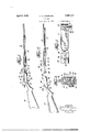
Fig. 1 is a side elevation of a rifle embodying the invention.
Fig. 2 is a similar view with the barrel portion disconnected from the stock portion.
Fig. 3 is a section on the line 3-3 of Fig. 1.
Fig. 4 is a plan view partially broken away of the stock portion.
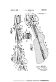
5 is fragmentary side elevation with the detachable side wall of the receiver removed.
Fig. 6 is a fragmentary reverse view of the barrel portion.
Fig. 7 is a fragmentary viewof the stock portion partially in section and with the detachable side wall removed, and
Fig. 8 is a section on the line 88 of Fig. 7.
The rifle comprises a standard stock 10 and a barrel 11 connected by means of a twopart receiver 12. The magazine 13 is supported beneath the barrel 11 and communicates with the receiver 12. An action rod handie 14: is slidably supported by the magazine 13 and is connected to an action rod 15 which extendsinto the receiver through the front wall thereof. A portion 12 of the receiver'is carried by the barrel and is provided with side walls 16. A spacing pin 16 is arranged between the side walls 16 and maintains said walls properly spaced. The remainingportion 12 of the receiver is carried by the stock 12 "and is provided with an integral side wall 05 17 and a detachable side plate 17 a which overlie the walls 16 and engage the portion 12.
The portion 12 is provided with recesses 18 within which are received prongs 19 provided on the stock portion 12 The barrel portion 12 and stock portion 12 are provided near their front ends with co-acting oblique surfaces 20 and 20*, the contacting of which is effective to draw the prongs 19 into the recesses 18. The two parts 12 and 12" are assembled by inserting the prongs '19 into the recesses 18 with the barrel portion and stock portion angularly related and then swinging the same to bring the co-acting surfaces 20 and 20 into contact. The barrel 8C portion 12" is provided with an oblique slot 21 which receives a bolt 22 carried by'the walls of the stock portion 12 One end of this bolt lies substantially flush with the side wall 17 and is fixed thereto, while theother end projects through a hole in the removable side plate 17*. A nut 23 is threaded on the projecting end of the bolt 22 and has a portion 24 of reduced diameter adapted topass through the hole in the side plate 17 and into a countersunk recess at the end ofthe slot 21. This nut, when the portion 24 is engaged in the countersunk recess, effectively prevents relative angular movement of the stock and barrel portions, thereby holding the same in assembled relation.
The breech bolt 25 is operated in the wellknown manner by the action rod '15'to which it is connected. The action rod 15 lies in a slot 26 in a side wall-l6 and is provided with a lug 27 which projects into a slot 28 provided for it in the breech bolt. The carrier 29 is pivotally supported between the walls 16 by a pin 80. A. hammer 31 is rotatably mounted on a stud 82 supported by a wall of the stock portion 12 and a trigger 33 is pivotally supported by the stock portion and cooperates with the hammer in the usual manner. The receiver is provided wita a tang portion which comprises a tubular member 34 provided with a head 35 having a tapering por tion which is received within a corresponding recess formed partly in the rear wall of the stock portion and partly in the removable side plate 17. A bolt 36 is provided in the rear Wall of the stock and is threaded into the head 35 and a bolt 36 passes through the side plate and is also threaded into the head 35.
The tubular member extends rearwardly from the stock portion and in it is provided the hammer actuating spring 37, the front end of which engages aplunger 38 slidably mounted in the tubular member. The front end of the plunger 88 is recessed and receives one end of a rod 39, the other end of which is received within a vertical recess 40 in the hammer 31. Near the rear end of the stock 10 there is provided a bushing 41 through.
wvhich extends a bolt 42 which is threaded into the rear end of the tubular member 34;. The stock portion 12 is provided around the tubular member 3a with a recess into which projects the nose of the stock 10. The stock 10 is held to the stock portion 12 through the medium of a bolt l2 and tubular member 34. The side plates 17 may be removed by taking out the bolt 36 and screwing off the nut 23 which is replaced aft r the plate has been removed. The side plate 17 when removed, uncovers the corresponding side wall 16 and also the hammer and trigger which may be removed while the remaining parts are retained in assembled relation. In order to take out the hammer with the side wall removed, the hammer is moved into cocked position, thus forcing the plunger 88 into the tubular member 37. A. suitable tool is then inserted through the hole for the bolt 36 to retain the plunger within the tubular member. The hammer is then returned to firing position whereupon the bar 39 may be easily lifted out after which the hammer may be slid off the stud 32. This feature is v ery helpful in connection with making the final adjustments on the hammer and trigger for obtaining the proper pull on the trigger and also for making other changes incidental to the final adjustment of the gun.
It is of course understood that various modifications may be made in the structure above described, without in any way departing from the spirit of the invention as de fined in the appended claims.
I claim:
1. In a firearm, a receiver comprising a barrel portion and a stock portion, recesses at the rear end of said barrel portion, prongs n d stock portion fitting in said recesses, co-acting longitudinally oblique surfaces on the stock and barrel portions at the front end thereof adapted upon Contacting to pull said prongs longitudinally into said recesses, and means for locking said barrel and stock portions against relative angular movement.
2. in a firearm, a receiver comprising a.
barrel portion and a stock port-ion, said barrel portion being provided with side walls underlying the side walls of the stock portion, recesses at the rear end of the said barrel portion, prongs on said stock portion fitting in said recesses, co-acting longitudinally oblique surfaces on said stock and barrel portions at the front end thereof adapted upon contacting to pull said prongs longiudinally into said recesses, and means for locking the barrel and stock portions against relative angular movement. in a firearm, a receiver comprising a barrel portion and a stock portion, recesses at the rear end of said barrel portion, prongs on said stock porlion fitting in said recesses, co-acting longitudinally oblique surfaces on the stock and barrel portions at the front end thereof adapted upon contacting to pull said prongs longitudinally into said recesses, a bolt carried by the side walls cf the stock portion, an oblique slot in the barrel portion for receivin said bolt, and a nut threaded on said bolt, a portion of said nut being received within a recess in said barrel portion to prevent relative angular movement of said stock and barrel portions.
l. In a firearm, a receiver comprising a barrel portion and a stock portion, said barrel portion being provided with side walls underlying the side walls of the stock portion, recesses at the rear end of the said bar-- rel portion, prongs on said stock portion fitting in said recesses, co-acting longitudinally oblique surfaces on said stock and barrel porlions at the front end thereof adapted upon contactin to pull said prongs longitudinally into said recesses, a bolt carried by the side walls of the st ck portion, an oblique slot in the barrel portion for receivsaid bolt, and a nut threaded on said belt, a portion of said bolt being received within a recess in said barrel portion to prevent relative angular movement of said stock and barrel portions.
In a firearm, a receiver comprising a barrel portion, a stock portion, recesses at the rear end of said barrel portion, prongs at the rear end of said stock portion fitting in said recesses, co-acting longitudinally oblique surfaces on said stock and barrel portions on the front end thereof adapted upon contacting to pull said prongs longitudinally into said recesses, means for locking said barrel and stock portions against relative angular movement, a trigger and a hammer pivoted to said stock portion, a breech bolt slidably mounted in said barrel portion, and a carrier pivotally supported by said barrel portion.
6. In a firearm, a receiver comprising a barrel portion, a stock portion, recesses at the rear end of said barrel portion, prongs at the rear end of said stock portion fitting in said recesses, co-acting longitudinally oblique surfaces on said stock and barrel portions on the front end thereof adapted upon contacting to pull said prongs longitudinally into said recesses, means for locking said barrel and stock portions against relative angular movement, a trigger and a hammer pivoted to said stock portion, a breech bolt slidably mounted in said barrel portion, and a carrier pivotally supported by said barrel portion, one of the side walls of the stool: portion being removable to uncover the trigger and hammer.
7. In a firearm, a receiver comprising a barrel portion, a stock portion, said barrel portion being provided with walls under lying the side plates of the stock portion, recesses at the rear end of said barrel portion, prongs at the rear end of said stock port-ion fitting in said recesses, co-acting longitudinally oblique surfaces on said stock and barrel portions at the front end thereof adapted on contacting to pull said prongs longitudinally into said recesses, means for locking said barrel and stocli portions against relative angular movement, a ham mer, and a trigger pivotally supported by said stock portion, a breech bolt slidably supported by said barrel portion, and a carrier pivotally supported by said barrel portion.
8. In a firearm, a receiver comprising a barrel portion, a stock portion, said barrel portion being provided with walls underlying the side plates of the stock portion, recesses at the rear end of said barrel portion, prongs at the rear end of saic stock portion fitting in said recesses, co-acting longitudinally oblique surfaces on said stock and bar rel portions at the front end thereof adapted on contacting to pull said prongs longitudinally into said recesses, means for locking said barrel and stock portions against relative angular movement, a hammer and a trigger pivotally supported by said stock portion, a breech bolt slidably supported by said barrel portion, and a carrier pivotally supported by said barrel portion, one of the side plates of the stock portion being removable to uncover the corresponding side wall and also the trigger and hammer.
9. In a firearm, a receiver comprising a barrel portion, a stock portion, said barrel portion being provided with side walls underlying the side plates of the stock portion, recesses at the rear end of said barrel portion, prongs on said stock portion extending into said recesses, co-acting longitudinally oblique surfaces on the stock-and barrel portions at the front end thereof adapted upon contacting to pull said prongs longitudinally into said recesses, means for locking the barrel and stock portions against relative angular movement, an action slide extending into said receiver, said slide being received in a slot in a side wall of said barrel portion.
10. In a firearm, a receiver comprising stock and barrel portions having interengaging projections and recesses at one end, coacting longitudinally oblique surfaces on said stock and barrel portions at the other end adapted upon contacting to draw said projections and recesses longitudinally into engagement, and means for locking said barrel and stock portions against relative angular movement.
11. In a firearm, a receiver comprising stock and barrel portions having interenga-ging projections and recesses at one end, co-acting longitudinally oblique surfaces on said stock and parallel portions at the other end adapted upon contacting todraw said projections and recesses longitudinally into engagement, a bolt carried by said stock portion at the other end, an oblique slot in the barrel portion for receiving said bolt, and a nut threaded on said bolt for clamping said portions in assembled relation.
12. In a firearm, a receiver comprising a barrel portion and a stock portion, said barrel portion being provided with side walls underlying the side plates of the stock portion and having an open top, a breech bolt slidably supported by said barrel portion, an action slide arranged in a slot in a side wall of said barrel portion and closing the open top thereof and operatively connected to said breech bolt, and a carrier pivotally mounted between said walls.
7 13. In a. firearm, a receiver, a tapering rectangular recess in the rear of said receiver, a tubular tang having a tapering rectangular head received Within said recess, means to lock said head in said recess, a spring-pressed plunger in said tang, a hammer pivoted in said receiver, and a rod having one end seated in a recess in the end of said plunger and its other end seated in recess in said hammer.
1.4. In a firearm, a receiver having an eX- ternal recess in its rear Wall, a stock having a reduced portion extending into said recess, a tapered rectangular internal recess in the rear wall of said receiver, a tubular tang having a tapered rectangular head fitting in said recess, a bolt carried by said stock and threaded into said tang, a spring pressed plunger in said tang, a hammer pivotally mounted in said receiver, and a bar having one end seated in a recess in said plunger and the other end seated in a recess in said hammer.
15. In a firearm, a receiver having an external recess in itsrear wall, a stock having a reduced portion extending into said recess, a tapered rectangular internal recess in the rear wall of said receiver, a tubular tang having a tapered rectangular head fitting in said recess, a bolt carried by said stock and threaded into said tang, a spring pressed plunger in said tang, a hammer pivotally mounted in said receiver, and a bar having one end seated in a recess in said plunger and the other end seated in a recess in said hammer, one side plate of said receiver being removableto uncover the head of said tang and also said hammer, and a bolt passing through said side plate and threaded into said head for detachably connecting said side plate to said receiver.
16. In a firearm, a receiver comprising a barrel portion and a stock portion, said barrel portion being provided with side walls and having an open top, a breech bolt slidably supported by said barrel portion and being adapted to close the open top thereof, a carrier pivotally mounted between said walls, and an action slide arranged in a slot in a side wall of said barrel portion and be ing operatively connected to said breech bolt and carrier.
17. In a firearm, a receiver comprising a barrel portion and a stock portion, said barrel portion being provided with side walls, and having an open top, a breech bolt slidably supported by said barrel portion and being adapted to close the open top thereof, a carrier pivotally mounted between said walls, an action slide arranged in a slot in a side wall of said barrel portion and being operatively connected to said breech bolt and carrier, and a spacing member arranged between said side walls.
18. In a firearm, a receiver comprising a barrel portion having side walls, a stock portion having an integral side wall and an assembled side plate overlying the walls of the barrel portion, a tang portion having a head. seated in a recess formed partly in the rear wall of said stock portion and partly in said assembled side plate, and means for fastening said side plates to said stock portion.
In testimony whereof, I have signed my name to this specification.
CARL G. SWEBILIUS.
CERTIFICATE OF CORRECTION.
Patent No. 1,852,440. Granted April 1, 1932, t
CARL G. SWEBILIUS.
it is hereby certified that error appears in the printed specification of t above numbered patent requiring correction as follows: Page 3, lines 107 at 108, claim 12, strike out the words "and closing the open top thereof" and il sert same to follow the word "portion" in line 105, of same claim; and that the said Letters Patent should be read with these corrections therein that th same may conform to the record of the case in the Patent Office.
Signed and sealed this 17th day of May, A. D. 1932.
M. J. Moore, (Seal) Acting Commissioner of Patent CERTIFICATE or CORRECTION.
Patent No. 1,852,440. Granted April 1, 1932, to
CARL G. SWEBILIUS.
It is hereby certified that error appears in the printed specification of the above numbered patent requiring correction as follows: Page 3, lines 107 and 108, claim 12, strike out the words "and closing the open top thereof" and insert same to follow the word "portion" in line 105, of same claim; and that the said Letters Patent should be read with these corrections therein that the same may conform to the record of the case in the Patent Office.
Signed and sealed this 17th day of May, A. D. 1932.
M. J. Moore, (Seal) Acting Commissioner of Patents.
Priority Applications (1)
| Application Number | Priority Date | Filing Date | Title |
|---|---|---|---|
| US467469A US1852440A (en) | 1930-07-12 | 1930-07-12 | Firearm |
Applications Claiming Priority (1)
| Application Number | Priority Date | Filing Date | Title |
|---|---|---|---|
| US467469A US1852440A (en) | 1930-07-12 | 1930-07-12 | Firearm |
Publications (1)
| Publication Number | Publication Date |
|---|---|
| US1852440A true US1852440A (en) | 1932-04-05 |
Family
ID=23855831
Family Applications (1)
| Application Number | Title | Priority Date | Filing Date |
|---|---|---|---|
| US467469A Expired - Lifetime US1852440A (en) | 1930-07-12 | 1930-07-12 | Firearm |
Country Status (1)
| Country | Link |
|---|---|
| US (1) | US1852440A (en) |
Cited By (2)
| Publication number | Priority date | Publication date | Assignee | Title |
|---|---|---|---|---|
| US20110179687A1 (en) * | 2008-06-27 | 2011-07-28 | Fabbrica D'armi Pietro Beretta S.P.A. | Stock bolt of a firearm equipped with a damping mechanism |
| US9188399B1 (en) * | 2014-10-31 | 2015-11-17 | Smith & Wesson Corp. | Receiver catch |
-
1930
- 1930-07-12 US US467469A patent/US1852440A/en not_active Expired - Lifetime
Cited By (3)
| Publication number | Priority date | Publication date | Assignee | Title |
|---|---|---|---|---|
| US20110179687A1 (en) * | 2008-06-27 | 2011-07-28 | Fabbrica D'armi Pietro Beretta S.P.A. | Stock bolt of a firearm equipped with a damping mechanism |
| US8677664B2 (en) * | 2008-06-27 | 2014-03-25 | Fabbrica D'armi Pietro Beretta S.P.A. | Stock bolt of a firearm equipped with a damping mechanism |
| US9188399B1 (en) * | 2014-10-31 | 2015-11-17 | Smith & Wesson Corp. | Receiver catch |
Similar Documents
| Publication | Publication Date | Title |
|---|---|---|
| US3722358A (en) | Combined single and double action firing mechanisms for pistols and kits for converting single-action pistols | |
| US3584533A (en) | Autoloading firearm of the blowback type | |
| US20110289813A1 (en) | Multi-caliber conversion kits for semi-automatic pistols | |
| US4570369A (en) | Cylindrical, falling breech block, rifle action | |
| RU2005113759A (en) | MULTI-LOADED WEAPONS | |
| US2548622A (en) | Firing mechanism for submachine guns | |
| US3176423A (en) | Revolver firing mechanism | |
| US1852440A (en) | Firearm | |
| US1661949A (en) | Interchangeable rifle and shotgun barrel | |
| US3187454A (en) | Revolver cylinder stop | |
| NO328662B1 (en) | Load the repeater weapon | |
| US2765561A (en) | Repeating rifle having trigger mechanism on finger lever | |
| US2377703A (en) | Firearm | |
| US2050038A (en) | Repeating firearm | |
| US2765559A (en) | Carrier mechanism for guns | |
| US2098562A (en) | Firearm | |
| US2462889A (en) | Cartridge case extractor | |
| US2125571A (en) | Gun | |
| US1580968A (en) | Firearm with screwed barrel detachable by hand or permanently fixed | |
| US2289098A (en) | Breech-loading firearm | |
| US1476125A (en) | Target pistol | |
| US3444640A (en) | Firing mechanism for double-barrelled shotguns | |
| US1513658A (en) | Fore-end construction for firearms | |
| US1246984A (en) | Firearm. | |
| US2627687A (en) | Combination pivoting and sliding block firearm action |