US185243A - Improvement in harvesters - Google Patents
Improvement in harvesters Download PDFInfo
- Publication number
- US185243A US185243A US185243DA US185243A US 185243 A US185243 A US 185243A US 185243D A US185243D A US 185243DA US 185243 A US185243 A US 185243A
- Authority
- US
- United States
- Prior art keywords
- pivoted
- attached
- lever
- frame
- bar
- Prior art date
- Legal status (The legal status is an assumption and is not a legal conclusion. Google has not performed a legal analysis and makes no representation as to the accuracy of the status listed.)
- Expired - Lifetime
Links
- 241001124569 Lycaenidae Species 0.000 title description 2
- 238000010276 construction Methods 0.000 description 1
Images
Classifications
-
- F—MECHANICAL ENGINEERING; LIGHTING; HEATING; WEAPONS; BLASTING
- F16—ENGINEERING ELEMENTS AND UNITS; GENERAL MEASURES FOR PRODUCING AND MAINTAINING EFFECTIVE FUNCTIONING OF MACHINES OR INSTALLATIONS; THERMAL INSULATION IN GENERAL
- F16H—GEARING
- F16H21/00—Gearings comprising primarily only links or levers, with or without slides
- F16H21/10—Gearings comprising primarily only links or levers, with or without slides all movement being in, or parallel to, a single plane
- F16H21/16—Gearings comprising primarily only links or levers, with or without slides all movement being in, or parallel to, a single plane for interconverting rotary motion and reciprocating motion
- F16H21/18—Crank gearings; Eccentric gearings
- F16H21/22—Crank gearings; Eccentric gearings with one connecting-rod and one guided slide to each crank or eccentric
- F16H21/32—Crank gearings; Eccentric gearings with one connecting-rod and one guided slide to each crank or eccentric with additional members comprising only pivoted links or arms
-
- Y—GENERAL TAGGING OF NEW TECHNOLOGICAL DEVELOPMENTS; GENERAL TAGGING OF CROSS-SECTIONAL TECHNOLOGIES SPANNING OVER SEVERAL SECTIONS OF THE IPC; TECHNICAL SUBJECTS COVERED BY FORMER USPC CROSS-REFERENCE ART COLLECTIONS [XRACs] AND DIGESTS
- Y10—TECHNICAL SUBJECTS COVERED BY FORMER USPC
- Y10T—TECHNICAL SUBJECTS COVERED BY FORMER US CLASSIFICATION
- Y10T74/00—Machine element or mechanism
- Y10T74/18—Mechanical movements
- Y10T74/18056—Rotary to or from reciprocating or oscillating
- Y10T74/18176—Crank, pitman, lever, and slide
Definitions
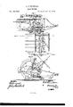
- Figure 1 is a top view of my improved machine, part being broken away to show the construction.
- Fig. 2 is a vertical section of the same taken through the line a; m, Fig. 1.
- the object of this invention is to furnish an improved machine which shall be so constructed that it may be run at less speed than the ordinary machines, and may thus be more durable and of lighter draft, while doing good work.
- A is the frame of the machine, in bearings attached to which revolves the axle B.
- the drive-wheel O which has an internally-toothed gear-wheel, D, formed upon or attached to its inner side.
- D gear-wheel
- the gear-wheel D meshes the teeth of the small gear-wheel E, placed upon the outer end of the shaft F, which revolves in bearings attached to the frame A, has a crank,f formed upon its middle part, and a weighted arm, f attached to its inner end.
- the crank f and the weighted arm f project in opposite directions tobalance each other.
- a connecting-rod To the crank f is pivoted the forward end of a connecting-rod, G, the other end of which is pivoted to the side of a bar, H, that slides in bearings attached to the frame A, and to the otherside of said bar is pivoted the rear end of a connecting-rod, I.
- the forward end of the connecting-rod I is pivoted to the end of the long arm of a bent or elbow lever, J, which is pivoted at its angle to the frame A, and is strengthened by a bracebar connecting its ends and making it a triangular lever.
- To the end of the short arm of the bent lever J To the end of the short arm of the bent lever J is pivoted the end of a short connecting-rod, K, the other end of which is pivoted to the end of the sickle-bar L.
- the crank f and the arms of the lever J are made of such a relative length that the sickles M,
- the sickle-bar L may move through the space of, and cut the grain'against, two of the fingers N, attached to the cutter-bar O.
- the fingers N incline downward a little, so that when the cutter-bar O is tilted to cut lodged grain, the said fingers may hold the stalks until they are out.
- a short crank To the rear side of the cutter-bar O is hinged the shaft of the dropper P, to the inner end of which is attached a short crank, 12.
- To the crank 12 is pivoted the forward end of a connecting-rod, Q, that passes back through guides attached to the frame A, and its rear end is bent upward, and is pivoted to the rear end of a connecting-rod, R, the forward end of which is pivoted to the crank S of the foot-lever T.
- the foot-lever S T is pivoted to the case U that covers and protects the working-mechanism of the machine, in such a positionthat it may be conveniently reached and operated by the driver from his seat A.
- To the forward frame, V to the forward angle of which is hinged the tongue B.
- To the forward angle of the frame V is pivoted the standard G of the caster-wheel D, by which the said frame V and tongue B are supported.
- To the forward end of the triangular frame V is pivoted the forward end of the connecting-rod W, the rear end of which is pivoted to the lever X.
- the lower end of the lever X is pivoted to the frame A, and with said lever is connected a lever spring-pawl, E, engaging with the teeth of a curved toothed bar, F, along which said lever X moves.
- a pulley, G around which passes a band, H, which also passes around a pulley, I, attached to the shaft of the reel Y.
- the shaft of the reel Y revolves in bearings in the upper end of the post Z, the lower end of which is attached to the frame A.
- the outer end of the cutter-bar O is supported by a wheel, J, the standard K of which passes through a keeper, L, attached to the divider M, and its end is pivoted to a bar, N, that slides up and down in a groove in said divider, and is secured in place, when adjusted, by a screw or bolt.
- the gear-wheel E slides upon the shaft F, is made to carry said shaft with it by a pin and notch, and is thrown into and out of gear with the said pin the balanced crank-shaft F, the slide H, the
Landscapes
- Engineering & Computer Science (AREA)
- General Engineering & Computer Science (AREA)
- Mechanical Engineering (AREA)
- Harvester Elements (AREA)
Description
o. s. KNUDSON. HARVESTER.
No.185,243, Patented 1365.12, 1876.
momma THE GRAPH [C CO. NM
OLE S. KNUDSON, OF HOUSTON, MINNESOTA.
- IMPROVEMENT IN HARVESTERS.
Specification forming part of Letters Patent No. 185,243, dated December 12, 1876 application filed July 15, 1876.
. To all whom it may concern:
Be it known that I, OLE S. KNUDSQN, of Houston, in the county of Houston and State of Minnesota, have invented a new and useful Improvement in Reapers and Mowers, of which the following is a specification:
Figure 1 is a top view of my improved machine, part being broken away to show the construction. Fig. 2 is a vertical section of the same taken through the line a; m, Fig. 1.
Similar letters of reference indicate corresponding parts.
The object of this invention is to furnish an improved machine which shall be so constructed that it may be run at less speed than the ordinary machines, and may thus be more durable and of lighter draft, while doing good work.
The invention will first be described in connection with the drawing, and then pointed out in the claim.
A is the frame of the machine, in bearings attached to which revolves the axle B. To the outer end of the axle B is attached the drive-wheel O, which has an internally-toothed gear-wheel, D, formed upon or attached to its inner side. Into the teeth of the gear-wheel D mesh the teeth of the small gear-wheel E, placed upon the outer end of the shaft F, which revolves in bearings attached to the frame A, has a crank,f formed upon its middle part, and a weighted arm, f attached to its inner end. The crank f and the weighted arm f project in opposite directions tobalance each other. To the crank f is pivoted the forward end of a connecting-rod, G, the other end of which is pivoted to the side of a bar, H, that slides in bearings attached to the frame A, and to the otherside of said bar is pivoted the rear end of a connecting-rod, I. The forward end of the connecting-rod I is pivoted to the end of the long arm of a bent or elbow lever, J, which is pivoted at its angle to the frame A, and is strengthened by a bracebar connecting its ends and making it a triangular lever. To the end of the short arm of the bent lever J is pivoted the end of a short connecting-rod, K, the other end of which is pivoted to the end of the sickle-bar L. The crank f and the arms of the lever J are made of such a relative length that the sickles M,
attached to the sickle-bar L, may move through the space of, and cut the grain'against, two of the fingers N, attached to the cutter-bar O. The fingers N incline downward a little, so that when the cutter-bar O is tilted to cut lodged grain, the said fingers may hold the stalks until they are out. To the rear side of the cutter-bar O is hinged the shaft of the dropper P, to the inner end of which is attached a short crank, 12. To the crank 12 is pivoted the forward end of a connecting-rod, Q, that passes back through guides attached to the frame A, and its rear end is bent upward, and is pivoted to the rear end of a connecting-rod, R, the forward end of which is pivoted to the crank S of the foot-lever T. The foot-lever S T is pivoted to the case U that covers and protects the working-mechanism of the machine, in such a positionthat it may be conveniently reached and operated by the driver from his seat A. To the forward frame, V, to the forward angle of which is hinged the tongue B. To the forward angle of the frame V is pivoted the standard G of the caster-wheel D, by which the said frame V and tongue B are supported. To the forward end of the triangular frame V is pivoted the forward end of the connecting-rod W, the rear end of which is pivoted to the lever X. The lower end of the lever X is pivoted to the frame A, and with said lever is connected a lever spring-pawl, E, engaging with the teeth of a curved toothed bar, F, along which said lever X moves. To the inner end of the axle B is attached a pulley, G, around which passes a band, H, which also passes around a pulley, I, attached to the shaft of the reel Y. The shaft of the reel Y revolves in bearings in the upper end of the post Z, the lower end of which is attached to the frame A. The outer end of the cutter-bar O is supported by a wheel, J, the standard K of which passes through a keeper, L, attached to the divider M, and its end is pivoted to a bar, N, that slides up and down in a groove in said divider, and is secured in place, when adjusted, by a screw or bolt. The gear-wheel E slides upon the shaft F, is made to carry said shaft with it by a pin and notch, and is thrown into and out of gear with the said pin the balanced crank-shaft F, the slide H, the
triangular lever J, and the connecting-rods G l K with the drive-wheel O, the frame A, and the sickle-bar L, substantially as herein shown and described.
OLE s. KNUDSON.
Witnesses:
F. N. Goonmon, E. J. Goonmon.
Publications (1)
| Publication Number | Publication Date |
|---|---|
| US185243A true US185243A (en) | 1876-12-12 |
Family
ID=2254648
Family Applications (1)
| Application Number | Title | Priority Date | Filing Date |
|---|---|---|---|
| US185243D Expired - Lifetime US185243A (en) | Improvement in harvesters |
Country Status (1)
| Country | Link |
|---|---|
| US (1) | US185243A (en) |
-
0
- US US185243D patent/US185243A/en not_active Expired - Lifetime
Similar Documents
| Publication | Publication Date | Title |
|---|---|---|
| US185243A (en) | Improvement in harvesters | |
| US29610A (en) | Improvement in grain-harvesters | |
| US193614A (en) | Improvement in harvesters | |
| US180004A (en) | Improvement in reapers and mowers | |
| US123631A (en) | Improvement in harvesters | |
| US152379A (en) | Improvement in harvesters | |
| US236231A (en) | Attachment for reapers and mowers | |
| US118315A (en) | Improvement in harvesters | |
| US195038A (en) | Improvement in harvesters | |
| US171010A (en) | Improvement in self-rakes for reapers | |
| US204698A (en) | Improvement in harvester-droppers | |
| US52351A (en) | Improvement in harvesters | |
| US120027A (en) | Improvement in harvesters | |
| US422162A (en) | Mowing-machine | |
| US666111A (en) | Lawn-mower. | |
| US183275A (en) | Improvement in harvester-droppers | |
| US35970A (en) | Improvement in harvesters | |
| US12769A (en) | Improvement in harvesters | |
| US172050A (en) | Improvement in harvesters | |
| US138830A (en) | Improvement in harvesters | |
| US257858A (en) | William gause | |
| US135729A (en) | Improvement in harvesters | |
| US152211A (en) | Improvement in harvester-droppers | |
| US129501A (en) | Improvement in harvesters | |
| US317815A (en) | Harvester |