US1852424A - Automatic radio-phonograph switch - Google Patents
Automatic radio-phonograph switch Download PDFInfo
- Publication number
- US1852424A US1852424A US368968A US36896829A US1852424A US 1852424 A US1852424 A US 1852424A US 368968 A US368968 A US 368968A US 36896829 A US36896829 A US 36896829A US 1852424 A US1852424 A US 1852424A
- Authority
- US
- United States
- Prior art keywords
- switch
- pick
- radio
- tube
- phonograph
- Prior art date
- Legal status (The legal status is an assumption and is not a legal conclusion. Google has not performed a legal analysis and makes no representation as to the accuracy of the status listed.)
- Expired - Lifetime
Links
Images
Classifications
-
- H—ELECTRICITY
- H01—ELECTRIC ELEMENTS
- H01H—ELECTRIC SWITCHES; RELAYS; SELECTORS; EMERGENCY PROTECTIVE DEVICES
- H01H19/00—Switches operated by an operating part which is rotatable about a longitudinal axis thereof and which is acted upon directly by a solid body external to the switch, e.g. by a hand
- H01H19/54—Switches operated by an operating part which is rotatable about a longitudinal axis thereof and which is acted upon directly by a solid body external to the switch, e.g. by a hand the operating part having at least five or an unspecified number of operative positions
- H01H19/60—Angularly-movable actuating part carrying no contacts
- H01H19/62—Contacts actuated by radial cams
Definitions
- This invention relates to reproducing sys tems and has for its object the provision of a simple and efiieient device which can be per manently installed in a radio set so as to con nect the radio set to a phonograph providing automatic means for disconnecting the radio receiving tubes when the phonograph is operated and for automatically connecting the rapfdio circuits when the phonograph is shut
- my Patent No. 1,645,491 I have shown a simple system which has been very successful. This system however has the disadvantage that to change from radio reproduction to phonograph reproduction one must lift out the detector tube and insert in the socket a special handle and naturally when changing back to the radio use the plug or handle must be taken out and the tube reinserted which takes some little time.
- the primary object of the invention is therefore to provide a device which may be permanently connected to the radio set and 0 in the use of which it is not necessary to remove any tube or to break any connection in any part by any special act in changing either from radio to phonograph or from phone graph to radio.
- a further object of the invention lies in the provision of automatic means associated with the phonograph pickup volume control for switching the connections from radio to phonograph and vice versa.
- This rotary resistance control in 01f position connects the plate rong of thedetector tube to the corresponding contact of the socket but when the resistance is rotated the plate contact of the detector socket is connected to the pick-up so that the plate prong of the detector tube is disconnected.
- the pick-up 10 is of any desired commercial type made substantially identical with the pick-up shown in my patent heretofore mentioned.
- This pick-up is connected by the wires ll and 12 with the movable arm 14 of the phonograph volume control which is merely a resistance.
- the resistance wire 15 is connected by the wire 16 to the other binding post of the pick-up and is also connected thru the wire 17 to the lower contact 18 of a single pole double throw switch indicated as a whole by the numeral 20 and of which the other fixed contact is 19 and is connected by the wire 21 to a spring contact 22 which engages the plate prong 23 of the radio tube 24.
- Each of the other prongs of the radio tube engage spring contacts of the adaptor 25 such as 26, 27 and 28 on alined sockets 30, 31 and 32 of the adaptor which fits into the radio set in the same manneras the detector tube would if the adaptor were absent.
- the prong 33 however which fits into the plate socket of the set is connected by the wire 34 with the movable blade 35 of the switch 20, this blade engagingthe contact 19 to connect the plate prong of the tube direct to the plate socket of the radio set or to engage the contact 18 whichwill disconnect the plate prong of the tube and will connect the adaptor plate prong 33'with the wire 17 leading to the pick-up.
- a by-pass condenser 37 is placed between the filament throw switch connecting the two; split con:
- a. double throw switch means govprong 32 and the pick-up in the same manner as in my patent.
- the operation is as follows :
- the adaptor 25 is inserted into the detector socket and when so positioned the detector tube is then inserted into the adaptor this connection being relatively permanent.
- the volume control 14 of the phonograph device is in the position illustrated in the figure at which time the cammed end 38 of the spring blade 35 of the switch 20'is-received within the recess 39 of-t'he volume control shaft or pre-ierably a collar on such shaft and the springblade 35 is therefore in engagement with the contact 19 directly connecting the 'plate'prong' 23 of the tube with the plate prong 33.
- V In combination, a pick-up, means for electrically connecting the: pick-up to a circuit of a radio set, a volume control connected to the terminals-of the pick-up, and means governed by the position of thecontrol for connecting and disconnecting: the ⁇ pick-up socket, andvadapted inthe'oth'er position .to connect said socket with said pickup, a variahlecontrolo-for the pick-up, and means operated by said control for throwing the switch so as to disconnect the :tube'from theiset .and :to :substitute therefor said pick-up.
- an adaptor having a split connection for one-of the prongs of a of the other prongs, a si'ngle pole double nections, -a pick-upconne'cted to one of the direct connected prongs andv to the free contact of said switch, a volume control connected .to .said pickup, .a handle for varying the-control, means connecting said handle and sai'd switch whereby the latter is operated at one position-ofsaid control;
- a' rotary member for controlling said emedby isaid rotary memberzfor throwing "-tlie blade ofsaid's-witch', and means connectswitch. g '7.
- an adaptor having a 'plurality of prongs correspondingin number to the prongs of a radio tube, means for electrically connecting a filament prong of the tubewiththefila-- ment prong of the-adaptor, a-single'pol-e double throw switch, means for connectingthe plate prong of theadaptor with'the blade ojf the switch and connecting the plate prong of; the tube with one contact oi saidlswitch, a
- An accessory for connecting a reproducer to a radio set com risin in-combinaradio tube and direct-econnections ior each p g tion, transmitter terminals, an adapter' havingprongs arranged'tofitinthe socketsprovided' for a certain tube in the set, sockets in said'ada-ptor corresponding to the prongs of said tube, contacts on some of said adaptor prongs positioned in the adaptor sockets'to engage the correspondingprongs of the' tube "adaptor prong connected'thru one side ofsaid switch to its corresponding adaptor socket terminal, the other'side of said switch being connected-to asecondtransmitterterminal, a.
- variable impedance connected to said transmitter terminals, means for varying the impedance, said means being connected to the switch whereby when the transmitter terminals are connected to the set by the switch the non-contact-carrying prong is disconnected from its corresponding adaptor socket terminal.
- connector terminals means for electrically connecting the connector terminals to a circuit of a radio set, a variable resistance connected to said terminals and means for Varying said resistance, and a means governed by the position of said resistance varying means for connecting and disconnecting the terminals and the set.
Landscapes
- Details Of Connecting Devices For Male And Female Coupling (AREA)
Description
April 1932- LE ROY J. LEISHMAN 1,852,424
AUTOMATIC RADIO PHONOGRAPH SWITCH Filed June 6, 1929 LeRo JLeisluna/w,
gwuentoo Patented Apr. 5, 1932 UNITED STATES LE ROY J. LEISHMAN, LOS ANGELES, CALIFORNIA AUTOMATIC RADIO-PHONOGRAPH SWITCH Application filed June a, 1929. Serial No. 368,968.
This invention relates to reproducing sys tems and has for its object the provision of a simple and efiieient device which can be per manently installed in a radio set so as to con nect the radio set to a phonograph providing automatic means for disconnecting the radio receiving tubes when the phonograph is operated and for automatically connecting the rapfdio circuits when the phonograph is shut In my Patent No. 1,645,491 I have shown a simple system which has been very successful. This system however has the disadvantage that to change from radio reproduction to phonograph reproduction one must lift out the detector tube and insert in the socket a special handle and naturally when changing back to the radio use the plug or handle must be taken out and the tube reinserted which takes some little time. I have also placed on the market a small disk which is inserted within the detector tube socket but while this is an improvement over theearlier system of removing the handle it still is neces sary to detune the set to prevent radio music from coming thru and interfering with the phonographic reproduction and furthermore in changing back to radio reception it is necessary to remove a phone tip from its tip jack somewhere between the disk and the volume control of the phonographaccessory in order to prevent the resistance of this accessory and the pick-up from being shunted across the detector tube which would naturally have the effect of cutting down the volume given by the loud speaker.
The primary object of the invention is therefore to provide a device which may be permanently connected to the radio set and 0 in the use of which it is not necessary to remove any tube or to break any connection in any part by any special act in changing either from radio to phonograph or from phone graph to radio. A further object of the invention lies in the provision of automatic means associated with the phonograph pickup volume control for switching the connections from radio to phonograph and vice versa. This rotary resistance control in 01f position connects the plate rong of thedetector tube to the corresponding contact of the socket but when the resistance is rotated the plate contact of the detector socket is connected to the pick-up so that the plate prong of the detector tube is disconnected.
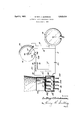
In the drawing The figure shows a simple embodiment of the invention.
The pick-up 10 is of any desired commercial type made substantially identical with the pick-up shown in my patent heretofore mentioned. This pick-up is connected by the wires ll and 12 with the movable arm 14 of the phonograph volume control which is merely a resistance. The resistance wire 15 is connected by the wire 16 to the other binding post of the pick-up and is also connected thru the wire 17 to the lower contact 18 of a single pole double throw switch indicated as a whole by the numeral 20 and of which the other fixed contact is 19 and is connected by the wire 21 to a spring contact 22 which engages the plate prong 23 of the radio tube 24. Each of the other prongs of the radio tubeengage spring contacts of the adaptor 25 such as 26, 27 and 28 on alined sockets 30, 31 and 32 of the adaptor which fits into the radio set in the same manneras the detector tube would if the adaptor were absent. The prong 33 however which fits into the plate socket of the set is connected by the wire 34 with the movable blade 35 of the switch 20, this blade engagingthe contact 19 to connect the plate prong of the tube direct to the plate socket of the radio set or to engage the contact 18 whichwill disconnect the plate prong of the tube and will connect the adaptor plate prong 33'with the wire 17 leading to the pick-up. A by-pass condenser 37 is placed between the filament throw switch connecting the two; split con:
- system, a. double throw switch, means govprong 32 and the pick-up in the same manner as in my patent.
The operation is as follows :The adaptor 25 is inserted into the detector socket and when so positioned the detector tube is then inserted into the adaptor this connection being relatively permanent. In the ordinary use of the radio the volume control 14 of the phonograph device is in the position illustrated in the figure at which time the cammed end 38 of the spring blade 35 of the switch 20'is-received within the recess 39 of-t'he volume control shaft or pre-ierably a collar on such shaft and the springblade 35 is therefore in engagement with the contact 19 directly connecting the 'plate'prong' 23 of the tube with the plate prong 33. of
the adaptor and consequently engaged with the set in a normal way In turningthe volume control 14 to operative position to use-the phonograph the spring blade 35 of the. switch20 is cammeddownwardly as shown in the figure, automatically disconnecting the plate prong 23 of the tube and connecting the: adaptor prong 33 with the pick-upso that the circuit is then ex actlythe same as illustrated in my patent. WhatI-claimis: V 1.- In combination, a pick-up, means for electrically connecting the: pick-up to a circuit of a radio set, a volume control connected to the terminals-of the pick-up, and means governed by the position of thecontrol for connecting and disconnecting: the} pick-up socket, andvadapted inthe'oth'er position .to connect said socket with said pickup, a variahlecontrolo-for the pick-up, and means operated by said control for throwing the switch so as to disconnect the :tube'from theiset .and :to :substitute therefor said pick-up.
, 3. In combination, an adaptor having a split connection for one-of the prongs of a of the other prongs, a si'ngle pole double nections, -a pick-upconne'cted to one of the direct connected prongs andv to the free contact of said switch, a volume control connected .to .said pickup, .a handle for varying the-control, means connecting said handle and sai'd switch whereby the latter is operated at one position-ofsaid control;
.4. .In a .telegraphophone" reproducer' system, a' rotary member for controlling said emedby isaid rotary memberzfor throwing "-tlie blade ofsaid's-witch', and means connectswitch. g '7. Incom'binatioma pick-up,za volume=con'- throw switch, means forconnecting the plate prongof the a'daptor "w'rth the blade of the switch-and connecting the plate prong of the tube with one contact of said switch, a pick- ;up connected to the other contact of said switch, means forconnecting said pick-up with the filament prongs of the adaptor and tube, a variable resistance shunted acrossv pick-up, and means governed by th'ezposition of' the variable resistance. for operating? the trol therefor, means for connecting the pickup to a radio set, and means operated by the volume controlior' electrically connecting and disconnecting the pick-up to the set. 8; In a device of the character described, an adaptor having a 'plurality of prongs correspondingin number to the prongs of a radio tube, means for electrically connecting a filament prong of the tubewiththefila-- ment prong of the-adaptor, a-single'pol-e double throw switch, means for connectingthe plate prong of theadaptor with'the blade ojf the switch and connecting the plate prong of; the tube with one contact oi saidlswitch, a
pick-up connected to the other contact of said switch, means=-for connecting said pick up -"with the filament prongs of theadapt'orand tube, a variable resistance, and'meanfs governedby the position of the var iableresistmice for operating the switch.- r '9. An accessory for connecting a reproducer to a radio set com risin in-combinaradio tube and direct-econnections ior each p g tion, transmitter terminals, an adapter' havingprongs arranged'tofitinthe socketsprovided' for a certain tube in the set, sockets in said'ada-ptor corresponding to the prongs of said tube, contacts on some of said adaptor prongs positioned in the adaptor sockets'to engage the correspondingprongs of the' tube "adaptor prong connected'thru one side ofsaid switch to its corresponding adaptor socket terminal, the other'side of said =switch being connected-to asecondtransmitterterminal, a.
variable impedance "connected to said transmitter terminals, means for varying the impedance, said means being connected to the switch whereby when the transmitter terminals are connected to the set by the switch the non-contact-carrying prong is disconnected from its corresponding adaptor socket terminal.
10. In combination, connector terminals, means for electrically connecting the connector terminals to a circuit of a radio set, a variable resistance connected to said terminals and means for Varying said resistance, and a means governed by the position of said resistance varying means for connecting and disconnecting the terminals and the set.
In testimony whereof I aflix my signature.
LE ROY J. LEISHMAN.
Priority Applications (1)
| Application Number | Priority Date | Filing Date | Title |
|---|---|---|---|
| US368968A US1852424A (en) | 1929-06-06 | 1929-06-06 | Automatic radio-phonograph switch |
Applications Claiming Priority (1)
| Application Number | Priority Date | Filing Date | Title |
|---|---|---|---|
| US368968A US1852424A (en) | 1929-06-06 | 1929-06-06 | Automatic radio-phonograph switch |
Publications (1)
| Publication Number | Publication Date |
|---|---|
| US1852424A true US1852424A (en) | 1932-04-05 |
Family
ID=23453501
Family Applications (1)
| Application Number | Title | Priority Date | Filing Date |
|---|---|---|---|
| US368968A Expired - Lifetime US1852424A (en) | 1929-06-06 | 1929-06-06 | Automatic radio-phonograph switch |
Country Status (1)
| Country | Link |
|---|---|
| US (1) | US1852424A (en) |
Cited By (3)
| Publication number | Priority date | Publication date | Assignee | Title |
|---|---|---|---|---|
| US2559354A (en) * | 1950-06-02 | 1951-07-03 | Gauthier Crosby | Sound reproducing system and apparatus |
| US2655565A (en) * | 1950-04-12 | 1953-10-13 | Dale Belford | Radio-phonograph adapter |
| US2875278A (en) * | 1954-02-23 | 1959-02-24 | Oscar W Lucders | Socket adapter arrangement |
-
1929
- 1929-06-06 US US368968A patent/US1852424A/en not_active Expired - Lifetime
Cited By (3)
| Publication number | Priority date | Publication date | Assignee | Title |
|---|---|---|---|---|
| US2655565A (en) * | 1950-04-12 | 1953-10-13 | Dale Belford | Radio-phonograph adapter |
| US2559354A (en) * | 1950-06-02 | 1951-07-03 | Gauthier Crosby | Sound reproducing system and apparatus |
| US2875278A (en) * | 1954-02-23 | 1959-02-24 | Oscar W Lucders | Socket adapter arrangement |
Similar Documents
| Publication | Publication Date | Title |
|---|---|---|
| US4037186A (en) | Connecting and switching system, and switching apparatus suitable for use therein | |
| US1852424A (en) | Automatic radio-phonograph switch | |
| US1247672A (en) | Telephone-conductor. | |
| US2768234A (en) | Electrical switching apparatus | |
| US4095262A (en) | Lightning protection circuit | |
| US2440270A (en) | Electrical connector | |
| US1934498A (en) | Adapter unit | |
| US4841559A (en) | Telephone network interface tester | |
| US1959272A (en) | Adapter | |
| US2655565A (en) | Radio-phonograph adapter | |
| US2233848A (en) | Audiphone | |
| US1569869A (en) | Connecter switch | |
| US368221A (en) | Chables w | |
| US2180487A (en) | Detachable rectifier plug | |
| US1990388A (en) | Changeover device | |
| US1774646A (en) | Tube adapter | |
| US1697237A (en) | Electrical plug | |
| US1340955A (en) | Telephone set | |
| US1809125A (en) | Telephone set mounting | |
| US2174456A (en) | Electrical circuit for communication systems | |
| US2361880A (en) | Telephone set | |
| US1896550A (en) | Remote control apparatus for radio circuits | |
| US2835736A (en) | Remote control for television and radio apparatus | |
| US2264886A (en) | Phonograph control system | |
| US2448380A (en) | Selector switch for phonograph circuit |