US1852421A - Interlocking system for railroads - Google Patents
Interlocking system for railroads Download PDFInfo
- Publication number
- US1852421A US1852421A US467233A US46723330A US1852421A US 1852421 A US1852421 A US 1852421A US 467233 A US467233 A US 467233A US 46723330 A US46723330 A US 46723330A US 1852421 A US1852421 A US 1852421A
- Authority
- US
- United States
- Prior art keywords
- lever
- relay
- controlling device
- control
- traflic
- Prior art date
- Legal status (The legal status is an assumption and is not a legal conclusion. Google has not performed a legal analysis and makes no representation as to the accuracy of the status listed.)
- Expired - Lifetime
Links
- 230000004044 response Effects 0.000 description 13
- 230000002349 favourable effect Effects 0.000 description 9
- 230000008859 change Effects 0.000 description 7
- 238000004804 winding Methods 0.000 description 3
- 241000272168 Laridae Species 0.000 description 1
- 230000009471 action Effects 0.000 description 1
- 238000007792 addition Methods 0.000 description 1
- 230000009850 completed effect Effects 0.000 description 1
- 230000000694 effects Effects 0.000 description 1
- 238000005286 illumination Methods 0.000 description 1
- 230000008520 organization Effects 0.000 description 1
- 230000000452 restraining effect Effects 0.000 description 1
- 241000894007 species Species 0.000 description 1
- 230000001052 transient effect Effects 0.000 description 1
Images
Classifications
-
- B—PERFORMING OPERATIONS; TRANSPORTING
- B61—RAILWAYS
- B61L—GUIDING RAILWAY TRAFFIC; ENSURING THE SAFETY OF RAILWAY TRAFFIC
- B61L21/00—Station blocking between signal boxes in one yard
- B61L21/06—Vehicle-on-line indication; Monitoring locking and release of the route
Definitions
- Another object of the present invention is W to provide a simple and novel organization of.
- control 1880 Serial 1T0. 467,233.
- chine to be controlled by the associated lever only under proper approach traffic'and route conditions, including suitable means for preventin operation of such switch machine event ough route conditions and approach conditions clear up and the operator has left the lever in such operated position, and to render said suitable means inactive as soon as the distant traflic controlling device or switch machine has assumed a POSltlOIl COII'BSPOIlding to that of the lever for controlling the same.
- the track rails 1 of a railway system have been shown divided into blocks by insulating joints 2, to provide the usual track circuits, of which the 'detector track circuit having the track relay DR and a track battery 3 and the approach section having the track relay TR and a track battery l only have been shown.
- the siding or diverging route has been indicated by track rails 5 connected to the main track through the medium of the track switch S, which track switch is operated by-a switch machine SM.
- the switch machine SM is controlled by the snap action, .or stick type, relay CR, which relay after it is operated to one of its operated positions remains there until it is electrically or manually operated to the other position, even though it is deenergized in the mean time.
- a lever L having pole changer contacts -11 and 12-14, of which the contacts 10 and 11 control the flow of current to the polar control relay CR, and of which the pole changer con-' S and the switch machine SM, whereby the relaylR will assume one polar position namely the full-line position when the switch S assumes the main track fully locked position and will assume the other polar position namely the dotted position when this track switch S assumes the take-siding locked-u condition.
- a' stick relay R which relay can only be picked up when the lever L is in correspondence with the switch machine SM and with approach conditions manifested by the contact 20 of the track relay DR and the contact 21 of the track relay. TR are closed, and with the contacts 22 closed manifesting that all of the conflicting signals are at stop, and this stick relay SR when once picked up will only remain up so long as said contacts 20, 21 and 22 remain closed.
- the tower apparatus also includes a lock relay LR which is normally deenergized and normally short circuits the control relay CR through the shunting wires 23 and 24.
- This lock relay LR can only be picked up when the stick relay SR is energized and the lever L is out of'correspondence with the distant traflic controlling device or switch machine SM .as'manifested through the indicating relay IR.
- the stick relay SR is energized through the following. circuit :-beginning at the terminal rent, such as a atter front contact 20 of the track relay DR,w1re 30, front contact 21 of the track relay TR, wire. 31, contacts 22,
- the lock relay LR is energized through the following circuitz-beginning at the terminal B, front contact 20 of the relay DR, wire 30, front contact 21 of the relay TR, wire 31, contacts 22, wires 32, 40 and 41, contact 15 of the indicating relay IR assuming the normal osiof a suitable source of curtion, wires 42 and 43, contact 12 of the ever L assuming the dotted position, wire 44, front contact 45 of the stick relay SR, wire 46, windin of the lock relay LR to the other terminal. of the same battery.
- the unlocked lever lamp UL is of course illuminated so long as the contacts 20, 21 and 22 are closed, and the circuit for this lamp UL, readily traced in the drawings, and including the wire is otherwise intact. It is thus seen that with the lever L out of correspondence with the indicating relay ill and with the stick relay SR energized the lock relay LR is energized so long as this out of correspondence and safe route and approach locking condition exists, and that the lock relay LR is deenergized as soon as the indicating relay 1R gets into correspondence with the lever L.
- this relay may be rather quick acting, in that this relay is not deenergized until the operating function has been com pleted in its entirety.
- this relay LR is preferably slightly slow acting so' that it will not respond to an instantaneous or transient application of current thereto.
- the combination with a distant disastrous controlling device; of a free mechanica nonlockable lever for controlling such tra 0 controlling device but normally ineflfective to permit said trafiic controlling device being controlled by said lever; and other means for permitting control of said traffic controlling device by said lever which requires movement of said lever when trafiic conditions are proper comprising; a relay which must "be energized to permit control of said traflic controlllng device by said lever, and means for energlzing said relay efi'ective only if trafiic conditions are proper and said lever and said traflic controlling device are out of correspondence.
- the combination with'a distant traflic controlling device; of a free mechanically nonlockable lever for controlling such trafiic controlling device but normally ineffective topermit said traflic controlling device being controlled by said lever; and other means for permitting control of said trafiic controlling device by said lever which requires movement of said lever when trafiic and route conditions are proper comprising; a relay which must be energized to permit control of said trafiic controlling device by said lever, means for energizing said relay efiective only if trailic and route conditions are proper and said lever and said traflic controlling device are out of correspondence, and means for in- 13 dicating when trafiic, and route conditions are proper.
- a release relay which must be energized to permit control of said trafiic controlling device by said lever, a stick relay which can only be picked up when trafiic and routeconditions are favorable and when said lever and said traific controlling device assume corresponding positions and which will remain stuck up irrespective of whether said lever and traffic controlling device assuming corresponding positions, a circuit for said release relay including a front contact of said stick relay and contacts closed when said lever and said traific controlling device are out of correspondence, and means for indicating when said lever and'said traffie controlling device assume non-corresponding positions.
- a. circuit for said release relay including a front contact of said stick relay and contacts closed when said lever and said traflic controlling device are out of correspondence, and means for indicating when trailic and route. conditions are favorable
- a release relay which must e energized to permit control of said traflic controlling device by said lever, a stick relay which can only be picked up when traffic and route conditions are favorable and when said lever and said traflic controlling device assume corresponding positions and which will remain stuck up irrespective of whether said lever and traflic controlling device assume corresponding positions, a circuit for said release relay including a front contact of said stlck relay and contacts closed when said lever and said trafiic controlling device are outof correspondence, and two indicators one of which is rendered active when traific and route conditions are favorable and the other of which is rendered active when said lever and said traflic controlling device assume noncorresponding positions.
- a track switch for operating said track switch, a switch control relay for governing'said switch machine, a control lever, a polarized control.
- a track switch In a centralized traflic controlling system for railroads, a track switch, a control lever, operating means for operating said track switch when actuated by said control lever, locking means preventingactuation of said operating means during passage of a train over said track switch, and means requiring said control lever to be in correspondence with said track switch subsequent to the passage of a train before said ogerating means can again be actuated by sai control lever 13.
- a distant track switch a local lever for controlling the operation of said track switch, a relay for manifesting traflic conditions, and means for preventing response of said track switch to aphange in the position of said lever when said relay 1s deenergized and also preventing response of said track switch to such change in the position of said lever upon reenerglzation of said relay unless said lever is for a time placed into correspondence with said track switch after such reenergization of said relay.
- a distant tratfic controlling device a local lever for controllingthe operation of said device, a relay for manifesting traflic conditions, and means ior preventing response of said device to a change in the position of said lever when said relay is deenergized and also preventing response of said device to such change in the position of said lever upon reenergization of said relay unless said lever is for a time placed into correspondence with said device after such reenergization of said relay.
- a distant trafiic controlling device electro-responsive means for operating said device, a lever for controlling said means, a relay for manifesting traflic conditions, and means for preventing response of said electro-responsive means to a said lever and said electro-responsive device
- a distant trafiic controlling device operating said evice, a lever for controlling said means, a relay for manifesting trafiic conditions, means for preventing response-of said electro-responsive means to a change in the position of said lever when said relay is deenergized and also reventing such response upon reenergizatlon of said relay unless said lever is for a time placed into correspondence with said device after such reenergization of said relay, means for indicating when said lever and said electro-responsive device are out of corres ondence, and means for indicating the con ition of energization of said relay.
- a distant trafiic conv trolling device electro-responsive means for operating said device, a lever for controlling said means, a relay for manifesting trafiic conditions,means for preventing response of said electro-responsive meansto a change in the position of said lever when said relay is deenergized and also preventing such response upon reenergization of said relay unless said lever is for a time placed into correspondence with said device after such reenergization of said relav. and means for indicating when
Landscapes
- Engineering & Computer Science (AREA)
- Mechanical Engineering (AREA)
- Electric Propulsion And Braking For Vehicles (AREA)
Description
April 5, 1932. ALANGDON INTERLOCKING SYSTEM FOR RAILRCADS Filed July 11, 1930 INVENTOR fl. law/W lt atenterll rhprr 5, i932 ttttl STATES PATENT orator:
WG'DUN, @I ROCHESTER,
:unw YORK, Assmiron '10 GENERAL RAILWAY SIGNAL COMPANY, OF ROCHESTER, NEW YORK INTEBLOCKING SYSTEM FOR RAILBOADB Application filed InIy II',
switch machine and its assoclated interlock inc.
in interlocking systems of the mechanically interlocked lever type, and in types of sys- V terns in which the levers are locked by suit- ?lll able approach looking or detector locking means, the operator is of course not able under unsafe conditions to move the lever, and tor that reason cannot tentatively set up an operating condition which may later become ezd'ective due to the clearing up of the conditions "which formerly locked the lever. In
other words, in systems such as just mentinned, the operator cannot initiate a control until it is proper for such control to become 5m ehective. in accordance with the present invention it is proposed toleave' the levers free and unlocked at all times, and in order to provide the necessary interlocking and approach or detector locking, such as may be required Fill to carry out such interlocking electrically and irrespective of movement of the lever, it is proposed to provide simple electrical means tor eitecting such approach and detector lock rug control, which requires movement of the till control lever concurrently with favorable approach and detector locking conditions, and this is carried out without manually restraining the movement of the control lever.
Another object of the present invention is W to provide a simple and novel organization of.
parts and circuits to. obtain the necessary and desirable indications, such as means for indicating the electrically unlocked condition oi the lever, and the out of correspondence W condition of the lever with respect to the distaut trafioc controlling device it controls, as well as other suitable means for preventing the control of the traffic controlling devices under unsafe conditions or by the application oi" unauthorized current.
More specifically it is proposed to control 1880. Serial 1T0. 467,233.
chine to be controlled by the associated lever only under proper approach traffic'and route conditions, including suitable means for preventin operation of such switch machine event ough route conditions and approach conditions clear up and the operator has left the lever in such operated position, and to render said suitable means inactive as soon as the distant traflic controlling device or switch machine has assumed a POSltlOIl COII'BSPOIlding to that of the lever for controlling the same.
Other objects, purposes and characteristic features of the present invention will in part be obvious from the accompan in drawing and will in art be more speci cal y pointed out hereina er.
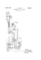
.In describing the invention in detail reference will be made to the accompanying drawing, in which the portion in the dotted rectangle represents the apparatus located in the interloc ing tower, and the remaining apparatus illustrated is located at a distant track switch on the railway system,
Structure Referring to the drawing, the track rails 1 of a railway system have been shown divided into blocks by insulating joints 2, to provide the usual track circuits, of which the 'detector track circuit having the track relay DR and a track battery 3 and the approach section having the track relay TR and a track battery l only have been shown. The siding or diverging route has been indicated by track rails 5 connected to the main track through the medium of the track switch S, which track switch is operated by-a switch machine SM. The switch machine SM is controlled by the snap action, .or stick type, relay CR, which relay after it is operated to one of its operated positions remains there until it is electrically or manually operated to the other position, even though it is deenergized in the mean time.
In the interlocking tower, conventionally shown by the dotted rectangle T, is located a lever L having pole changer contacts -11 and 12-14, of which the contacts 10 and 11 control the flow of current to the polar control relay CR, and of which the pole changer con-' S and the switch machine SM, whereby the relaylR will assume one polar position namely the full-line position when the switch S assumes the main track fully locked position and will assume the other polar position namely the dotted position when this track switch S assumes the take-siding locked-u condition.
Associated with the lever L in the tower T is also a' stick relay R, which relay can only be picked up when the lever L is in correspondence with the switch machine SM and with approach conditions manifested by the contact 20 of the track relay DR and the contact 21 of the track relay. TR are closed, and with the contacts 22 closed manifesting that all of the conflicting signals are at stop, and this stick relay SR when once picked up will only remain up so long as said contacts 20, 21 and 22 remain closed.
The tower apparatus also includes a lock relay LR which is normally deenergized and normally short circuits the control relay CR through the shunting wires 23 and 24. This lock relay LR can only be picked up when the stick relay SR is energized and the lever L is out of'correspondence with the distant traflic controlling device or switch machine SM .as'manifested through the indicating relay IR. There are also provide two indicating lamps for each of the levers L, the lamp 00C of which indicates when illumi nated that the lever L is out of correspondence with the distant traflic controlling device, and the lamplUL of which when illuminated indicates t at the lever is electrically unlocked .and may, u on being moved, control its associated tra c controlling device. 7
Even though the contacts 22, which are closed if the signals of conflicting routes are at stop and which have been shown included in the ick up and stick circuit for the stick relay SR, thus gareventing control of the switch machine M under conflicting route conditions, have been illustrated, it is to be understood that these contacts 22 may be omitted and suitable local interlocking between the signals and the switch machine may be employed, this local interlocking acting either upon the control relay CR or acting to prevent operation of the switch machine SM under dangerousconditions by suitable contacts included in the normal and the reverse circuits N and R of the switch machine SM. Also, in spite of the fact that I the invention has been shown applied to a .switch machine, it is to be understood that the 1' same principles underlying the present invention ma be applied to control circuits for control 'n derails, wayside semaphore or-light signals, mentioned the various elements of the system, it is deemed expedient to consider the operation of the system, this in order to more clearly point out t e operating characteristics and the features of safety vided by the system.
Operation and facility pro- Let us assume that the operator in the tower T wishes to operate the track switch S and the like. Having now to the take-siding position, and .in order.
to do so moves the lever L to the dotted posi-- ,tion at a time when the detector track circuit including the track relay DR and .the approach section including the track relay TR are unoccupied and the contacts 22 are closed manifesting that the signals of conflicting routes are at stop. Under the conditions assumed the stick relay SR is energized through the following. circuit :-beginning at the terminal rent, such as a atter front contact 20 of the track relay DR,w1re 30, front contact 21 of the track relay TR, wire. 31, contacts 22,
Picking up of the lock relay LR removes the shunting wires 23 and 24- from the line circuit leadingto the control relay CR and with the contacts 10 and 11 of the lever sumin their dotted position the control relay C isenergized. through the following circuit :beginning at the positive terminal of the battery 50, wires 47 and 48, contact 10 of the lever L, wire 49, front contact 51 of the lock relay LR, line wire 52, winding of the control relay CR, line wire 53, front contact 54 of the relay LR, wire 55, contact 11 of the lever L, wires 56 and 57, and back to the battery 50. Flow of current inthe circuit just traced operates the control relay OR to its left hand otted position, therebyop- Las- Y crating the switch machine SM to the take- 1 siding position througlhthe medium of its reverse circuit throu Y the reverse wire R andthe contact 58 o the control relay CR.
dti
till
As soon as the switch machine SM has been operated to the take-siding ositionthe contact 1617 within the switc machine, or in a suitable switch box, are operated to the dotted position, thereby reversin the polarity of current applied to the in icating relay IR and operating this rela IR to its dotted position, through the me ium of the line wires 59 and 60. With the indicatcontact 20 of the relay DR, wire 30, contact 21, wire 31, contacts 22, wires 32, and 41, contact 15 then assuming theiull line posi-. tion, wires 42 and 43, contact 12 of lever L assuming the dotted position, wire 59, indicating lamp U00, to the other terminal C of said source. "The unlocked lever lamp UL is of course illuminated so long as the contacts 20, 21 and 22 are closed, and the circuit for this lamp UL, readily traced in the drawings, and including the wire is otherwise intact. It is thus seen that with the lever L out of correspondence with the indicating relay ill and with the stick relay SR energized the lock relay LR is energized so long as this out of correspondence and safe route and approach locking condition exists, and that the lock relay LR is deenergized as soon as the indicating relay 1R gets into correspondence with the lever L.
Let us now see what the effect would be if the operator operated the lever L at a time when the unlocked lamp UL is dark as a result of the opening of one of the contacts 20, 21 or 2:2. Such opening of one of these con-' tacts 20, 21 or 22 will of course extinguish the lamp UL, advising the operator that he must not operate the lever, and will deenergize the stick relay SR. If the operator under this condition were to operate the lever, say from the normal to the dotted position, the lock relay LR would not be energized because the contact 45 of the stick relay SR is open. Furthermore, if the operator left the lever L in the dotted position and traffic or route conditions cleared up later, so that the contacts 20, 21 and 22 are then all closed, the unlocked lever lamp UL would be again illuminated, as would also the out of correspondence lamp OOC, but the stick relay. SR would remain deenergized, because the pickup circuit for this stick relay, and including the wire 61 and the contact 14 of the lever L would be incomplete, because the contact 14 of the lever L and the contact 15 of the relay 1B are out of correspondence, so that the multiple part of. this circuit including the wires 42 and 39 in multiple is open, and the Ty I stick relay SR cannot be picked up.
The illumination of the out of correspondence lamp 00G under the conditions assumed, would of course direct the attention .of the operator to the fact that his lever L is out of correspondence with the switch machine SM, in response to which the operator would return the lever L to its normal position under which condition the, stick relay SR would be picked up through the following its left hand full line position, wire 42,
contact 14 of the lever L, wires 61 and 36, winding of the stick relay SR, and to the other terminal C of the same battery. As soon as the stick relay. SR assumes its energized position the closure of its stick contact 3 1 shunts the'hontacts 14 and 15 and the as- DR, wire 30, front contact 21 of the sociated wires 39, 40, 41, 42 and 61, so. that the stick relay SR remains stuck'up through its stick circuit heretofore traced so long as traific and route conditions are favorable, from which it'is apparent that the switch machine SM may be operated in response to movement of the lever L back to the dotted position.
Although the lock relay LR has been shown slow acting, this relay may be rather quick acting, in that this relay is not deenergized until the operating function has been com pleted in its entirety. On the other hand, this relay LR is preferably slightly slow acting so' that it will not respond to an instantaneous or transient application of current thereto.
Having thus shown and described one pa 1'- ticular combination of circuits and devices for carrying out the underlying principles of the present invention, namely the provision of means including a lever for controlling a distant trafiic controlling device in too which the lever must be operated concurrently with safe traific approach locking and route conditions, and if the lever is operated under such safe conditions the control circuit for controlling the distant trafiic controlling device is again broken and the control circuit is short circuited to prevent interference due to the application of unauthorized current as soon as the distant traffic controlling device gets into correspondence with the lever, it is desired to be understood that the particular system illustrated has been selected for the purpose of disclosing the principles of the present invention and the advantages resulting therefrom, and has not been selected with additions may be made to adapt the invention to the particular problem encountered in racticing the same, all without departing rom the s irit or scope of the invention'or the idea means underlying the same,-except as demanded by the scope of the following claims. I
What I claim as new is 1. In an interlocking system for railroads;
. the combination with a distant tragic controlling device; of a free mechanica nonlockable lever for controlling such tra 0 controlling device but normally ineflfective to permit said trafiic controlling device being controlled by said lever; and other means for permitting control of said traffic controlling device by said lever which requires movement of said lever when trafiic conditions are proper comprising; a relay which must "be energized to permit control of said traflic controlllng device by said lever, and means for energlzing said relay efi'ective only if trafiic conditions are proper and said lever and said traflic controlling device are out of correspondence.
2. In an interlocking system for railroads;
' the combination with a distant traffic controlling device; of a free mechanically nonlockable lever for controlling such trafiic controlling device but normally inefiective to permit said traffic controlling device being controlled by said lever; and other means for ermitting control of said traific controlling device by said lever which requires .4 movement of said lever when traific and route conditions are proper comprising; a relay which must be energized to permit con trol of said traflic controlling device by said lever, and means for energizing said relay eifective only if trafiic and-route" conditions are proper and said lever and said traflic controlling device are out of correspondence.
3. In an interlocking system for railroads;
the combination with a distant trafiic controlling device; of a free mechanically .nonlockable lever for controlling such traific controlling device but normally 'ineflective to permit said traflic controlling device being controlled by said lever; and other means for permitting control of said traflic controlling device by said lever which requires movement of said lever when traific conditions are proper comprising; a release relay which must be energlzed to permit control of said traflic controlling deviceby'said lever, a stick relay which can only be picked up when trafiic and route conditions are favorable and when said lever and said traflic controlling device assume corresponding positions and which will remain stuck up rrespe'ctiv'e of whether said lever and trafiic controlling device assume corr ondin positions, and a circuit for said :Zliease re ay including a front contact of said stick relay.
4. In an interlocking s stem for railroads; the combination with a dlstant traflic controlling device; of a free mechanically non-lockable lever for controllin such traflic controlling device but normal y ineflective to permit said trafiic controlling device being controlled by said lever; and other means for permitting control of said traflic controlling device by said lever which requires movement of said lever whenftraflic conditions are proper comprising; a release relay which so must be ener ized to permit control of said trafiic contro lin device by said lever, a stick relay whic can only be picked up when traflic and route conditions are favorable and when said lever and said traflic con- 35 trolling device assume correspondingpositions and which will remain stuck up 1rrespective of whether said lever and trafiic controlling device assume corresponding positions, and a circuit for said release relay including a front contact. of said stick relay and contacts closed when said lever and said t raflic controlling device are out of correspondence.
5. In an interlocking system for railroads; the combination with a distant traflic controlling device; of a free mechanicall nonlockable lever for controlling such tra 0 controlling device but normally inefiective to permit said traflic controllin device being no controlled by said lever; an other means for permitting control of said trafiic controlling device by said lever which requires movement of said lever when traflic conditions are proper comprising; a relay which must be energized to permit control of said traflic controlling device by said lever, means for energizing said relay efiective only if trafiic conditions are proper and said lever and said traific controlling device are out of no correspondence, and means for indicating when traflic and route conditions are proper.
6. In an interlocking system for railroads; the combination with'a distant traflic controlling device; of a free mechanically nonlockable lever for controlling such trafiic controlling device but normally ineffective topermit said traflic controlling device being controlled by said lever; and other means for permitting control of said trafiic controlling device by said lever which requires movement of said lever when trafiic and route conditions are proper comprising; a relay which must be energized to permit control of said trafiic controlling device by said lever, means for energizing said relay efiective only if trailic and route conditions are proper and said lever and said traflic controlling device are out of correspondence, and means for in- 13 dicating when trafiic, and route conditions are proper. i
7., In an interlocking system for rallroads;
the combination with a distant traflic controlling device; of a free mechanicall nonlockable lever for controlling such tra controlling device but normally ineffective to permit said traflic controlling device being controlled by said lever; and other means for permitting control of said traiiic controlling device by said lever which requires movement of said lever when trafllc conditions are proper comprising; a release relay which must be energized to permit control of said trafic controlling device by said lever, a stick relay which can only be picked up when traffic and route conditions are favorable and when said lever and said traific controlling device assume corresponding positions and which will remain stuck up irrespective of whether said lever and trafiic controlling device assume corresponding positions, a circuit for said release relay including a front contact of said stick relay, and means for indicating when said lever and said traflic controlling device assume non-corresponding positions.
8'. ln an interlocking system for railroads; the combination with a distant trailic controlling device; of a free mechanically-nonlockable lever for controlling such trailic controlling device but normally ineffective to permit said traific controlling device being controlled by said lever; and other means tor permitting control ofsaid traflic controlling device by said lever which requires movernent of said lever when traific conditions are ill tilt
proper comprising; a release relay which must be energized to permit control of said trafiic controlling device by said lever, a stick relay which can only be picked up when trafiic and routeconditions are favorable and when said lever and said traific controlling device assume corresponding positions and which will remain stuck up irrespective of whether said lever and traffic controlling device assuming corresponding positions, a circuit for said release relay including a front contact of said stick relay and contacts closed when said lever and said traific controlling device are out of correspondence, and means for indicating when said lever and'said traffie controlling device assume non-corresponding positions.
9. In an interlocking system for railroads; the combination with a distant trafiic controlling device; of a free mechanically nonlockable lever for controlling such trafiic controlling device but normally inefi'ective to permit said trafiic controlling device being controlled by said lever; and other means for permitting control of said traific controlling device by said lever which requires movement of said lever when tr'ailic conditions are proper comprising; a release relay which must be ener zed to permit control of said traflic contro ling device by said lever, a stick rela which can only be picked u when traflic an route conditions are favora 1e and when said lever and said tra-fiic controllin device assume corresponding positions an which will remain stuck up. irrespective of whether said lever and traflic controlling device assume corresponding positions, a. circuit for said release relay including a front contact of said stick relay and contacts closed when said lever and said traflic controlling device are out of correspondence, and means for indicating when trailic and route. conditions are favorable,
10. In an interlocking system for railroads; the combination with a distant traflic controlling device; of a free mechanically non-lockable lever for controlling such trafiic controlling device but normally lneife'ctive to permit said traflio controlling device being controlled by said lever; and other means for. permitting control of said traffic controlling device by said lever which requires movement of said lever when traflic conditions are pro er comprising; a release relay which must e energized to permit control of said traflic controlling device by said lever, a stick relay which can only be picked up when traffic and route conditions are favorable and when said lever and said traflic controlling device assume corresponding positions and which will remain stuck up irrespective of whether said lever and traflic controlling device assume corresponding positions, a circuit for said release relay including a front contact of said stlck relay and contacts closed when said lever and said trafiic controlling device are outof correspondence, and two indicators one of which is rendered active when traific and route conditions are favorable and the other of which is rendered active when said lever and said traflic controlling device assume noncorresponding positions. 7
11. In a centralized traific controlling system for railroads, a track switch, a switch machine for operating said track switch, a switch control relay for governing'said switch machine, a control lever, a polarized control.
circuit connecting said switch control relay and said control lever, approach locking means associated with said track switch for preventing during actuation of said means upon the passage of a train the operation of said switch control relay by said control lever, and means requiring said control lever to be in correspondence with said track switch subsequent to the release of said approach looking means before said control lever can govern said switch control relay.
12. In a centralized traflic controlling system for railroads, a track switch, a control lever, operating means for operating said track switch when actuated by said control lever, locking means preventingactuation of said operating means during passage of a train over said track switch, and means requiring said control lever to be in correspondence with said track switch subsequent to the passage of a train before said ogerating means can again be actuated by sai control lever 13. In combination, a switch machine, a lever operated contact, a lock means for preventing operation of said switch machine, and a control circuit for said switch machine including said lever o erated contact, said control circuit being e ective to cause. operation of said switch machine only if said locking means is inactive at the time of closure of said lever operated contact.
14. In combination, a distant track switch, a local lever for controlling the operation of said track switch, a relay for manifesting traflic conditions, and means for preventing response of said track switch to aphange in the position of said lever when said relay 1s deenergized and also preventing response of said track switch to such change in the position of said lever upon reenerglzation of said relay unless said lever is for a time placed into correspondence with said track switch after such reenergization of said relay.
- 15. In combination, a distant tratfic controlling device, a local lever for controllingthe operation of said device, a relay for manifesting traflic conditions, and means ior preventing response of said device to a change in the position of said lever when said relay is deenergized and also preventing response of said device to such change in the position of said lever upon reenergization of said relay unless said lever is for a time placed into correspondence with said device after such reenergization of said relay. 16. In combination, a distant trafiic controlling device, electro-responsive means for operating said device, a lever for controlling said means, a relay for manifesting traflic conditions, and means for preventing response of said electro-responsive means to a said lever and said electro-responsive device,
- ditions, and means for preventing response of said electro-responsive means to a change in' the'position of said lever when said relay is deenergized and also reventin such response upon reenergization of sai relay unless said lever is for a time placed into COI'IQJ.
spondence with said device after such reenergization of said relay, and means for indicating the condition of energization of said relay.
19. In combination, a distant trafiic controlling device, operating said evice, a lever for controlling said means, a relay for manifesting trafiic conditions, means for preventing response-of said electro-responsive means to a change in the position of said lever when said relay is deenergized and also reventing such response upon reenergizatlon of said relay unless said lever is for a time placed into correspondence with said device after such reenergization of said relay, means for indicating when said lever and said electro-responsive device are out of corres ondence, and means for indicating the con ition of energization of said relay.
ectro-responsive means for ANDBEW LA GDON.
change in the position of said lever when said relay is deenergized and also preventing such response upon reenergization of'said relay unless said lever is for a time placed into correspondence with said device after such reenergization of said relay.
17. In combination, a distant trafiic conv trolling device, electro-responsive means for operating said device, a lever for controlling said means, a relay for manifesting trafiic conditions,means for preventing response of said electro-responsive meansto a change in the position of said lever when said relay is deenergized and also preventing such response upon reenergization of said relay unless said lever is for a time placed into correspondence with said device after such reenergization of said relav. and means for indicating when
Priority Applications (1)
| Application Number | Priority Date | Filing Date | Title |
|---|---|---|---|
| US467233A US1852421A (en) | 1930-07-11 | 1930-07-11 | Interlocking system for railroads |
Applications Claiming Priority (1)
| Application Number | Priority Date | Filing Date | Title |
|---|---|---|---|
| US467233A US1852421A (en) | 1930-07-11 | 1930-07-11 | Interlocking system for railroads |
Publications (1)
| Publication Number | Publication Date |
|---|---|
| US1852421A true US1852421A (en) | 1932-04-05 |
Family
ID=23854901
Family Applications (1)
| Application Number | Title | Priority Date | Filing Date |
|---|---|---|---|
| US467233A Expired - Lifetime US1852421A (en) | 1930-07-11 | 1930-07-11 | Interlocking system for railroads |
Country Status (1)
| Country | Link |
|---|---|
| US (1) | US1852421A (en) |
Cited By (1)
| Publication number | Priority date | Publication date | Assignee | Title |
|---|---|---|---|---|
| US2986629A (en) * | 1951-10-30 | 1961-05-30 | Westinghouse Air Brake Co | Stuck-brake signalling apparatus whereby stuck-brake condition produces a simulated fault in brake control circuit |
-
1930
- 1930-07-11 US US467233A patent/US1852421A/en not_active Expired - Lifetime
Cited By (1)
| Publication number | Priority date | Publication date | Assignee | Title |
|---|---|---|---|---|
| US2986629A (en) * | 1951-10-30 | 1961-05-30 | Westinghouse Air Brake Co | Stuck-brake signalling apparatus whereby stuck-brake condition produces a simulated fault in brake control circuit |
Similar Documents
| Publication | Publication Date | Title |
|---|---|---|
| US1852421A (en) | Interlocking system for railroads | |
| US2018765A (en) | Train dispatching system for railroads | |
| US1926789A (en) | Railway traffic controlling apparatus | |
| US2019467A (en) | Centralized traffic controlling system | |
| US3064126A (en) | Centralized traffic control system for railroads | |
| US2581108A (en) | Dragging equipment detector signaling system for railroads | |
| US1852550A (en) | Train dispatching system for railroads | |
| US2117691A (en) | Railway traffic controlling apparatus | |
| US2109153A (en) | Traffic direction controlling system for railroads | |
| US2313887A (en) | Railway traffic controlling apparatus | |
| US2073050A (en) | Train dispatching system for railroads | |
| US1824181A (en) | Interlocking system for railroads | |
| US1824127A (en) | Interlocking system for railroads | |
| US2102988A (en) | Railway traffic controlling apparatus | |
| US1822497A (en) | Railway traffic controlling apparatus | |
| US2217227A (en) | Interlocking system for railroads | |
| US2082437A (en) | Interlocking system for railroads | |
| US2312740A (en) | Railway traffic controlling apparatus | |
| US1852548A (en) | Interlocking system for railroads | |
| US1476866A (en) | Switch protection for block-signal systems | |
| US1822913A (en) | Remote control apparatus | |
| US1354254A (en) | System for governing railway traffic | |
| US2082741A (en) | Traffic control system for railroads | |
| US1797560A (en) | Railway-traffic-controlling apparatus | |
| US2768287A (en) | Railway track switch controlling apparatus |