US1852415A - Magnet - Google Patents
Magnet Download PDFInfo
- Publication number
- US1852415A US1852415A US281691A US28169128A US1852415A US 1852415 A US1852415 A US 1852415A US 281691 A US281691 A US 281691A US 28169128 A US28169128 A US 28169128A US 1852415 A US1852415 A US 1852415A
- Authority
- US
- United States
- Prior art keywords
- casing
- opening
- yoke
- magnet
- secured
- Prior art date
- Legal status (The legal status is an assumption and is not a legal conclusion. Google has not performed a legal analysis and makes no representation as to the accuracy of the status listed.)
- Expired - Lifetime
Links
- 238000004804 winding Methods 0.000 description 11
- XEEYBQQBJWHFJM-UHFFFAOYSA-N Iron Chemical compound [Fe] XEEYBQQBJWHFJM-UHFFFAOYSA-N 0.000 description 2
- 229910001209 Low-carbon steel Inorganic materials 0.000 description 2
- 241000239290 Araneae Species 0.000 description 1
- 230000005520 electrodynamics Effects 0.000 description 1
- 229910052742 iron Inorganic materials 0.000 description 1
- 238000003754 machining Methods 0.000 description 1
- 239000000696 magnetic material Substances 0.000 description 1
- 238000000034 method Methods 0.000 description 1
Images
Classifications
-
- H—ELECTRICITY
- H04—ELECTRIC COMMUNICATION TECHNIQUE
- H04R—LOUDSPEAKERS, MICROPHONES, GRAMOPHONE PICK-UPS OR LIKE ACOUSTIC ELECTROMECHANICAL TRANSDUCERS; DEAF-AID SETS; PUBLIC ADDRESS SYSTEMS
- H04R9/00—Transducers of moving-coil, moving-strip, or moving-wire type
- H04R9/02—Details
Definitions
- M invention relates to electromagnets and particularly to so-called iron clad magnets such as are used in sound reproducers of the electrodynamic or moving coil type.
- lt is an object cl my invention to provlde a magnet which may be produced cheaply in quantity.
- Another object of my invention is to provide a magnet having a minimum number of carts.
- 1 hltill another ob'ect ot my invention is to provide a magnet having an annularair gap .ol accurate eiae d configuratmn.
- the present invention prov/Ides a magnet for this purpose requiring many fewer parts than necessary in'past types, and as these parts may he termed in large part by punch press the labor costs are greatly reduced.
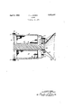
- the single figure of the drawing is an axial sectional view ot a magnet, embodying my invention, as applied to a sound reproducer.
- the magnet of my invention comprises a cup-shaped casing provided with an opening in the bottom.
- a winding surrounding a core which extends thru the opening in the bottom of the casing to form an annular air. gap.
- the core is secured to a yoke which seats agamst the to rim of the casing.
- the latter is preferably 1928. Serial No. 281,091.”
- a preferred form of my invention comprises a casing 6 which is preferably drawn. from mild steel plate.
- the casing is cup-shaped, and is provided with an end wall, formed integrally therewith and having a circular opening 7 formed centrally in said end wall. Near the end wall the casing is reduced in diameter toform a shoulder 9, and around the rim a flange 11 is provided.
- a bobbin or spool -12 rests against the shoulder, the spool carrying the magnet winding 13. Pins 14 pass thru the casing and engage the bobbin to hold it firmly against the shoulder.
- a circular plate or yoke 16 rests against the rim of the casing and is secured to the flange by the screws 17 which are threaded into the flange, passing thru holes 18 in the yoke. These holes are sufliciently large to permit an adjustment of the position of the yoke on the flange.
- a core 19 is secured to the yoke, and, passing thru the Winding, extends into the opening 7 to form an annular air gap.
- auxiliary plate 21 is secured to the integral end of the cup by the screws 22.
- This plate is also of magnetic material, such as mild steel. It increases the cross sedtion where the cup has been thinned by the drawing process, and gives a deeper air gap and provides the necessary ermeance for the lines of force converging rom the circumferonce toward the gap.
- the plate is a relative- 1 small and easily handled part, and it is, therefore, advantageous to securethe reproducer mechanism to it, the necessary machining operations being performed before it is at tached to the casing. It is obvious that if desired the plate may be placed inside instead of outside of the, casing, in which case the reproducer mechanism would attach to the casing itself.
- the moving element of the reproducer is the coil 23, mounted on the form 24 and positioned in the gap by the spider 26 so as to drive the conical diaphragm 27.
- the diaphragm is supported by a frame 28 which is secured to the plate 21 by the screws 29.
- the reproducer mechanism is in all essentials that described in my co-pending application, Serial No. 229,575, filed October 29, 1927, and need not be described here in further detail.
- An electromagnet comprising a cupshaped casing provided with an end formed integrally therewith and having an opening in said integrally formed end, a yoke adjustably secured to the rim of said casing, a core fixed to said yoke and extending-thru said opening to form an annular air gap, and a winding Within said casing and surrounding said core.
- An electromagnet comprising a cupdirectly shaped casing of substantially uniform thickness having a portion of reduced diameter forming a shoulder therein, and a winding within said casing supported by said shoulder.
- An electromagnet comprising a cupshaped casing having an opening in the bot tom thereof, a flange on the rim of said casing, a yoke adjustable on said flange, a core fixed to said yoke and extending thru said opening to form an annular air gap, and a winding within said casing and surrounding said core.
- a sound reproducer comprising a cupshaped casing provided with an end formed integrally therewith and having an opening therein, a winding in the casing, a core within the winding and extending thru the opening to form an annular air gap, a coil movably mounted in said air gap, a diaphragm driven by saida coil, an auxiliary plate secured to the en of the casing and having an opening registering with the opening in said end, and means mounted on said plate for supporting the coil and diaphragm.
- An electromagnet comprising a cupshaped casing of substantially uniform thickness having a portion of reduced diameter forming a shoulder therein and provided with an end formed integrally therewith and having an opening therein, a yoke secured to the rim of the casing, a core fixed to said yoke and extending through said opening to form an annular air gap, and a winding within 1,sgs2,415
- An electromagnet comprising a cu shaped casing of substantially uniform thick ness havingl a portion of reduced diameter forming a s oulder therein and provided with an end formed integrally therewith and having an o ning therein, a yoke secured to the rim of t e casing, a core fixed to said oke and extendin through said opening to orm an annular air gap, a winding within said casing around the core and seating upon said shoulder, an auxiliary plate secured to the end of the casing and having an opening registering with the opening in said end, and means upon said plate for mounting a coil and diaphragm.
Description
P. L. JENSEN April 5, 1932.
MAGNET Filed May 51, 1928 INVENTOQ PETER L. \Z'fi/YSEN BY M 50M H/J AT'I'OENEK reamed Apr. 5, 1932 UNITED STATES- PATENT orrlcs PETEB L. JENSEN, OI ALAKEDA, GALII'OBNIA, ASSIGNOB 'I'O KARL K. JENSEN, OF
' PIEDIONT, CALIFORNIA.
MAGNET Application filed Kay 31,
M invention relates to electromagnets and particularly to so-called iron clad magnets such as are used in sound reproducers of the electrodynamic or moving coil type.
lt is an object cl my invention to provlde a magnet which may be produced cheaply in quantity. Y
.hnother object of my invention is to provide a magnet having a minimum number of carts. 1 hltill another ob'ect ot my invention is to provide a magnet having an annularair gap .ol accurate eiae d configuratmn.
filly invention possesses other objects and M valuable features, some of which will be set :lorth in the following descriptlon of my mvention which is illustrated in the drawings.
:lorming part oi the specification. It is to be understood that l do not limit myself to the showing made by the said description and drawings, a l may adopt varying forms of my invention within the scope of the claims. illecent advances in sound reproducers and amplifiers have demonstrated the great technical advantages oi the movingcoil or electrndynamic reproducer over other types. Uornmercially, however, such reproduoers have sufllered -from their greater cost of manulacture, which has necessitated their being W sold at double or more than double the price o'l other types. The major item of cost in these reproducers is the magnet, which is necessarily large and heavy, and which must he ads with a high degree of accuracy. The present invention prov/Ides a magnet for this purpose requiring many fewer parts than necessary in'past types, and as these parts may he termed in large part by punch press the labor costs are greatly reduced. The single figure of the drawing is an axial sectional view ot a magnet, embodying my invention, as applied to a sound reproducer.
Broadly stated, the magnet of my invention comprises a cup-shaped casing provided with an opening in the bottom. Within the casing is a winding surrounding a core which extends thru the opening in the bottom of the casing to form an annular air. gap. The core is secured to a yoke which seats agamst the to rim of the casing. The latter is preferably 1928. Serial No. 281,091."
formed with a shoulder near the bottom against which the coil rests, and there are also preferably provided a flange on the rim of the casing against which the yoke seats, and an auxiliary plate on the bottom of the easing and having an opening inre ister with the casing opening. This provid es an adequate cross section at all parts of the magnetic circuit and prevents areas of saturation. The reproducer mechanism is secured to the bottom of the casing.
In detail, a preferred form of my invention comprisesa casing 6 which is preferably drawn. from mild steel plate. The casing is cup-shaped, and is provided with an end wall, formed integrally therewith and having a circular opening 7 formed centrally in said end wall. Near the end wall the casing is reduced in diameter toform a shoulder 9, and around the rim a flange 11 is provided.
Within the casing a bobbin or spool -12 rests against the shoulder, the spool carrying the magnet winding 13. Pins 14 pass thru the casing and engage the bobbin to hold it firmly against the shoulder.
A circular plate or yoke 16 rests against the rim of the casing and is secured to the flange by the screws 17 which are threaded into the flange, passing thru holes 18 in the yoke. These holes are sufliciently large to permit an adjustment of the position of the yoke on the flange. A core 19 is secured to the yoke, and, passing thru the Winding, extends into the opening 7 to form an annular air gap.
An auxiliary plate 21 is secured to the integral end of the cup by the screws 22. This plate is also of magnetic material, such as mild steel. It increases the cross sedtion where the cup has been thinned by the drawing process, and gives a deeper air gap and provides the necessary ermeance for the lines of force converging rom the circumferonce toward the gap. The plate is a relative- 1 small and easily handled part, and it is, therefore, advantageous to securethe reproducer mechanism to it, the necessary machining operations being performed before it is at tached to the casing. It is obvious that if desired the plate may be placed inside instead of outside of the, casing, in which case the reproducer mechanism would attach to the casing itself.
The moving element of the reproducer is the coil 23, mounted on the form 24 and positioned in the gap by the spider 26 so as to drive the conical diaphragm 27. The diaphragm is supported by a frame 28 which is secured to the plate 21 by the screws 29. The reproducer mechanism is in all essentials that described in my co-pending application, Serial No. 229,575, filed October 29, 1927, and need not be described here in further detail.
I claim:
1. An electromagnet comprising a cupshaped casing provided with an end formed integrally therewith and having an opening in said integrally formed end, a yoke adjustably secured to the rim of said casing, a core fixed to said yoke and extending-thru said opening to form an annular air gap, and a winding Within said casing and surrounding said core.
2. An electromagnet comprising a cupdirectly shaped casing of substantially uniform thickness having a portion of reduced diameter forming a shoulder therein, and a winding within said casing supported by said shoulder.
3. An electromagnet comprising a cupshaped casing having an opening in the bot tom thereof, a flange on the rim of said casing, a yoke adjustable on said flange, a core fixed to said yoke and extending thru said opening to form an annular air gap, and a winding within said casing and surrounding said core.
4. A sound reproducer comprising a cupshaped casing provided with an end formed integrally therewith and having an opening therein, a winding in the casing, a core within the winding and extending thru the opening to form an annular air gap, a coil movably mounted in said air gap, a diaphragm driven by saida coil, an auxiliary plate secured to the en of the casing and having an opening registering with the opening in said end, and means mounted on said plate for supporting the coil and diaphragm.
5. An electromagnet comprising a cupshaped casing of substantially uniform thickness having a portion of reduced diameter forming a shoulder therein and provided with an end formed integrally therewith and having an opening therein, a yoke secured to the rim of the casing, a core fixed to said yoke and extending through said opening to form an annular air gap, and a winding within 1,sgs2,415
extending through said opening to form an annular air gap, a winding within said casing around the core and seating upon said shoulder, and an auxiliary plate secured to the end of the casing and having an opening registering with the opening in said end.
7. An electromagnet comprising a cu shaped casing of substantially uniform thick ness havingl a portion of reduced diameter forming a s oulder therein and provided with an end formed integrally therewith and having an o ning therein, a yoke secured to the rim of t e casing, a core fixed to said oke and extendin through said opening to orm an annular air gap, a winding within said casing around the core and seating upon said shoulder, an auxiliary plate secured to the end of the casing and having an opening registering with the opening in said end, and means upon said plate for mounting a coil and diaphragm.
In testimony whereof, I have hereunto set my hand.
PETER L. JENSEN.
said casing around the core and seating upon
Priority Applications (1)
| Application Number | Priority Date | Filing Date | Title |
|---|---|---|---|
| US281691A US1852415A (en) | 1928-05-31 | 1928-05-31 | Magnet |
Applications Claiming Priority (1)
| Application Number | Priority Date | Filing Date | Title |
|---|---|---|---|
| US281691A US1852415A (en) | 1928-05-31 | 1928-05-31 | Magnet |
Publications (1)
| Publication Number | Publication Date |
|---|---|
| US1852415A true US1852415A (en) | 1932-04-05 |
Family
ID=23078373
Family Applications (1)
| Application Number | Title | Priority Date | Filing Date |
|---|---|---|---|
| US281691A Expired - Lifetime US1852415A (en) | 1928-05-31 | 1928-05-31 | Magnet |
Country Status (1)
| Country | Link |
|---|---|
| US (1) | US1852415A (en) |
Cited By (2)
| Publication number | Priority date | Publication date | Assignee | Title |
|---|---|---|---|---|
| US3462559A (en) * | 1964-08-03 | 1969-08-19 | Dallas Richard Wilder | Two-piece loudspeaker |
| US4234766A (en) * | 1979-02-05 | 1980-11-18 | Cacho Gibson C | Speaker assembly |
-
1928
- 1928-05-31 US US281691A patent/US1852415A/en not_active Expired - Lifetime
Cited By (2)
| Publication number | Priority date | Publication date | Assignee | Title |
|---|---|---|---|---|
| US3462559A (en) * | 1964-08-03 | 1969-08-19 | Dallas Richard Wilder | Two-piece loudspeaker |
| US4234766A (en) * | 1979-02-05 | 1980-11-18 | Cacho Gibson C | Speaker assembly |
Similar Documents
| Publication | Publication Date | Title |
|---|---|---|
| US6359997B2 (en) | Loudspeaker having radially magnetized magnetic ring | |
| US2537723A (en) | Electromagnetic transducer | |
| US3766334A (en) | Double voice coil loudspeaker | |
| US1886816A (en) | Magnetic sound reproducer | |
| US2078469A (en) | Loudspeaker | |
| US4860370A (en) | Magnetically suspended acoustical speaker | |
| US1852415A (en) | Magnet | |
| US2090025A (en) | Sound reproducing device | |
| US8682022B2 (en) | Loudspeaker | |
| US2197649A (en) | Loudspeaker and method of formation | |
| US3319201A (en) | Unitary field structure for magnetic loudspeaker | |
| US1991738A (en) | Acoustic device | |
| US1995080A (en) | Loud speaker | |
| USRE23856E (en) | Permanent magnet structure for | |
| US1955248A (en) | Magnetic movement | |
| US1897294A (en) | Loud speaker and like apparatus | |
| US2469773A (en) | Loud-speaker diaphragm support member | |
| US2490227A (en) | Electrodynamic loud-speaker | |
| US2216961A (en) | Sound translating apparatus | |
| US1932459A (en) | Loud speaker | |
| US2186576A (en) | Reproducer | |
| JP2001000043U (en) | Magnetic circuit for speaker | |
| US2047361A (en) | Electrodynamic loudspeaker | |
| US2532413A (en) | Magnet structure for loud-speakers | |
| GB231420A (en) | Improvements in sound-reproducing apparatus |