US1852408A - Subaquatic rock drilling device - Google Patents
Subaquatic rock drilling device Download PDFInfo
- Publication number
- US1852408A US1852408A US409958A US40995829A US1852408A US 1852408 A US1852408 A US 1852408A US 409958 A US409958 A US 409958A US 40995829 A US40995829 A US 40995829A US 1852408 A US1852408 A US 1852408A
- Authority
- US
- United States
- Prior art keywords
- piston
- rod
- drill
- subaquatic
- rock drilling
- Prior art date
- Legal status (The legal status is an assumption and is not a legal conclusion. Google has not performed a legal analysis and makes no representation as to the accuracy of the status listed.)
- Expired - Lifetime
Links
- 238000005553 drilling Methods 0.000 title description 13
- 239000011435 rock Substances 0.000 title description 8
- 238000005266 casting Methods 0.000 description 11
- 230000008878 coupling Effects 0.000 description 7
- 238000010168 coupling process Methods 0.000 description 7
- 238000005859 coupling reaction Methods 0.000 description 7
- 210000004907 gland Anatomy 0.000 description 3
- XLYOFNOQVPJJNP-UHFFFAOYSA-N water Substances O XLYOFNOQVPJJNP-UHFFFAOYSA-N 0.000 description 3
- 230000000694 effects Effects 0.000 description 2
- 239000002184 metal Substances 0.000 description 2
- 230000009471 action Effects 0.000 description 1
- 230000004075 alteration Effects 0.000 description 1
- 230000008859 change Effects 0.000 description 1
- 230000006835 compression Effects 0.000 description 1
- 238000007906 compression Methods 0.000 description 1
- 230000009699 differential effect Effects 0.000 description 1
- 238000006073 displacement reaction Methods 0.000 description 1
- 210000003414 extremity Anatomy 0.000 description 1
- 239000004519 grease Substances 0.000 description 1
- 210000003141 lower extremity Anatomy 0.000 description 1
- 230000002093 peripheral effect Effects 0.000 description 1
- 230000000717 retained effect Effects 0.000 description 1
- 230000000630 rising effect Effects 0.000 description 1
- 230000035939 shock Effects 0.000 description 1
- 239000000725 suspension Substances 0.000 description 1
- 239000003643 water by type Substances 0.000 description 1
- 238000004804 winding Methods 0.000 description 1
Images
Classifications
-
- E—FIXED CONSTRUCTIONS
- E21—EARTH OR ROCK DRILLING; MINING
- E21B—EARTH OR ROCK DRILLING; OBTAINING OIL, GAS, WATER, SOLUBLE OR MELTABLE MATERIALS OR A SLURRY OF MINERALS FROM WELLS
- E21B7/00—Special methods or apparatus for drilling
- E21B7/12—Underwater drilling
Definitions
- This invention relates to improvements in subaquatic rock drilling devices.
- One of its main objects is to eii'ect a comprehensive coordination of the apparatus involved where 5 by a more direct application of the tools is secured, resulting in considerable added efficiency over rock drilling operations as usually conducted.
- this plant is principally used 011 floating equipment such as scows and other like vessels, and often in tidal waters subjected to constant change of surface level as well as to sudden surface disturbance caused by passingvessels, both of which effects create difficulty in the handling and manoeuvring of the plant by creating alterations to the relative position of the drill head in respect to the working face of the rock under operation.
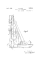
- Figure 1 is a general view in side elevation of the equipment as used by me for subaquatic rock drilling work.
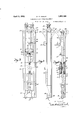
- Figure 2 shows to an enlarged scale the Serial No. 409,958.
- Figure 3 is a side View of Figure 2.
- Figure a is a se1ni-sectional view of Figure 3 with the cylinder head, bolts and springs removed.
- Figure 5 is a cross section on line 5-5 of Figure 2.
- Figure 6 is a cross section on line 6-6 of Figure 2.
- Figure 7 is an end view of Figure 2 from the front. 1
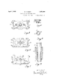
- Figure 8 is a cross section of the piston rod on line 88 in Figure 4 to an enlarged scale
- Figure 9 is a vertical section of the piston and drill rod coupling.
- Figure 10 is a cross section of the convex cylinder plug and bridge member.
- the numeral 10 indicates a scow adapted to support the drilling equipment and provided with an aperture 11 in its bottom through which the drill rod 12 passes.
- a vertical framework 13 suitably braced is supported from the bottom of the scow and provided with a peripheral watertight casing below the deck of same to maintain the buoyancy of the scow.
- a steam boiler 14 provides energy for operating winding drums 15 and pump 16.
- Asuitable sheave 17 is mounted on the head of the framework and supports the cable 18 terminating in the hook 19.
- a suitable shackle member 20 unites the hook 19 with the body-member 21 which incorporates the more salient features of the invention.
- the latter member comprises the steam cylinder 22, the water-box 23, the lower guide 24, and the suspension lugs 25 by which the whole of the drill rod equipment is supported.
- the steam cylinder 22 is provided with an ordinary D valve at 26 and is supplied with steam through the flexible pipe 27.
- a prominent feature of the device relates to means for absorbing the shock of the piston and parts moving therewith at the extremity of the return stroke.
- the piston and piston rod are integral and till the piston, after passing through the lower gland 36 of the cylinder 22, is continued through the water-box 23, its diameter being enlarged at 39 to permit of its being bored longitudinally as shown at 48, the bore 49 being continued from the coupling end of the piston rod to a point beyond the longitudinal centre line of-the water-box23.
- the piston rod 39 is pierced transversely by the apertures 40- Fig.-8). 7
- That portion of the piston rod 39 adjacent the apertures 40 is encircled by the water-box 23 so that water under pressure may be forced into the water-box and through the apertures 40 into the bore 49 of the piston rod '39 and thence into the hollow drill rod 12 to be delivered to the drill bit to free the cutting faces thereatof detritus regarding which it may be noted that in rapid high power drilling operations the effective removal of the detritus from the vicinity of the cutting ,head is a prominent determining factor in the efiicient operation of the plant.
- the top end of the steam cylinder is provided with a convex plug 28 having a substantial steam-tight metal to metal joint with the cylinder.
- This plugi28 is held in position by the bridge member 29 which is secured to the cylinder cover 30 at the opposite end of the cylinder by the longitudinal bolts 31 against the pressure of the helical compression springs 32, the heads 33- of the bolts 31 engaging rectangular recesses as shown whereby the cylinder head plug 28 may be relieved from receiving the full impact of the piston in the event of this latter being subjected to an undue strain, thus-absorbing and cushioning the impact by the action of the springs 32 should the piston be inadvertently driven beyond its intended stroke.
- the usual means for rotating the drill and piston rods . is indicated by the helically grooved rod .34 which engages a correspondinglygrooved nut secured to and positioned within an axial recess in the end of the piston, the top end of the rod 34 being secured to a ratchet wheel 35 in'connection with a pawl whereby the wheel35 and the rod 34 are held non-rotatable in one direction thereby rotating the piston and rods secured thereto according to the pitch of the said helical grooves as the rod 34 slides vertically through the grooved nut in the end of the piston.
- the gland 36 which is provided with a bushing divided diametrically for erection purposes is fitted with yoke extensions 37 which engage corresponding members on the cover 30 and serve to effectively reinforce thegland bolts 38.
- the water-box 23 is provided at each end with a tubular gland 41 and corresponding stufiingbox 42, and has a suitable water pipe connection at 43.
- the drill rod 12 used with this equipment may be of unusually greater length, provision being made in the framework to accommodate :this, whereby deeper drilling may be accomplished without thedelays consequent upon frequent shifts and replacements of tackle.
- the various sections of the drill rod are united "by sleeve couplings of the usual type.
- the water-box 23 is connected to the pump 16 by the flexible connection 50. j i
- the coupling which unites the ,piston rod .and the drill rod proper is developed as shown in detail in Figure 9 to meet the particular conditions of the case exemplified.
- the piston rod 39 isrprovided with a screwthread differing in pitch from that employed on the drill rod 12, and the direction of the pitch of both threads is in opposition to'that ofthe helical grooves in the rod 34, thereby tightening the screwhold of the coupling 44 which is further securedagainst concussional displacement by the differential effect between the two separate threads which sets up ,i
- a feature of the coupling 44 relatesto its complete enclosure of the screw threads on the-rods. "Eachend of the coupling is hellmouthed to a point which is beyondthe screw 4 thread on the rod, thus providing an annular receptacle for grease. 'By this device all possibility of damage to the non-engaged portion of the screw thread on the rods is eliminated and the engagement is retained in A a condition which facilitates dismantling.
- the lower extremity of the body member 21 carries the guide and bearing 24, the outer portion of which or cap 46 is secured to the body by the bolts 47. 7
- an elongated open rectangular casting having outer longitudinal slideways in its sides, a steam cylinder formed integrally with said casting and located between the sides thereof and adjacent one end, a drill-rod guide formed integrally with said casting adjacent its other end and located between the sides of said casting, and a water-box also formed integrally with said casting and lying intermediate the ends and between the sides thereof, a piston in said cylinder, a piston rod passing through said water-box and connected to said piston, and a drill rod passing through said drill-rod guide and connected to said piston rod.
Landscapes
- Life Sciences & Earth Sciences (AREA)
- Engineering & Computer Science (AREA)
- Geology (AREA)
- Mining & Mineral Resources (AREA)
- Physics & Mathematics (AREA)
- Environmental & Geological Engineering (AREA)
- Fluid Mechanics (AREA)
- General Life Sciences & Earth Sciences (AREA)
- Geochemistry & Mineralogy (AREA)
- Earth Drilling (AREA)
Description
D g NT SUBAQUATIC ROCK DRILLING DEVICE Filed Nov 26, 1929 3 Sheets-Sheet l W. D. GRANT April 5, 1932.
SUBAQUATIC ROCK DRILLING DEVICE iled Nov 26, 1929 3 Sheets-Sheet 2 f ver/ 11! Aprfl 5, 1932" 3 GRANT 1,852,408
SUBAQUATIC ROCK DRILLING DEVICE Filed Nov 26, 1929 5 Sheets-Sheet 3 Patented Apr. 5, 1932 UNITED STATES WILLIAM D. GRAN'JJQOF VANCOUVER, BRITISH COLUMBIA, CANADA SUBAQUATIC ROCK DRILLING DEVICE Application filed November 26, 1929.
This invention relates to improvements in subaquatic rock drilling devices. One of its main objects is to eii'ect a comprehensive coordination of the apparatus involved where 5 by a more direct application of the tools is secured, resulting in considerable added efficiency over rock drilling operations as usually conducted.
In this connection it is to be noted that this plant is principally used 011 floating equipment such as scows and other like vessels, and often in tidal waters subjected to constant change of surface level as well as to sudden surface disturbance caused by passingvessels, both of which effects create difficulty in the handling and manoeuvring of the plant by creating alterations to the relative position of the drill head in respect to the working face of the rock under operation.
To illustrate this point the operator may be drilling during a rising tide and this would necessitate the gradual paying out of cable in order to keep the drill effectively engaged otherwise the drill would be raised and its operation cease.
Conversely, should the drill be operated during a falling tide the supporting cable must be hauled in to compensate for the changing water level; in other words unless the operation is adroitly handled with great care and good judgment so that the blow from' the drill may be most effective and also that the proper end clearance of the piston within the steam cylinder may be maintained, there is grave danger of the piston being driven violently into the cylinder and smashing out the cylinder head.
In order to overcome these difliculties I have invented special means whereby the dangers recited are largely or entirely overcome.
The reasons for the attainment of these and other objects of the invention are better seen and more clearly described by the aid of the drawings accompanying and forming a part of this application, and in which:
Figure 1 is a general view in side elevation of the equipment as used by me for subaquatic rock drilling work.
Figure 2 shows to an enlarged scale the Serial No. 409,958.
body member of the device into which are incorporated the principal components of the plant under operation.
Figure 3 is a side View of Figure 2.
Figure a is a se1ni-sectional view of Figure 3 with the cylinder head, bolts and springs removed.
Figure 5 is a cross section on line 5-5 of Figure 2.
Figure 6 is a cross section on line 6-6 of Figure 2.
Figure 7 is an end view of Figure 2 from the front. 1
Figure 8 is a cross section of the piston rod on line 88 in Figure 4 to an enlarged scale,
Figure 9 is a vertical section of the piston and drill rod coupling.
Figure 10 is a cross section of the convex cylinder plug and bridge member.
In these drawings the numeral 10 indicates a scow adapted to support the drilling equipment and provided with an aperture 11 in its bottom through which the drill rod 12 passes. A vertical framework 13 suitably braced is supported from the bottom of the scow and provided with a peripheral watertight casing below the deck of same to maintain the buoyancy of the scow.
A steam boiler 14 provides energy for operating winding drums 15 and pump 16. Asuitable sheave 17 is mounted on the head of the framework and supports the cable 18 terminating in the hook 19. A suitable shackle member 20 unites the hook 19 with the body-member 21 which incorporates the more salient features of the invention.
The latter member comprises the steam cylinder 22, the water-box 23, the lower guide 24, and the suspension lugs 25 by which the whole of the drill rod equipment is supported.
The steam cylinder 22 is provided with an ordinary D valve at 26 and is supplied with steam through the flexible pipe 27. A prominent feature of the device relates to means for absorbing the shock of the piston and parts moving therewith at the extremity of the return stroke.
The piston and piston rod are integral and till the piston, after passing through the lower gland 36 of the cylinder 22, is continued through the water-box 23, its diameter being enlarged at 39 to permit of its being bored longitudinally as shown at 48, the bore 49 being continued from the coupling end of the piston rod to a point beyond the longitudinal centre line of-the water-box23. At an intermediate point within the water-box 23 the piston rod 39 is pierced transversely by the apertures 40- Fig.-8). 7
That portion of the piston rod 39 adjacent the apertures 40 is encircled by the water-box 23 so that water under pressure may be forced into the water-box and through the apertures 40 into the bore 49 of the piston rod '39 and thence into the hollow drill rod 12 to be delivered to the drill bit to free the cutting faces thereatof detritus regarding which it may be noted that in rapid high power drilling operations the effective removal of the detritus from the vicinity of the cutting ,head is a prominent determining factor in the efiicient operation of the plant.
It is to .be further noted that with this plant a high steam pressure is preferably employed on account of the great weight of the parts involved and the necessityvfor a maximum of compactness. Owing to the necessity for maintaining rapid and effective work, drills of comparatively large size are used involving corresponding increase in the strength and weight of all-the parts involved.
With these objects in view the top end of the steam cylinder is provided with a convex plug 28 having a substantial steam-tight metal to metal joint with the cylinder. This plugi28 is held in position by the bridge member 29 which is secured to the cylinder cover 30 at the opposite end of the cylinder by the longitudinal bolts 31 against the pressure of the helical compression springs 32, the heads 33- of the bolts 31 engaging rectangular recesses as shown whereby the cylinder head plug 28 may be relieved from receiving the full impact of the piston in the event of this latter being subjected to an undue strain, thus-absorbing and cushioning the impact by the action of the springs 32 should the piston be inadvertently driven beyond its intended stroke. 7
The usual means for rotating the drill and piston rods .is indicated by the helically grooved rod .34 which engages a correspondinglygrooved nut secured to and positioned within an axial recess in the end of the piston, the top end of the rod 34 being secured to a ratchet wheel 35 in'connection with a pawl whereby the wheel35 and the rod 34 are held non-rotatable in one direction thereby rotating the piston and rods secured thereto according to the pitch of the said helical grooves as the rod 34 slides vertically through the grooved nut in the end of the piston.
In order to withstand the effect of the severe vibrational and concussive strains the gland 36 which is provided with a bushing divided diametrically for erection purposes is fitted with yoke extensions 37 which engage corresponding members on the cover 30 and serve to effectively reinforce thegland bolts 38.
The water-box 23 is provided at each end with a tubular gland 41 and corresponding stufiingbox 42, and has a suitable water pipe connection at 43. The drill rod 12 used with this equipment may be of unusually greater length, provision being made in the framework to accommodate :this, whereby deeper drilling may be accomplished without thedelays consequent upon frequent shifts and replacements of tackle. The various sections of the drill rod are united "by sleeve couplings of the usual type. j The water-box 23 is connected to the pump 16 by the flexible connection 50. j i
The coupling which unites the ,piston rod .and the drill rod proper is developed as shown in detail in Figure 9 to meet the particular conditions of the case exemplified. The piston rod 39 isrprovided with a screwthread differing in pitch from that employed on the drill rod 12, and the direction of the pitch of both threads is in opposition to'that ofthe helical grooves in the rod 34, thereby tightening the screwhold of the coupling 44 which is further securedagainst concussional displacement by the differential effect between the two separate threads which sets up ,i
a self-locking function.
A feature of the coupling 44 relatesto its complete enclosure of the screw threads on the-rods. "Eachend of the coupling is hellmouthed to a point which is beyondthe screw 4 thread on the rod, thus providing an annular receptacle for grease. 'By this device all possibility of damage to the non-engaged portion of the screw thread on the rods is eliminated and the engagement is retained in A a condition which facilitates dismantling.
The lower extremity of the body member 21 carries the guide and bearing 24, the outer portion of which or cap 46 is secured to the body by the bolts 47. 7
From the above it will be seen that in consequence of incorporating the usually separated members 22, 23, 24 as an integral part of the massive casting forming the body member 21 much stability is added to the drilling operation so that the increased driving power and weight of the drill is not productive of undue vibration, but in consequence of the elongated guides is made available toincrease its drilling capacity.
Having now particularly described my inan elongated open rectangular casting having outer longitudinal slideways in its sides, a steam cylinder formed integrally with said casting and located between the sides thereof and adjacent one end, a drill-rod guide formed integrally with said casting adjacent its other end and located between the sides of said casting, and a Water-box also formed integrally with said casting and lying interinfediate the ends and between the sides there- 0 2. In subaquatic rock drilling apparatus, an elongated open rectangular casting having outer longitudinal slideways in its sides, a steam cylinder formed integrally with said casting and located between the sides thereof and adjacent one end, a drill-rod guide formed integrally with said casting adjacent its other end and located between the sides of said casting, and a water-box also formed integrally with said casting and lying intermediate the ends and between the sides thereof, a piston in said cylinder, a piston rod passing through said water-box and connected to said piston, and a drill rod passing through said drill-rod guide and connected to said piston rod.
In testimony whereof I aflix my signature.
WILLIAM D. GRANT.
Priority Applications (1)
| Application Number | Priority Date | Filing Date | Title |
|---|---|---|---|
| US409958A US1852408A (en) | 1929-11-26 | 1929-11-26 | Subaquatic rock drilling device |
Applications Claiming Priority (1)
| Application Number | Priority Date | Filing Date | Title |
|---|---|---|---|
| US409958A US1852408A (en) | 1929-11-26 | 1929-11-26 | Subaquatic rock drilling device |
Publications (1)
| Publication Number | Publication Date |
|---|---|
| US1852408A true US1852408A (en) | 1932-04-05 |
Family
ID=23622646
Family Applications (1)
| Application Number | Title | Priority Date | Filing Date |
|---|---|---|---|
| US409958A Expired - Lifetime US1852408A (en) | 1929-11-26 | 1929-11-26 | Subaquatic rock drilling device |
Country Status (1)
| Country | Link |
|---|---|
| US (1) | US1852408A (en) |
-
1929
- 1929-11-26 US US409958A patent/US1852408A/en not_active Expired - Lifetime
Similar Documents
| Publication | Publication Date | Title |
|---|---|---|
| US4176722A (en) | Marine riser system with dual purpose lift and heave compensator mechanism | |
| US7231981B2 (en) | Inline compensator for a floating drill rig | |
| US3714995A (en) | Motion compensating apparatus | |
| US2240519A (en) | Drill string shock absorber | |
| KR20130132379A (en) | A telescopic elevator bail, vessel comprising such the elevator bail and method of using the elevator bail | |
| CN109098675A (en) | A kind of deep compensation device of passive type deep-sea liter for ocean platform drilling well | |
| US1484065A (en) | Automatic depth-drilling machine | |
| NO321327B1 (en) | Floating offshore construction, as well as floating unit for the same | |
| US3703212A (en) | Method of rock drilling and apparatus for use therein | |
| US20070084606A1 (en) | Rig assist compensation system | |
| CN109505551A (en) | A kind of underground fishing type hydraulic booster release device | |
| CN105298390A (en) | Equipment for exploiting offshore oil | |
| US1852408A (en) | Subaquatic rock drilling device | |
| CN207582541U (en) | A kind of hydraulic bolt formula crane span structure locked instrument | |
| US1517556A (en) | Subaqueous drill | |
| CN106988671B (en) | A power rotary system integrated with a flushing and slag discharge system for a core drilling rig | |
| CN109025854A (en) | A kind of mounting structure of the mechanically driver type crown-block heave compensator directive wheel for ocean platform drilling well | |
| US1801788A (en) | Weight relief and fluid control on drill pipe | |
| CN113073950A (en) | Under-pressure overhaul operation machine and process method for oil well, water well and gas well | |
| US3621925A (en) | Well bailer | |
| CN212406586U (en) | Multi-branch yield tool pipe internal guiding tool | |
| CN214944041U (en) | Fixable support at front end of horizontal directional drilling machine | |
| US1910890A (en) | Hydraulic feed for rotary drills | |
| CN105090146A (en) | Hydraulic system for tensioning device of water-insulation guide pipe | |
| US1363586A (en) | Subaqueous rock-drill |