US1852400A - Blade lock for pocket knives - Google Patents
Blade lock for pocket knives Download PDFInfo
- Publication number
- US1852400A US1852400A US519850A US51985031A US1852400A US 1852400 A US1852400 A US 1852400A US 519850 A US519850 A US 519850A US 51985031 A US51985031 A US 51985031A US 1852400 A US1852400 A US 1852400A
- Authority
- US
- United States
- Prior art keywords
- blade
- handle
- spring
- tang
- edge wall
- Prior art date
- Legal status (The legal status is an assumption and is not a legal conclusion. Google has not performed a legal analysis and makes no representation as to the accuracy of the status listed.)
- Expired - Lifetime
Links
- 210000003811 finger Anatomy 0.000 description 3
- 210000003813 thumb Anatomy 0.000 description 3
- 239000002184 metal Substances 0.000 description 2
- 125000006850 spacer group Chemical group 0.000 description 2
- 208000036829 Device dislocation Diseases 0.000 description 1
- 238000010276 construction Methods 0.000 description 1
- 238000005520 cutting process Methods 0.000 description 1
- 238000004519 manufacturing process Methods 0.000 description 1
- 239000000463 material Substances 0.000 description 1
- 238000000034 method Methods 0.000 description 1
- 238000003825 pressing Methods 0.000 description 1
Images
Classifications
-
- B—PERFORMING OPERATIONS; TRANSPORTING
- B26—HAND CUTTING TOOLS; CUTTING; SEVERING
- B26B—HAND-HELD CUTTING TOOLS NOT OTHERWISE PROVIDED FOR
- B26B1/00—Hand knives with adjustable blade; Pocket knives
- B26B1/02—Hand knives with adjustable blade; Pocket knives with pivoted blade
- B26B1/06—Hand knives with adjustable blade; Pocket knives with pivoted blade with loosely-inserted spring
Definitions
- This invention relates to cutlery and more particularly to a pocket knife having means for securing its blade in either an opened or a closed position.
- One object of the invention is to provide a pocket knife with improved blade securing means which may be moved into or out of securing position and which when in an inoperative position will not interfere with w opening or closing of the blade in the usual manner but when moved to an operative position will firmly secure the blade in either its opened or close-d position.
- Another object of the invention is to provide a blade securing device which may be very easily moved to either an operative position by a thumb or finger of a hand holding the knife and will not be liable to be accidenl tally moved out of its adjusted position.
- Another object of the invention is to provide a Adevice of this character which is very simple in its construction and may be easily applied to a knife when manufacturing the same.
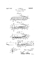
- Figure l is a side elevation of a knife constructed in accordance with this invention.
- Figure 2 is a longitudinal sectional view through the knife with the blade closed, and the securing device in an operative position
- Figure 3 is a view similar to Figure 2 showing the blade securing device moved to a l blade releasing position
- Figure 4 is a longitudinal sectional view through the knife with the blade opened and secured in the opened position
- Figure 5 is a sectional view taken transa versely through the knife along the line 5-5 to of Figure 2.
- the handle l of this knife is preferably formed from a metal plate bent to provide side walls 2 connected by a rear edge wall 3, thereby defining a. pocket 4 between the side walls which is open at one end and along the front of the handle. It will be understood that other methods may be followed when forming the handle, but it is important that a wall 3 or its equivalent be provided.
- a spacing block 5 is secured between the side 1931. Serial No. 519,850.
- this block may have a portion extending outwardly from between the side walls of the handle and perforated to form an eye 7 so that the knife may be attached to a chain or key ring if so desired.
- the blade 8 has its tang 9 engaged between the side Walls at the open end of the pocket and pivotally mounted by a pin l() so that the blade may be swung to a closed or an opened position, and in order to yieldably resist movement of the blade to an opened or closed position, there has been provided a spring ll which extends longitudinally in the handle with one end seated in arecess l2 formed in the spacer 5 and its free end bearing against the tang 9 as clearly shown in Figures 2 and 3. If so desired the spring may be formed as a part of the spacer as shown in Figure fl. This is the spring usually provided in order to yieldably resist movement of the blade and retain it in an opened or closed position.
- This strip is provided intermediate its ends with an extension or lug 11i projecting outwardly through an opening or slot 15 formed in the edge wall of the handle in spaced relation to the free end of the spring and the outer edge of the lug is roughened so that by placing a thumb or finger against this lug and applying pressure, the securing strip may be easily slid longitudinally until stopped by the lug contacting with an end wall of the slot.
- the strip 13 is tapered from the lug to its rear end so that it may be easily slid rearwardly between the spring and the la edge wall of the handle and the forward portion of the strip is reduced in spaced relation to the lug thereby forming in front of the lug a shoulder 16 and a tip 17 which tapers to the front end of the strip.
- the front end of the shoulder is curved as clearly shown in Figures 2, 3, and et so that when the fastener is thrust forwardly, the shoulder may easily move into place between the edge wall of the handle and the free end portion of the spring.
- this fastening device will serve very effectively to secure the blade in either an opened or a closed position when it is thrust forwardly as shown in Figures 2 and et, but by moving it rearwardly to the position shown in Figlure 3, the blade may be opened or closed in the usual manner.
- the fastener is so located that it may be moved to an operative position or an inoperative position by means of the thumb or a finger of the hand in which the knife is held and the blade grasped by the linger of the other hand and opened or closed. It will also be noted that when the fastener is in the operative position shown in Figures 2 and 4, it will be frictionally held in the set position by the pressure of the spring and it will not be liable to accidentally slip out of the operative position.
- a knife comprising a handle, a blade pivoted in the handle for swinging movement from a closed position within the handle to an opened position, a spring extending longitudinally in the handle and having a free'end engaging the tang of the blade to yieldably resist opening and closing of the blade, and a fastener slidable into and out of position to have wedging fit between the tang engaging end portion of the spring and a portion of the handle and secure the blade in opened and closed positions.
- a knife comprising a handle, a blade pivoted in the handle for swinging movement from a closed.positionxwithin the handle to an opened position, a spring extending longitudinally in the handle and having a free end overlapping the tang of the blade to yieldably resist opening and closing of the blade, and a fastener slidable longitudinally in the handle into and out of position to have wedging lit between the tang engaging end portion of the spring and a portion of the handle and secure the blade in opened and closed positions, the handle being formed Y with a1 slot and said fastener having an actuating element projecting outwardly through the slot wherebyl the fastener may be moved into and out of an operative position and be guided and limited in its sliding movement.
- a knife comprising aI handle having; side wallsfand an edge-walha blade'havinggits tang pivotally mountedbetween side wallsof the handle at the front end of the handleand spaced from the edge wall, aspringextending longitudinally in said'handle and'having a free end portion extending between theedge wall and tang Vof the blade and bearingagain'st the tang to yieldablfy7 resist -inovement of the blade to. opened and closed positions, and a fastener movable into and out of position fory wedging fit between theedge ywall .of the handle and free end portion of thespring to prevent opening and closing of the blade.
- a knife comprising a handle havingside walls and an edge wall, a blade having its tang pivotally mounted between side walls of the handle at the front end of the handle and spaced fromY the edge wall, a spring extending longitudinallyn in said handle and having a free end portion ext-ending between the edge wall and tang of the blade and bearing against the tangto yieldably resist movement of the blade to vopened and closed posi tions, and a fastener slidable longitudinally of the handle between. the spring and edge wall into andout Vof position to wedge the vfree end portion-of the spring tightly againstgthe tang of the bla-de and prevent opening and closing of the blade. 1 v
- a knife comprising a handle having side walls and an edge wall, a blade having its tang pivotally mounted between side walls of the'handle V'at the frontend of the handle and spaced from the edge wall., la spring extending longitudinally in said handle. and having afree end portion extending between the edge wall vand tang of the blade and. bearing against Vthe tangtoyieldably resist move- 6.
- a knife comprising a handle having side walls and an edge wall, a blade having its tang pivotally mounted between side walls of the handle at thefront end of the handle and l spaced from the edge wall, a spring extending longitudinally in said handle and having a free end portion extending between the edge wall and tang of the blade and bearing aga-inst the tang to yieldably resist movenient of the blade to opened and closed positions, and a fastener slidable longitudinally of the handle between the spring and edge wail into and out of position to wedge the free end portion of the spring tightly against the tang of the blade and prevent opening and closing of the blade, the edge wall being formed with a slot extending longitudinally therein, said fastener having an operating element projecting outwardly through the slot, and the front of the operating element being formed with a shoulder to have wedging fit between the edge wall of the handle and forward end of the spring when the fastener is thrust forwardly.
- T. il knife comprising a handle having side walls and an edge wall, a blade having its tang pivotally mounted between side walls of the handle at the front end of the handle and spaced from the edge wall, a spring extending longitudinally in said handle and having a free end portion extending between the edge wall and tang of the blade and bearing against the tang to yieldably resist movement of the blade to opened and closed positions, and a fasten-er slidable longitudinally of the handle between the spring and edge wall into and out of position to wedge the free end portion of the spring tightly against the tang of the blade and prevent opening and closing of the blade, the edge wall being formed with a slot extending longitndinally therein and said fastener having an operating element projecting outwardly through the slot, said fastener being tapered from the operating element to its rear end to facilitate movement of the fastener to a retracted position and the forward portion of the fastener being reduced in thickness in spaced relation to the operating element to forni a tapered prong engaged between the spring and the
Landscapes
- Life Sciences & Earth Sciences (AREA)
- Forests & Forestry (AREA)
- Engineering & Computer Science (AREA)
- Mechanical Engineering (AREA)
- Knives (AREA)
Description
April 5, 1932. T. CHAMPLIN BLADE LOCK FOR POCKET KNIVES F'i'led March 3, 1951 Patented Apr. 5, 1932 UNITED STATES TINT CHAMILIN, OF LITTLE VALLEY, NEW YORK BLADE LOCK FOR POCKET KNIVES Application filed March 3,
This invention relates to cutlery and more particularly to a pocket knife having means for securing its blade in either an opened or a closed position.
One object of the invention is to provide a pocket knife with improved blade securing means which may be moved into or out of securing position and which when in an inoperative position will not interfere with w opening or closing of the blade in the usual manner but when moved to an operative position will firmly secure the blade in either its opened or close-d position.
Another object of the invention is to provide a blade securing device which may be very easily moved to either an operative position by a thumb or finger of a hand holding the knife and will not be liable to be accidenl tally moved out of its adjusted position.
Another object of the invention is to provide a Adevice of this character which is very simple in its construction and may be easily applied to a knife when manufacturing the same.
The invention is illustrated in the accompanying drawings wherein:
Figure l is a side elevation of a knife constructed in accordance with this invention,
Figure 2 is a longitudinal sectional view through the knife with the blade closed, and the securing device in an operative position,
Figure 3 is a view similar to Figure 2 showing the blade securing device moved to a l blade releasing position,
l Figure 4 is a longitudinal sectional view through the knife with the blade opened and secured in the opened position, and
Figure 5 is a sectional view taken transa versely through the knife along the line 5-5 to of Figure 2.
The handle l of this knife is preferably formed from a metal plate bent to provide side walls 2 connected by a rear edge wall 3, thereby defining a. pocket 4 between the side walls which is open at one end and along the front of the handle. It will be understood that other methods may be followed when forming the handle, but it is important that a wall 3 or its equivalent be provided. A spacing block 5 is secured between the side 1931. Serial No. 519,850.
walls of the handle at one end thereof by a pin (i or in any other desired manner and this block may have a portion extending outwardly from between the side walls of the handle and perforated to form an eye 7 so that the knife may be attached to a chain or key ring if so desired. The blade 8 has its tang 9 engaged between the side Walls at the open end of the pocket and pivotally mounted by a pin l() so that the blade may be swung to a closed or an opened position, and in order to yieldably resist movement of the blade to an opened or closed position, there has been provided a spring ll which extends longitudinally in the handle with one end seated in arecess l2 formed in the spacer 5 and its free end bearing against the tang 9 as clearly shown in Figures 2 and 3. If so desired the spring may be formed as a part of the spacer as shown in Figure fl. This is the spring usually provided in order to yieldably resist movement of the blade and retain it in an opened or closed position. It has been found, however, that a knife merely equipped with such a spring is liable to cause a person to be cut either by the blade not being properly held in a closed position, or by being moved towards a closed position when cutting with the blade. This is specially true if it is attempted to force the blade longitudinally through tough material. In order to permit the blade to be firmly but releasably secured in either an opened or closed position this knife has been provided with a fastener 13 consisting of a metal strip which extends longitudinally between the spring 11 and the edge wall 3V of the handle.
This strip is provided intermediate its ends with an extension or lug 11i projecting outwardly through an opening or slot 15 formed in the edge wall of the handle in spaced relation to the free end of the spring and the outer edge of the lug is roughened so that by placing a thumb or finger against this lug and applying pressure, the securing strip may be easily slid longitudinally until stopped by the lug contacting with an end wall of the slot. The strip 13 is tapered from the lug to its rear end so that it may be easily slid rearwardly between the spring and the la edge wall of the handle and the forward portion of the strip is reduced in spaced relation to the lug thereby forming in front of the lug a shoulder 16 and a tip 17 which tapers to the front end of the strip. The front end of the shoulder is curved as clearly shown in Figures 2, 3, and et so that when the fastener is thrust forwardly, the shoulder may easily move into place between the edge wall of the handle and the free end portion of the spring.
By comparing F igure` 3 with either Figure 2 or Figure 4, it will be seen that when the fastener is in the releasing position shown in Figure 3, with the shoulder extending through the slot l5 thefree end portion of the spring will be permitted to have sufcient flexing movement to allow the blade to be moved, from a closed position to an opened position, or from an opened position to a closed position, whereas when the fastener is thrust forwardly to the position shown in Figures 2 and 4, and the shoulder is disposed between the edge wall of the handle and the spring, the fact that the shoulder is confined between the edge wall of the` handle and the spring, will cause a. wedging action to take place and the spring willbe prevented from n flexing in a direction to permit the blade to be moved to a closed position or to an opened position. It will thus be seen that this fastening device will serve very effectively to secure the blade in either an opened or a closed position when it is thrust forwardly as shown in Figures 2 and et, but by moving it rearwardly to the position shown in Figlure 3, the blade may be opened or closed in the usual manner. It will also be noted that the fastener is so located that it may be moved to an operative position or an inoperative position by means of the thumb or a finger of the hand in which the knife is held and the blade grasped by the linger of the other hand and opened or closed. It will also be noted that when the fastener is in the operative position shown in Figures 2 and 4, it will be frictionally held in the set position by the pressure of the spring and it will not be liable to accidentally slip out of the operative position.
What is claimed is:
l. A knife comprising a handle, a blade pivoted in the handle for swinging movement from a closed position within the handle to an opened position, a spring extending longitudinally in the handle and having a free'end engaging the tang of the blade to yieldably resist opening and closing of the blade, and a fastener slidable into and out of position to have wedging fit between the tang engaging end portion of the spring and a portion of the handle and secure the blade in opened and closed positions.
2. A knife comprising a handle, a blade pivoted in the handle for swinging movement from a closed.positionxwithin the handle to an opened position, a spring extending longitudinally in the handle and having a free end overlapping the tang of the blade to yieldably resist opening and closing of the blade, and a fastener slidable longitudinally in the handle into and out of position to have wedging lit between the tang engaging end portion of the spring and a portion of the handle and secure the blade in opened and closed positions, the handle being formed Y with a1 slot and said fastener having an actuating element projecting outwardly through the slot wherebyl the fastener may be moved into and out of an operative position and be guided and limited in its sliding movement.
3. .A knife comprising aI handle having; side wallsfand an edge-walha blade'havinggits tang pivotally mountedbetween side wallsof the handle at the front end of the handleand spaced from the edge wall, aspringextending longitudinally in said'handle and'having a free end portion extending between theedge wall and tang Vof the blade and bearingagain'st the tang to yieldablfy7 resist -inovement of the blade to. opened and closed positions, and a fastener movable into and out of position fory wedging fit between theedge ywall .of the handle and free end portion of thespring to prevent opening and closing of the blade.
Ll. A knife comprising a handle havingside walls and an edge wall, a blade having its tang pivotally mounted between side walls of the handle at the front end of the handle and spaced fromY the edge wall, a spring extending longitudinallyn in said handle and having a free end portion ext-ending between the edge wall and tang of the blade and bearing against the tangto yieldably resist movement of the blade to vopened and closed posi tions, and a fastener slidable longitudinally of the handle between. the spring and edge wall into andout Vof position to wedge the vfree end portion-of the spring tightly againstgthe tang of the bla-de and prevent opening and closing of the blade. 1 v
Y5. A knife comprising a handle having side walls and an edge wall, a blade having its tang pivotally mounted between side walls of the'handle V'at the frontend of the handle and spaced from the edge wall., la spring extending longitudinally in said handle. and having afree end portion extending between the edge wall vand tang of the blade and. bearing against Vthe tangtoyieldably resist move- 6. A knife comprising a handle having side walls and an edge wall, a blade having its tang pivotally mounted between side walls of the handle at thefront end of the handle and l spaced from the edge wall, a spring extending longitudinally in said handle and having a free end portion extending between the edge wall and tang of the blade and bearing aga-inst the tang to yieldably resist movenient of the blade to opened and closed positions, and a fastener slidable longitudinally of the handle between the spring and edge wail into and out of position to wedge the free end portion of the spring tightly against the tang of the blade and prevent opening and closing of the blade, the edge wall being formed with a slot extending longitudinally therein, said fastener having an operating element projecting outwardly through the slot, and the front of the operating element being formed with a shoulder to have wedging fit between the edge wall of the handle and forward end of the spring when the fastener is thrust forwardly.
T. il knife comprising a handle having side walls and an edge wall, a blade having its tang pivotally mounted between side walls of the handle at the front end of the handle and spaced from the edge wall, a spring extending longitudinally in said handle and having a free end portion extending between the edge wall and tang of the blade and bearing against the tang to yieldably resist movement of the blade to opened and closed positions, and a fasten-er slidable longitudinally of the handle between the spring and edge wall into and out of position to wedge the free end portion of the spring tightly against the tang of the blade and prevent opening and closing of the blade, the edge wall being formed with a slot extending longitndinally therein and said fastener having an operating element projecting outwardly through the slot, said fastener being tapered from the operating element to its rear end to facilitate movement of the fastener to a retracted position and the forward portion of the fastener being reduced in thickness in spaced relation to the operating element to forni a tapered prong engaged between the spring and the edge wall of the handle and a shoulder to have wedging fit between the edge wall and spring when the fastener is thrust forwardly and bind the spring firmly against the tang to prevent movement of the blade.
ln testimony whereof I aflix my signature.
TINT CHAMPLIN. [Ls]
Priority Applications (1)
| Application Number | Priority Date | Filing Date | Title |
|---|---|---|---|
| US519850A US1852400A (en) | 1931-03-03 | 1931-03-03 | Blade lock for pocket knives |
Applications Claiming Priority (1)
| Application Number | Priority Date | Filing Date | Title |
|---|---|---|---|
| US519850A US1852400A (en) | 1931-03-03 | 1931-03-03 | Blade lock for pocket knives |
Publications (1)
| Publication Number | Publication Date |
|---|---|
| US1852400A true US1852400A (en) | 1932-04-05 |
Family
ID=24070062
Family Applications (1)
| Application Number | Title | Priority Date | Filing Date |
|---|---|---|---|
| US519850A Expired - Lifetime US1852400A (en) | 1931-03-03 | 1931-03-03 | Blade lock for pocket knives |
Country Status (1)
| Country | Link |
|---|---|
| US (1) | US1852400A (en) |
Cited By (3)
| Publication number | Priority date | Publication date | Assignee | Title |
|---|---|---|---|---|
| US2728984A (en) * | 1952-09-13 | 1956-01-03 | Hopta Joseph | Tool element locking means for foldable tools |
| US4240201A (en) * | 1979-08-13 | 1980-12-23 | Mullin Steven W | Folding knife |
| US4837932A (en) * | 1985-08-06 | 1989-06-13 | Victorinox Ag | Locking blade pocket-knife |
-
1931
- 1931-03-03 US US519850A patent/US1852400A/en not_active Expired - Lifetime
Cited By (3)
| Publication number | Priority date | Publication date | Assignee | Title |
|---|---|---|---|---|
| US2728984A (en) * | 1952-09-13 | 1956-01-03 | Hopta Joseph | Tool element locking means for foldable tools |
| US4240201A (en) * | 1979-08-13 | 1980-12-23 | Mullin Steven W | Folding knife |
| US4837932A (en) * | 1985-08-06 | 1989-06-13 | Victorinox Ag | Locking blade pocket-knife |
Similar Documents
| Publication | Publication Date | Title |
|---|---|---|
| US1750139A (en) | Revolver holster | |
| US1701027A (en) | Fly-open knife | |
| US1362142A (en) | Pocket-knife | |
| US4124939A (en) | Folding knives | |
| US1584165A (en) | Knife | |
| US4837932A (en) | Locking blade pocket-knife | |
| US1454665A (en) | Knife lock | |
| US2575652A (en) | Pocket tweezer article | |
| US2134973A (en) | Knife | |
| US1614949A (en) | Folding hatchet | |
| US1994215A (en) | Pocket knife | |
| US1412373A (en) | Self-opening pocketknife | |
| US4173068A (en) | Bolster-actuated lockback knife | |
| US2008314A (en) | Spring closing device | |
| US2507019A (en) | Knife with reversible blade | |
| US1782901A (en) | Cutting device | |
| US1667462A (en) | Combination tool | |
| US4354313A (en) | Slide lock folding blade knife | |
| US2098678A (en) | Pocket knife | |
| US1898422A (en) | Fishing knife | |
| US3089239A (en) | Combination nail clipper implement | |
| US1852400A (en) | Blade lock for pocket knives | |
| US1451542A (en) | Combination utensil | |
| US400987A (en) | Arthur wilzin | |
| US1352108A (en) | Oyster-shucking knife |