US1852398A - Toaster - Google Patents
Toaster Download PDFInfo
- Publication number
- US1852398A US1852398A US429583A US42958330A US1852398A US 1852398 A US1852398 A US 1852398A US 429583 A US429583 A US 429583A US 42958330 A US42958330 A US 42958330A US 1852398 A US1852398 A US 1852398A
- Authority
- US
- United States
- Prior art keywords
- lever
- bread
- compartment
- toasting
- casing
- Prior art date
- Legal status (The legal status is an assumption and is not a legal conclusion. Google has not performed a legal analysis and makes no representation as to the accuracy of the status listed.)
- Expired - Lifetime
Links
Images


Classifications
-
- A—HUMAN NECESSITIES
- A47—FURNITURE; DOMESTIC ARTICLES OR APPLIANCES; COFFEE MILLS; SPICE MILLS; SUCTION CLEANERS IN GENERAL
- A47J—KITCHEN EQUIPMENT; COFFEE MILLS; SPICE MILLS; APPARATUS FOR MAKING BEVERAGES
- A47J37/00—Baking; Roasting; Grilling; Frying
- A47J37/06—Roasters; Grills; Sandwich grills
- A47J37/08—Bread-toasters
- A47J37/0814—Bread-toasters with automatic bread ejection or timing means
- A47J37/0821—Bread-toasters with automatic bread ejection or timing means with mechanical clockwork timers
Definitions
- This invention relates bread toasters, generally;
- An object of the invention is to provide a toaster including a toasting compartment having end, side and bottom walls adapted to receive and retain a slice of bread, said compartment having an opening at the top through which a slice of bread may be dropped by gravity to assume a toastlng position within the compartment, one of said walls being movable to permit the bread to be discharged by gravity from said compartment, and means automatically operable to actuate said movable wall after a predetermined toasting interval.
- a further object is to provide a toaster including a toasting compartment having end, side and bottom walls adapted to re ceive and retain a slice of bread, and a casing forming substantially a closed housing for said walls, said compartment and housing having an elongated opening at their tops through which a slice of bread may be dropped by gravity into said compartment to assume an upright toasting position, and one of said walls being movable, and a timing mechanism automatically operable to actuate said movable wall, after a predetermined time interval, to cause the bread to be discharged by ment.
- a further object is to provide a toaster including a toasting compartment provided with a movable bottom, and means for automatically causing the actuation of said bottom to eflect the release of the bread from the toaster, after a predetermined time interval.
- a further object is to provide a toaster including a casing having a toasting compartment therein adapted to receive and retain a slice of bread, and said compartment having a pivot-ed bottom provided with means for automatically operating it. after a predetermined length of time, whereby the bread, when toasted will be discharged from the bottom of the compartment.
- a further object is to provide a toaster comprising a casing having a toasting compartment therein provided with a hinged bottom, and a clock mechanism adapted to automatito improvements in gravity from said compartcally actuate said bottom whereby the bread will be discharged by gravity from said compalrtment, after a predetermined time interva I
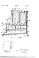
- Figure 1 is a vertical sectional view "on the line 11 of Figure 3, showing the movable bottom wall in breadsupporting position;
- Figure 2 is a view similar to Figure 1 showing the bottom after having been actuated to cause the bread to be discharged from the toasting compartment by gravity;
- Figure 3 is a vertical sectional view on the line 33 of Figure 1;
- Figure 4 is a sectional plan view on the line 4-4 of Figure 3;
- Figure 5 is a vertical sectional View on the line 55 of Figure 3, showing the means for retaining the movable bottom wall in bread-supporting position,-said parts being shown in operative positions;
- Figure 6 is a view similar to Figure 5, partially broken away, and showing the parts after having been actuated to release the bread; and 4
- Figure 7 is a detail sectional view on the line 77 of Figure 3, illustrating a means for varying the timing of the clock mechamsm.
- a toaster including a base member 2 having a casing mounted thereon, here shown comprising upright walls 3, 4, 5, and 6, and a top wall 7, suitably secured to the casing walls.
- a toasting compartment is provided within the casing or housing and is defined by inner end walls 8 and 9, and a plurality of small rods or wires 12 and 13, forming the side walls of the toasting compartment.
- An opening 14 is provided at the top of the toasting compartment throu h which a slice of bread may be dropped y gravity ifito said compartment.
- the upper portions of theinner end walls 8 and 9 are connected together by suitable tie members 10, and similar tie members 11 connect together the intermediate portions thereof.
- the tie members 10 and 11 cooperate to support the rods or wires 12 and 13, as shown in Figures 1 and 2.
- Mica plates 15 are shown secured to the tie members 10 and 11, and upon these mica plates suitable resistance wires 16 are mounted which form the heating elements for the toaster.
- the mica plates 15 are preferably provided with serrated edges to which the resistance wires 16 are suitably secured.
- Two mica plates are preferably arranged at each side of the toasting compartment in abutting relation, and the combined widths of each pair of said plates is such as to substantially span the distance between the inner end walls 8 and 9, as shown in Figure 3. It will thus be seen thatthe mica plates form, in efiect, auxiliary walls interposed between the outer casing walls 3 and 4, and the rods 12 and 13, forming the side walls of the toasting compartment.
- the heating elements16 are horizontally disposed on the inner surfaces of the mica plates, as indicated in dotted lines in Figure 3.
- An important feature of this invention resides in the means provided for supporting a slice of bread within the toasting compartment, and whereby the bread may be discharged by gravity from the lower portion of the holder, or through the bottom thereof,
- a plurality of spaced apart rods or wires 18 are secured to a rock shaft 19 having its terminals supported in suitable bearings provided in the walls 8 and 9,
- a small crank arm 21 is secured to one end of the rock .shaft and has a portion 22 bent outwardly to which one end of a tension spring 23 is connected, the opposite end of which is suitably secured to the wall 9.
- This spring constantly tends to rotate the shaft 19 in a direction to move the bottom 18 downwardly to bread-discharging position, as shown in full lines in Figure 2, to permit the bread to be discharged by gravity. from the toasting compartment through an opening 20, here shown rovided in the casing wall 4, as best shown in Figure 2.
- Means are provided for retaining the bot-,.
- tom wall 18 in operative or bread-supporting position as shown in full lines in Figure 1, and dotted lines in Figure 5 and, as here shown, consists of a. small detent 24 secured to the opposite end of the shaft 19 and adapted to be engaged by a lug 25 provided upon a lever 26 pivotally mounted upon the wall 8 by means of a pin 27.
- a spring 28 has one end secured to the portion 29 of the lever 26 and its opposite end to the wall 8 so as to normally hold the lever 26 in the position shown in Figures 1 and 5, against a suitable stop pin 31.
- the bottom wall 18 of the toasting compartment is provided with means for manually moving it from its inoperative position shown in Figure 2, to its operative position shown in Figure 1.
- a finger grip 36 is mounted upon one end of a rod 37, the opposite end of which is suitably secured to the shaft 19.
- the rod 37 is movable vertically in a slot 38 provided in the side wall 3 of the casing, and the finger grip 36 is situated so that it may be conveniently operated to return the bottom 18 to its operative position, as shown in Figure 1.
- Means are also provided for automatically releasing the bottom wall 18 after a predetermined toasting intervaL.
- a means is indicated in Figure 3, and comprises a suitable clock or timing mechanism 39, having a drive shaft 41 u on one end of which a pinion 42 is suitably secured.
- the pinioni42 meshes with a rack bar 43 having one end pivotally connected to an operating lever 44 pivoted at 45 to a fixed support such as the inner end wall 9.
- a flanged guide wheel 46 retains the rack bar 43 inconstant mesh with the pinion 42.
- the timing mechanism indicated in the drawin may be of the'spring provided in the casing wall 5 and is provided with a finger rip 47, whereby the lever may be convenient y depressed, each time a S1108 of bread is inserted into the toasting combe partment.
- the construction of the timing mechanism is such that each time the lever 44 is depressed, the mechanism will be rendered operative because of the reverse rotation imparted to the driving shaft 41, which rotation may cause a suitable drive spring, not shown, to be wound up.
- the timing mechanism will operate to slowly return the lever 44 to the dotted line position shown in Figure 3.
- the operating lever 44 is guided in its up and down movement by the walls of the slot 48 in the end wall 5, and is adapted to en age a projection 49 provided upon the re ease lever 26, as best shown in Figures 5 and 6.
- This projection is normally positioned in the path of the lever 44 so that just before the lever reaches the limit of its upward movement, it will engage the projection 49 and oscillate the release lever 26 and cause the detent 24 to become disengaged from the lug 25 provided upon the release lever 26, whereupon the rods 18, constituting the bottom wall of the toasting compartment, will immediately be moved downwardly from the position shown in Figure 1 to that shown in Figure 2, and cause the discharge of the bread from the toasting compartment.
- a stop mem ber 51 including a rod 52 having one end slidably supported in a bracket 53, preferably secured to the operating lever 44.
- a compression spring 54 is shown coiled about the rod 52 and has one end seated a ainst a washer 55 provided adjacent to the racket 53, and its opposite end against a similar washer 56 terminally mounted upon the. end of the rod 52 by means of an adjusting nut 57.
- the stop member 51 has a hub 58 adapted to be selecpluralityof notches tively received in one of a 59, provided in an edge of the slot 48 in which the operating lever 44 travels. The relative" position of the stop member 51 in the slot 48,
- stop mechanism herein disclosed may varied in numerous ways without depart ing from the scope of the invention.
- a toaster includin a casin having a toasting compartment t erein, a inged bottom for said compartment including a plurality of rods secured to a rock shaft in spaced relation, a detent secured to one end of said rock shaft, a lever pivoted within the casing and having a r0 ecti0n adapted to engage said detent and retain the bottom in operative position, a spring constantly urg; ing the frojection on said lever into the pat of said etent, and a portion of said lever projectin through an opening in said casing whereby said lever may be manually actuated to prematurel release said bottom.
- a toaster inc udin a casin having a toasting compartment t erein, a inged bottom for said compartment, a rock shaft supporting said bottom, a detent secured to one end of said rock shaft, a lever pivoted within the casing and having a. rojectionyadapted to engage said detent an retain the bottom in operative position, a s ring constantly urging the rojection on said lever into "the path of sai detent, an end portion of said ever projecting through casing whereby said lever may be manually actiiated to prematurely release said bottom, an matically release said bottom after a predetermined time interval.
- timing mechanism adapted to auto-' '95 an opening in said 1 int
Landscapes
- Engineering & Computer Science (AREA)
- Food Science & Technology (AREA)
- Electric Stoves And Ranges (AREA)
Description
M. BERSTED April 5, 1932.
TOASTER Filed Feb. 19, 1950 3 Sheets-Sheet 1 INVENTOR MAE TIN BERSTED aY & f
M M MM ATTOENEYS April 5, 1932. BERSTED 1,852,398
TOASTER Filed Feb. 19, 1930 M5 3 Sheets-Sheet Z 1 N {/15 N T01? M195? WW 55125720 P 1932- M. BERSTED 1,852,398
' TOASTER Filed Feb. 19, 1930 3 Sheets-Sheet 5 A 2/ 37M 44 22 I" I INVENT'OE 3 mm mv BEES r50 ar v F 10. 4 MM Patented Apr. 5, 1932 UNITED STATES PATENT OFFICE MARTIN BERSTED, 01 OAK PARK, ILLINOIS, ASSIGNOR T0 BERSTEIJ MANUFAG'IURIN G COMPANY, OF CHICAGO, ILLINOIS, A CORPORATION OF ILLINOIS 'roA'srEn Application filed February 19, 1930. Serial No. 429,583.
This invention relates bread toasters, generally;
An object of the invention is to provide a toaster including a toasting compartment having end, side and bottom walls adapted to receive and retain a slice of bread, said compartment having an opening at the top through which a slice of bread may be dropped by gravity to assume a toastlng position within the compartment, one of said walls being movable to permit the bread to be discharged by gravity from said compartment, and means automatically operable to actuate said movable wall after a predetermined toasting interval.
A further object is to provide a toaster including a toasting compartment having end, side and bottom walls adapted to re ceive and retain a slice of bread, and a casing forming substantially a closed housing for said walls, said compartment and housing having an elongated opening at their tops through which a slice of bread may be dropped by gravity into said compartment to assume an upright toasting position, and one of said walls being movable, and a timing mechanism automatically operable to actuate said movable wall, after a predetermined time interval, to cause the bread to be discharged by ment.
A further object is to provide a toaster including a toasting compartment provided with a movable bottom, and means for automatically causing the actuation of said bottom to eflect the release of the bread from the toaster, after a predetermined time interval.
A further object is to provide a toaster including a casing having a toasting compartment therein adapted to receive and retain a slice of bread, and said compartment having a pivot-ed bottom provided with means for automatically operating it. after a predetermined length of time, whereby the bread, when toasted will be discharged from the bottom of the compartment.
A further object is to provide a toaster comprising a casing having a toasting compartment therein provided with a hinged bottom, and a clock mechanism adapted to automatito improvements in gravity from said compartcally actuate said bottom whereby the bread will be discharged by gravity from said compalrtment, after a predetermined time interva I Other objects of the invention will appear from the following description and accompanying drawings and will be pointed out in the annexed claims.
In the accompanying drawings, there has been disclosed a structure designed to carry out the various objects of the invention, but it is to be understood that the invention is not confined to the exact features shown as various changes may be made within the scope of the claims which follow.
In the drawings:
Figure 1 is a vertical sectional view "on the line 11 of Figure 3, showing the movable bottom wall in breadsupporting position;
Figure 2 is a view similar to Figure 1 showing the bottom after having been actuated to cause the bread to be discharged from the toasting compartment by gravity;
Figure 3 is a vertical sectional view on the line 33 of Figure 1;
Figure 4 is a sectional plan view on the line 4-4 of Figure 3;
Figure 5 is a vertical sectional View on the line 55 of Figure 3, showing the means for retaining the movable bottom wall in bread-supporting position,-said parts being shown in operative positions;
Figure 6 is a view similar to Figure 5, partially broken away, and showing the parts after having been actuated to release the bread; and 4 Figure 7 is a detail sectional view on the line 77 of Figure 3, illustrating a means for varying the timing of the clock mechamsm.
In the selected embodiment of the invention here shown, there is illustrated, for purposes of disclosure, a toaster including a base member 2 having a casing mounted thereon, here shown comprising upright walls 3, 4, 5, and 6, and a top wall 7, suitably secured to the casing walls.
A toasting compartment is provided within the casing or housing and is defined by inner end walls 8 and 9, and a plurality of small rods or wires 12 and 13, forming the side walls of the toasting compartment. An opening 14 is provided at the top of the toasting compartment throu h which a slice of bread may be dropped y gravity ifito said compartment. The upper portions of theinner end walls 8 and 9 are connected together by suitable tie members 10, and similar tie members 11 connect together the intermediate portions thereof. The tie members 10 and 11 cooperate to support the rods or wires 12 and 13, as shown in Figures 1 and 2.
Mica plates 15 are shown secured to the tie members 10 and 11, and upon these mica plates suitable resistance wires 16 are mounted which form the heating elements for the toaster. -The mica plates 15 are preferably provided with serrated edges to which the resistance wires 16 are suitably secured. Two mica plates are preferably arranged at each side of the toasting compartment in abutting relation, and the combined widths of each pair of said plates is such as to substantially span the distance between the inner end walls 8 and 9, as shown in Figure 3. It will thus be seen thatthe mica plates form, in efiect, auxiliary walls interposed between the outer casing walls 3 and 4, and the rods 12 and 13, forming the side walls of the toasting compartment. The heating elements16 are horizontally disposed on the inner surfaces of the mica plates, as indicated in dotted lines in Figure 3.
An important feature of this invention resides in the means provided for supporting a slice of bread within the toasting compartment, and whereby the bread may be discharged by gravity from the lower portion of the holder, or through the bottom thereof,
when toasted. A plurality of spaced apart rods or wires 18 are secured to a rock shaft 19 having its terminals supported in suitable bearings provided in the walls 8 and 9,
as shown in Figure 4. These rods cooperate to provide a support for the bread and will hereinafter be referred to as the bottom wall of the toasting compartment. A small crank arm 21 is secured to one end of the rock .shaft and has a portion 22 bent outwardly to which one end of a tension spring 23 is connected, the opposite end of which is suitably secured to the wall 9. This spring constantly tends to rotate the shaft 19 in a direction to move the bottom 18 downwardly to bread-discharging position, as shown in full lines in Figure 2, to permit the bread to be discharged by gravity. from the toasting compartment through an opening 20, here shown rovided in the casing wall 4, as best shown in Figure 2.
Means are provided for retaining the bot-,.
The bottom wall 18 of the toasting compartment is provided with means for manually moving it from its inoperative position shown in Figure 2, to its operative position shown in Figure 1. To thus actuate the bottom, a finger grip 36 is mounted upon one end of a rod 37, the opposite end of which is suitably secured to the shaft 19. The rod 37 is movable vertically in a slot 38 provided in the side wall 3 of the casing, and the finger grip 36 is situated so that it may be conveniently operated to return the bottom 18 to its operative position, as shown in Figure 1. When the finger grip 36 is depressed, the detent 24 secured to the shaft 19, will be moved into the path of the lug 25 provided upon the lever 26, so that when the operator removes his finger from the grip 36, the detent 24 will engage the lug 25 and retain the bottom 18 in its operative position, shown in Figures 1 an 5.
Means are also provided for automatically releasing the bottom wall 18 after a predetermined toasting intervaL. Such a means is indicated in Figure 3, and comprises a suitable clock or timing mechanism 39, having a drive shaft 41 u on one end of which a pinion 42 is suitably secured. The pinioni42 meshes with a rack bar 43 having one end pivotally connected to an operating lever 44 pivoted at 45 to a fixed support such as the inner end wall 9. A flanged guide wheel 46 retains the rack bar 43 inconstant mesh with the pinion 42. The timing mechanism indicated in the drawin may be of the'spring provided in the casing wall 5 and is provided with a finger rip 47, whereby the lever may be convenient y depressed, each time a S1108 of bread is inserted into the toasting combe partment. The construction of the timing mechanism is such that each time the lever 44 is depressed, the mechanism will be rendered operative because of the reverse rotation imparted to the driving shaft 41, which rotation may cause a suitable drive spring, not shown, to be wound up. When the'operator removes his finger from the grip 47, the timing mechanism will operate to slowly return the lever 44 to the dotted line position shown in Figure 3.
The operating lever 44 is guided in its up and down movement by the walls of the slot 48 in the end wall 5, and is adapted to en age a projection 49 provided upon the re ease lever 26, as best shown in Figures 5 and 6. This projection is normally positioned in the path of the lever 44 so that just before the lever reaches the limit of its upward movement, it will engage the projection 49 and oscillate the release lever 26 and cause the detent 24 to become disengaged from the lug 25 provided upon the release lever 26, whereupon the rods 18, constituting the bottom wall of the toasting compartment, will immediately be moved downwardly from the position shown in Figure 1 to that shown in Figure 2, and cause the discharge of the bread from the toasting compartment.
To vary the length of the toasting period, there is shown in Figures 3 and 7, a stop mem ber 51 including a rod 52 having one end slidably supported in a bracket 53, preferably secured to the operating lever 44. A compression spring 54 is shown coiled about the rod 52 and has one end seated a ainst a washer 55 provided adjacent to the racket 53, and its opposite end against a similar washer 56 terminally mounted upon the. end of the rod 52 by means of an adjusting nut 57. The stop member 51 has a hub 58 adapted to be selecpluralityof notches tively received in one of a 59, provided in an edge of the slot 48 in which the operating lever 44 travels. The relative" position of the stop member 51 in the slot 48,
limits the downward movement of the oper-- ating lever 44, and therefore controls the timing of the clock mechanism. This will read ily be understood when it is known that the timing mechanism is adapted to operate at one speed only, regardless of the operative position in which the lever 44 may be in. It therefore follows that if the stop member 51 were positioned in one of the lower notches 59, it would takelonger for the lever 44- to return to its normal position, than it would if the stop member 57 were positioned in one of the upper notches 59, it being understood that the operating lever 44 returns to its normal starting position, indicated in dotted lines in Figure 3, at the conclusion of each toasting operation.
The stop mechanism herein disclosed may varied in numerous ways without depart ing from the scope of the invention.
claim as my invention:
1. A toaster includin a casin having a toasting compartment t erein, a inged bottom for said compartment including a plurality of rods secured to a rock shaft in spaced relation, a detent secured to one end of said rock shaft,a lever pivoted within the casing and having a r0 ecti0n adapted to engage said detent and retain the bottom in operative position, a spring constantly urg; ing the frojection on said lever into the pat of said etent, and a portion of said lever projectin through an opening in said casing whereby said lever may be manually actuated to prematurel release said bottom.
2. A toaster inc udin a casin having a toasting compartment t erein, a inged bottom for said compartment, a rock shaft supporting said bottom, a detent secured to one end of said rock shaft, a lever pivoted within the casing and having a. rojectionyadapted to engage said detent an retain the bottom in operative position, a s ring constantly urging the rojection on said lever into "the path of sai detent, an end portion of said ever projecting through casing whereby said lever may be manually actiiated to prematurely release said bottom, an matically release said bottom after a predetermined time interval.-
In witness whereof I have hereunto set my hand this 11th day of Februar 1930.
MARTIN ERSTED.
a timing mechanism adapted to auto-' '95 an opening in said 1 int
Priority Applications (1)
| Application Number | Priority Date | Filing Date | Title |
|---|---|---|---|
| US429583A US1852398A (en) | 1930-02-19 | 1930-02-19 | Toaster |
Applications Claiming Priority (1)
| Application Number | Priority Date | Filing Date | Title |
|---|---|---|---|
| US429583A US1852398A (en) | 1930-02-19 | 1930-02-19 | Toaster |
Publications (1)
| Publication Number | Publication Date |
|---|---|
| US1852398A true US1852398A (en) | 1932-04-05 |
Family
ID=23703850
Family Applications (1)
| Application Number | Title | Priority Date | Filing Date |
|---|---|---|---|
| US429583A Expired - Lifetime US1852398A (en) | 1930-02-19 | 1930-02-19 | Toaster |
Country Status (1)
| Country | Link |
|---|---|
| US (1) | US1852398A (en) |
Cited By (9)
| Publication number | Priority date | Publication date | Assignee | Title |
|---|---|---|---|---|
| US2444510A (en) * | 1944-10-05 | 1948-07-06 | Isserstedt Siegfried Gordon | Toaster |
| US2466085A (en) * | 1947-01-07 | 1949-04-05 | Dowrelio Angelo | Hot top tray |
| US2542406A (en) * | 1946-04-12 | 1951-02-20 | Flajole William | Electric toaster |
| US2548958A (en) * | 1947-08-12 | 1951-04-17 | Stephen P Dirosa | Toaster |
| US2552135A (en) * | 1948-04-10 | 1951-05-08 | Bertino Fred | Pop-down toaster |
| US2588100A (en) * | 1948-01-28 | 1952-03-04 | Dominic J J Federico | Automatic electric toaster |
| US4454803A (en) * | 1982-07-22 | 1984-06-19 | Alco Foodservice Equipment Company | Toaster |
| US4503758A (en) * | 1982-07-22 | 1985-03-12 | Alco Foodservice Equipment Company | Toaster |
| US4577550A (en) * | 1984-12-24 | 1986-03-25 | Hickory Industries, Inc. | Toaster |
-
1930
- 1930-02-19 US US429583A patent/US1852398A/en not_active Expired - Lifetime
Cited By (9)
| Publication number | Priority date | Publication date | Assignee | Title |
|---|---|---|---|---|
| US2444510A (en) * | 1944-10-05 | 1948-07-06 | Isserstedt Siegfried Gordon | Toaster |
| US2542406A (en) * | 1946-04-12 | 1951-02-20 | Flajole William | Electric toaster |
| US2466085A (en) * | 1947-01-07 | 1949-04-05 | Dowrelio Angelo | Hot top tray |
| US2548958A (en) * | 1947-08-12 | 1951-04-17 | Stephen P Dirosa | Toaster |
| US2588100A (en) * | 1948-01-28 | 1952-03-04 | Dominic J J Federico | Automatic electric toaster |
| US2552135A (en) * | 1948-04-10 | 1951-05-08 | Bertino Fred | Pop-down toaster |
| US4454803A (en) * | 1982-07-22 | 1984-06-19 | Alco Foodservice Equipment Company | Toaster |
| US4503758A (en) * | 1982-07-22 | 1985-03-12 | Alco Foodservice Equipment Company | Toaster |
| US4577550A (en) * | 1984-12-24 | 1986-03-25 | Hickory Industries, Inc. | Toaster |
Similar Documents
| Publication | Publication Date | Title |
|---|---|---|
| US1852398A (en) | Toaster | |
| US2878748A (en) | Bread toaster | |
| US1529342A (en) | Automatic electric toaster | |
| US1931345A (en) | Timed electric toaster | |
| US2319997A (en) | Shock absorber | |
| US2734448A (en) | mccullough | |
| US2307347A (en) | Automatic bread toaster | |
| US1697914A (en) | Family bread toaster | |
| US1888992A (en) | Electric toaster | |
| US1939247A (en) | Automatic toaster | |
| US1836538A (en) | Electric toaster | |
| US1843161A (en) | Dispensing, severing, and moistening apparatus | |
| USRE22781E (en) | Automatic bread toasting apparatus | |
| US2555697A (en) | Bread toaster | |
| US1921173A (en) | Automatic ejecting mechanism | |
| US2070333A (en) | Toaster | |
| US2223486A (en) | Toaster | |
| US1513248A (en) | Bread-dispensing device | |
| US2001362A (en) | Toaster | |
| US4142459A (en) | Toaster for step-by-step toasting | |
| US2687078A (en) | Automatic electric toaster with motor driven carriage and timer | |
| US2863377A (en) | Raising of bread carrier | |
| US2207947A (en) | Timer structure | |
| US1328192A (en) | Exhibiting device | |
| US1949124A (en) | Toaster |