US1852397A - Cutting device for cigarette strand machines - Google Patents
Cutting device for cigarette strand machines Download PDFInfo
- Publication number
- US1852397A US1852397A US29807828A US1852397A US 1852397 A US1852397 A US 1852397A US 29807828 A US29807828 A US 29807828A US 1852397 A US1852397 A US 1852397A
- Authority
- US
- United States
- Prior art keywords
- knife
- grinding
- disk
- cutting device
- strand
- Prior art date
- Legal status (The legal status is an assumption and is not a legal conclusion. Google has not performed a legal analysis and makes no representation as to the accuracy of the status listed.)
- Expired - Lifetime
Links
- 238000005520 cutting process Methods 0.000 title description 30
- 235000019504 cigarettes Nutrition 0.000 title description 14
- 230000033001 locomotion Effects 0.000 description 13
- 230000005540 biological transmission Effects 0.000 description 7
- 230000004048 modification Effects 0.000 description 7
- 238000012986 modification Methods 0.000 description 7
- 239000000463 material Substances 0.000 description 4
- 238000010276 construction Methods 0.000 description 1
- 230000001419 dependent effect Effects 0.000 description 1
- 230000000694 effects Effects 0.000 description 1
- 210000003746 feather Anatomy 0.000 description 1
- ZEKANFGSDXODPD-UHFFFAOYSA-N glyphosate-isopropylammonium Chemical compound CC(C)N.OC(=O)CNCP(O)(O)=O ZEKANFGSDXODPD-UHFFFAOYSA-N 0.000 description 1
- 239000002184 metal Substances 0.000 description 1
- 230000035515 penetration Effects 0.000 description 1
- 230000001105 regulatory effect Effects 0.000 description 1
Images
Classifications
-
- A—HUMAN NECESSITIES
- A24—TOBACCO; CIGARS; CIGARETTES; SIMULATED SMOKING DEVICES; SMOKERS' REQUISITES
- A24C—MACHINES FOR MAKING CIGARS OR CIGARETTES
- A24C5/00—Making cigarettes; Making tipping materials for, or attaching filters or mouthpieces to, cigars or cigarettes
- A24C5/14—Machines of the continuous-rod type
- A24C5/28—Cutting-off the tobacco rod
-
- Y—GENERAL TAGGING OF NEW TECHNOLOGICAL DEVELOPMENTS; GENERAL TAGGING OF CROSS-SECTIONAL TECHNOLOGIES SPANNING OVER SEVERAL SECTIONS OF THE IPC; TECHNICAL SUBJECTS COVERED BY FORMER USPC CROSS-REFERENCE ART COLLECTIONS [XRACs] AND DIGESTS
- Y10—TECHNICAL SUBJECTS COVERED BY FORMER USPC
- Y10T—TECHNICAL SUBJECTS COVERED BY FORMER US CLASSIFICATION
- Y10T83/00—Cutting
- Y10T83/303—With tool sharpener or smoother
Definitions
- the individual cigarettes are severed off the continually moved cigarette strand, as a rule, by means of a continually rotating cutting knife of circular or sickle-like shape supported usually in a reciprocating bearing member carried by the frame and being so controlled that it penetrates into the cigarette strand and cuts it through while the strand is being moved forwards by the means provided therefor.
- the knife is circular, its penetration into the strand is brought about generally in this way that it is supported eccentrically in its rotating bearing member so that the kn fe aide, irrespective of its rotation around its own axis, moves also on a circular path around the axis of said knife bearing member.
- care must be taken that the knife while rotating contacts with a suitable grinding tool and is re-ground by the same.
- the object of the present invention to arrange the grinding or re-grinding tooi in such a manner or, in other words, to regulate the movement of the knife relatively to the grinding tool in such a manner, that the cutting edge of the knife is re-ground effectively and unobjectionably while the strand cutting device is in operation, It is of no consequence whether the axial movement of the cutting edge in the direction of the strand is effected by an axial reciprocation of the knife axle or of the knife axle bearing member, or by a tumbling movement of this member, or by a screw-like arrangement of the knife at the circumference of said bearing member, or in any other suitable way.
- the ratio of transmission can be chosen 12:13, or 12:25, or 12 37, and so on, so that at every rotation of the knife carrier the knife itself performs one revolution, or two or more revolutions, plus 30, in consequence whereof always other parts of the knife will be ground.
- the knife is driven independently of the rotation of its carrier, for instance by a belt or a cord, its number of revolutions is, according to this invention, so chosen that it is very high in proportion to the number of rotations of the knife carrier so that during a comparatively small angle of rotation through which said carrier passes while it contacts with the grinding disk, the knife has made already one complete revolution and has been ground along its entire circumference.
- the accurate proportion between the number of revolutions of the knife carrier and the knife itself depends upon the circumstances of the individual case, for instance upon the shape of the grinding disk and upon the degree of accuracy demanded. It can be assumed that a contact between the knife and its carrier can be maintained while this latter moves through an angle of about 30.
- the pressure between the knife and the grinding disk is permitted to vary within wide limits that number of degrees can be surpassed, but if the accuracy required is to be very great, it is advisable to remain below that limit.
- the knife must then so rotate that it performs a complete revolution during that time in which the knife carrier moves through an arc of 30, or less or more, as the case may be. Thus, it will be necessary that in the normal case stated in which the carrier is in contact with the grinding tool while moving through an are or angle of 30, the knife rotates with twelve times the speed of the knife carrier.
- Another construction form of the present improved grinding device affords the possibilit of renderin the 'rin'din )rocedure at b D D the eccentrically supported circular knife particularly simple, in that the grinding tool is arranged concentrically with respect to the rotating knife carrier in such a manner that either it is in constant contact with the knife or is made to contact with it only during certain predeterinined periods of time.
- the grinding tool can be moved axially with respect to the cutting knife by means of suitable control members, or it can be composed of segments in" such a manner that there is between each two active, i. e. grinding, segments a segment consisting of a non-grinding material.
- the grinding means need not be moved axially with respect to the cutting knife, and in spite thereof burning of the knife and smearing of the grinding disk will be prevented. It is, of course, possible to give the grinding disk also in this case an additional movement.
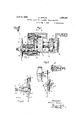
- Figure 1 is a section through a cutting device having a planet-like moved cutting knife.
- Figure 2 'is a corresponding section through a'modification.
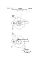
- Figure 3 is a side-view to Fig.
- Figure 4 is a side-view of again another constructional form of the cutting device.
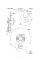
- Figure 5 is a section through a modification, in which the grinding disk is arranged centrically with respect to the axle of the knife carrier.
- Figure 6 is a front-view of the of Fi 5 located at the righthand end of this figure, and Figures 7 and 8 are similar views as 5 and 6,but relate to another modification.
- the circular knife 17. is clamped fast between disks 7c and.
- the axle 2] is firmly connected with a cogwheel 12, viz, a planet wheel, which meshes with a large cogged ring 1 having internal toothing and being firmly connected with the stationary casing b.
- the knife 91 is, therefore, turned around the axis of the axle i, as well as around the axis of the shaft a
- the ratio of transmission between the cog-wheels p and 9" is so chosen that it is a whole multiple plus such a part of one revolution of the knife that during the several consecutive rotations of the member 7' and the casing as always another portion of the circumference of the knife edge contacts with the grinding disk 0.
- This disk can be arranged stationary in the frame of the machine, but in an oblique posiof any suitable mechanism) the knife contacts at the end of its axial forward movement with the grinding disk and is acted on by it. If the knife is to be ground in known manner on both sides of its cutting edge, two grinding disks must be provided, of which the second lies counter to the first, as will be clear without a more detailed explanation.
- the knife is rotated by a belt or a cord.
- 1 denotes the knife carrier and 2 the axle of the same.
- the disk-shaped knife carrier 1 supports in its rim a shaft 3 to which the circular knife 4 is to be attached.
- Concentrically with respect to the axle 2 astationary nonrotating belt pulley or rope pulley 6 is arranged at the frame of the machine, for instance at a standtwo pulleys andtransmits the motion from the pulley 6 to the pulley 8. This latter is considerably smaller than the other pulley.
- the ratio of transmission must be so chosen that the knife 15 performs twelve revolutions while its carrier 14: performs only one.
- 0 denotes the grinding disk (also in Fig. t).
- Figs. 2 and 3 may cooperate with two grinding disks.
- the one acts on one side of the cutting edge, the other 011 the other cutting edge of the circular knife.
- two or more grinding disks may be distributed around the knife carrier, for instance a second grinding disk o may be arranged as shown in dotted lines in Fig. 3.
- the ratio of transmission then may be a correspondingly lower one.
- the axial motion of the knife can be brought about not only (as has already been mentioned in the introductory part of this specification) by moving the knife carrier axially, but also by a tumbling motion of the same.
- the knife can be clamped in an oblique position, or spirally or helically, between the clamping cheeks, and instead of the driving cog-wheel, or of belt or rope drive, friction drive can be used, or an independent electric motor for rotating the knife may be attached to the knife carrier, and so on.
- Figs. 5 and 6 If denotes the shaft to which is attached the rotatory knife a. Said shaft is supported eccentrically in a rotatory disk 0'. Counter to the knife a the shaft d is provided with a small cogwheel d meshing with a large cog-wheel 6 made integral with a sleeve encompassing a hollow shaft 7 to which the disk 0 is affixed.
- the wheel 6 is stationary, and the members d 5 and a are moved round in a circular path when the shaft f is rotated, in that then also the disk 0 is rotated and with it the shaft 6 the pinion (Z and the knife a, this latter contacting, as shown, with the centrally arranged grinding disk i which is affixed to an axle h extending through the hollow shaft and be ing supported by a bearing 6
- the means for rotating the members f and 0 have been omitted in the figure; they may be of any suitable description.
- means (also not shown) are provided for reciprocating the whole device, as indicated by the doubleheaded arrow in Fig. 5. But instead of re ciprocating the device, the knife-carrying disk 0 may be designed. as a tumbling disk, or the knife a may be arranged obliquely with respect to the plane of said disk.
- the object of the reciprocating motion, or of the tumbling motion is to cause the knife to take part in the movement of the strand.
- the grinding disk 15 takes part in the reciprocating movement of the other parts, but does not rotate.
- the knife a which moves round the grinding disk in a planetary manner is ground during its entire path and, therefore, kept continually sharp.
- this latter can be arranged shiftably in axial direction. This may be effected, for instance by providing in the hollow shaft an annular member r having at its bore an obliquely disposed grom e which is engaged by a pin 0 secured to the axle 71, This latter is, therefore,
- the axle 7L is prevented from rotation by a feather in engaging a groove of the bearing [0
- the shape of the groove of the member r is preferably such that the knife contacts with the grinding disk always only for a short time, for instance after the knife has performed one revolution and has penetrated into, or cut, the strand.
- the knife (1. acts relatively to the axis of rotation of the disk 0 carrying the knife, like a sickel-knife, owing to which the cigarette strand 1;,Fig. 6, can be cut through without the disk 0 itself moving towards the strand.
- the de vice operates like a circular knife. 1f the knife is to be ground on both sides of its cutting edge, it is, of course, possible to pro vide two grinding disks, between which the knife is moved round, the two disks being reciprocated alternately by an oblique groove like that of the member 1* or by equivalent means in such a manner that they Contact alternately with the knife edge and grind the respective portions thereof.
- the arrangement and combination of the parts is also in this case such that the grinding disk takes part in eventual axial movements of the knife if this latter is moved in such a direction in order to follow the strand. If the .knife is supported in the manner of a tumbling disk, then, of course, also the grinding disk must be supported in a corresponding manner in order to be able to contact with the knife in the proper manner.
- the number of the se ments 11 can be chosen at liberty, which is true also of the material, although, of course, it must be able ,to grind the knife.
- a cutting device for cigarette strand machines comprising, in combination, a rotatory knife supporting member, a rotatory knife supported eccentrically in said member, and a grinding tool arranged centrally with respect to said rotatory knife supporting member.
- a cutting device for cigarette strand machines comprising, in combination, a rotatory knife supporting member, a rotatory knife supported eccentrically in said member, a grinding tool arranged centrally with respect to said rotatory knife supporting member, and means for moving said tool axially.
- a cutting device for cigarette strand machines comprising, in combination, a rotatory knife supporting member, a rotatory knife supported eccentrically in said member, and a grinding tool arranged centrally with respect to said rotatory knife supporting member and being composed of grinding segments which are separated from each other by non-grinding segments.
- a rotary circular cutting knife having an unbroken cutting edge and a rotary grinding tool mounted relative to the cutting edge to uniformly contact therewith; and means forrevolving the knife about the rodeo that the entire circumference of the said knife about the tool is evenly ground and maintained in true circular contour.
Landscapes
- Finish Polishing, Edge Sharpening, And Grinding By Specific Grinding Devices (AREA)
Description
M. BERGER April 5, 1932..
CUTTING DEVICE FOR CIGARETTE STRAND IACHINES Filed Aug. 7, 1928 5 Sheets-Sheet 1 Jame/2 802-: Ma #214171. Be rye r" M. BERGER April 5, 1932.
CUTTING DEVICE FOR CIGARETTE STRAND IACHINES Filed Aug. 7, 1938 s Sheets-Sheet 2 April 5, 1932. BERGER 1,852,397
CUTTING DEVICE FOR CIGARETTE STRAND IACHINES M... Filed Aug. 7, 1928 3 Sheets-Sheet 5 iii fatented Apr. 5, 1932 UNITED STATES PATENT OFFICE MARTIN BERGER, 0F DRESDEN-FREITAL, GERMANY, ASSIGNOR T0 UNITED CIGARETTE MACHINE COMPANY AKTIENGESELLSGHAFT, OF DRESDEN, GERMANY CUTTING DEVICE FOR CIGARETTE STRAND MACHINES Application filed August 7, 1928, Serial No. 298,078, and in Germany October 24, 1927.
l Vith the known cigarette machines the individual cigarettes are severed off the continually moved cigarette strand, as a rule, by means of a continually rotating cutting knife of circular or sickle-like shape supported usually in a reciprocating bearing member carried by the frame and being so controlled that it penetrates into the cigarette strand and cuts it through while the strand is being moved forwards by the means provided therefor.
If the knife is circular, its penetration into the strand is brought about generally in this way that it is supported eccentrically in its rotating bearing member so that the kn fe aide, irrespective of its rotation around its own axis, moves also on a circular path around the axis of said knife bearing member. In order to obtain unobjectionable cut ting of the strand in spite of its usual high speed, care must be taken that the knife while rotating contacts with a suitable grinding tool and is re-ground by the same.
Now, it is the object of the present invention to arrange the grinding or re-grinding tooi in such a manner or, in other words, to regulate the movement of the knife relatively to the grinding tool in such a manner, that the cutting edge of the knife is re-ground effectively and unobjectionably while the strand cutting device is in operation, It is of no consequence whether the axial movement of the cutting edge in the direction of the strand is effected by an axial reciprocation of the knife axle or of the knife axle bearing member, or by a tumbling movement of this member, or by a screw-like arrangement of the knife at the circumference of said bearing member, or in any other suitable way.
As the contact between the grinding tool and the knife takes place only during a comparatively short period of time, viz. only when the cutting edge has arrived at its extreme final positions in axial direction, it is suited to the purpose to design the arrangement and combination of the parts concerned in such a manner that during the successive grinding operations always other parts of the cutting edge are ground so that it is Warranted that, in fact, at least during a plurality of successive Working phases, the entire circumference of the knife will be ground circularly in uniform manner.
This can, according to the invention, be attained in various Ways, dependent upon whether the knife is operated positively, for instance by a cog-wheel gearing, or by means of a belt or cord. In the first of these cases (of course, also chain-wheel drives and other positively operating members can be employed and will render the same effect) and if the knife is driven ina certain distinct 'atio with respect to the number of revolutions of the knife carrier, then the ratio of transmission is, according to this invention, so chosen that in the moment of contact of the grinding disk and the knife always other parts of this latter are acted on. Supposing, for instance, that during each such contact about 30 of the circumference of the knife, or about of this circumference respectively, is being ground, then the ratio of transmission can be chosen 12:13, or 12:25, or 12 37, and so on, so that at every rotation of the knife carrier the knife itself performs one revolution, or two or more revolutions, plus 30, in consequence whereof always other parts of the knife will be ground.
If the knife is driven independently of the rotation of its carrier, for instance by a belt or a cord, its number of revolutions is, according to this invention, so chosen that it is very high in proportion to the number of rotations of the knife carrier so that during a comparatively small angle of rotation through which said carrier passes while it contacts with the grinding disk, the knife has made already one complete revolution and has been ground along its entire circumference. The accurate proportion between the number of revolutions of the knife carrier and the knife itself depends upon the circumstances of the individual case, for instance upon the shape of the grinding disk and upon the degree of accuracy demanded. It can be assumed that a contact between the knife and its carrier can be maintained while this latter moves through an angle of about 30. If the pressure between the knife and the grinding disk is permitted to vary within wide limits that number of degrees can be surpassed, but if the accuracy required is to be very great, it is advisable to remain below that limit. The knife must then so rotate that it performs a complete revolution during that time in which the knife carrier moves through an arc of 30, or less or more, as the case may be. Thus, it will be necessary that in the normal case stated in which the carrier is in contact with the grinding tool while moving through an are or angle of 30, the knife rotates with twelve times the speed of the knife carrier. In order to ob viate, if the accuracy demanded is particularly great, too quick rotation of the knife which islikely to entail constructive difficulties, several grinding disks can be distributed around the knife in proper distances from one another so that they act successively and each of them grinds a certain distinct part of the circumferential edge of the knife.
Another construction form of the present improved grinding device affords the possibilit of renderin the 'rin'din )rocedure at b D D the eccentrically supported circular knife particularly simple, in that the grinding tool is arranged concentrically with respect to the rotating knife carrier in such a manner that either it is in constant contact with the knife or is made to contact with it only during certain predeterinined periods of time. ,To'attain'this latter purpose the grinding tool can be moved axially with respect to the cutting knife by means of suitable control members, or it can be composed of segments in" such a manner that there is between each two active, i. e. grinding, segments a segment consisting of a non-grinding material. In this case the grinding means need not be moved axially with respect to the cutting knife, and in spite thereof burning of the knife and smearing of the grinding disk will be prevented. It is, of course, possible to give the grinding disk also in this case an additional movement.
The invention is illustrated diagrammatically and by way of example on the accon panying drawings on which Figure 1 is a section through a cutting device having a planet-like moved cutting knife. Figure 2 'is a corresponding section through a'modification. Figure 3 is a side-view to Fig. Figure 4 is a side-view of again another constructional form of the cutting device. Figure 5 is a section through a modification, in which the grinding disk is arranged centrically with respect to the axle of the knife carrier. Figure 6 is a front-view of the of Fi 5 located at the righthand end of this figure, and Figures 7 and 8 are similar views as 5 and 6,but relate to another modification. In Fig. 1, the circular knife 17. is clamped fast between disks 7c and. m firmly connected with an axle 2' connected in turn with a shaft a by means of an intermediate member f. The axle i is supported in ball bearings g and 7b enclosed in a casing 00 projecting forth from a disk 20 firmly connected with the intermediate member All these parts are enclosed in an outer casing b enclosing also ball bearings 0 and (Z supporting the shaft a with its driving cog-wheel a. \Vhen the shaft a is turned, also the member 7" with the disk 02 and the casing w are turned, in consequence whereof the knife n is moved round in a planetary manner. The power for rotating the shaft a is supplied by the main drive of the machine, and transmitted by the wheel 0. The axle 2] is firmly connected with a cogwheel 12, viz, a planet wheel, which meshes with a large cogged ring 1 having internal toothing and being firmly connected with the stationary casing b. The knife 91 is, therefore, turned around the axis of the axle i, as well as around the axis of the shaft a Now, according to this invention the ratio of transmission between the cog-wheels p and 9" is so chosen that it is a whole multiple plus such a part of one revolution of the knife that during the several consecutive rotations of the member 7' and the casing as always another portion of the circumference of the knife edge contacts with the grinding disk 0. This disk can be arranged stationary in the frame of the machine, but in an oblique posiof any suitable mechanism) the knife contacts at the end of its axial forward movement with the grinding disk and is acted on by it. If the knife is to be ground in known manner on both sides of its cutting edge, two grinding disks must be provided, of which the second lies counter to the first, as will be clear without a more detailed explanation.
Concerning Fig. 1 it is assumed that the knife performs two revolutions while the easing m performs one revolution, and if the knife contacts with the grinding disk on a length of way amounting to 30 of the path of the knife round the axis of the shaft a the ratio of transmission must be not exactly 1 z 2, but 12:25.
In the example shown in Figs. 2 and 3, the knife is rotated by a belt or a cord. 1 denotes the knife carrier and 2 the axle of the same. The disk-shaped knife carrier 1 supports in its rim a shaft 3 to which the circular knife 4 is to be attached. Concentrically with respect to the axle 2 astationary nonrotating belt pulley or rope pulley 6 is arranged at the frame of the machine, for instance at a standtwo pulleys andtransmits the motion from the pulley 6 to the pulley 8. This latter is considerably smaller than the other pulley. it is obvious that the knife is rotated around its own axis, as well as around the axle .2, the 'atio depending, of course, upon the difference between the diameters of the pulleys, and it is, consequently, in order to have the grinding disk act always on another portion of the knife, necessary to chose the proper ratio.
If a belt or a rope is used as driving means, it is, of course, possible to drive the pulley 6 separately, as in Fig. e. In this instance, 9 denotes the driving pulley, the shaft 10 of which is supported in the standard 11, and firmly connected with a smaller pulley 13 driven by a belt or rope of its own, as shown. The pulley 9, is therefore, driven independently of the knife-carrying disk 14. lVith this arrangement and combination of parts the number of revolutions of the pulley 9 and the ratio of transmission between it and the knife 15 must be so regulated that this latter performs a complete revolution while it contacts with the grinding disk. tarting from the assumption that the knife and the grinding disk can contact with one another with suitlicient accuracy while the disk 14 passes through 30 of its path round the axis of the shaft 10, the ratio of transmission must be so chosen that the knife 15 performs twelve revolutions while its carrier 14: performs only one. 0 denotes the grinding disk (also in Fig. t).
As has already been c escribed with reference to Fig. 1, also the modifications shown in Figs. 2 and 3, as well as in Fig. l, may cooperate with two grinding disks. This is illustrated by way of example in Fig. 2 in which 17 and 18 are the two grinding disks. The one acts on one side of the cutting edge, the other 011 the other cutting edge of the circular knife. If, desired, two or more grinding disks may be distributed around the knife carrier, for instance a second grinding disk o may be arranged as shown in dotted lines in Fig. 3. The ratio of transmission then may be a correspondingly lower one.
The constructive details of the device may be varied in several respects without departing from the essence of the invention. Thus, for instance. the axial motion of the knife can be brought about not only (as has already been mentioned in the introductory part of this specification) by moving the knife carrier axially, but also by a tumbling motion of the same. Besides, the knife can be clamped in an oblique position, or spirally or helically, between the clamping cheeks, and instead of the driving cog-wheel, or of belt or rope drive, friction drive can be used, or an independent electric motor for rotating the knife may be attached to the knife carrier, and so on.
Concerning now the modification illustrated in Figs. 5 and 6, If denotes the shaft to which is attached the rotatory knife a. Said shaft is supported eccentrically in a rotatory disk 0'. Counter to the knife a the shaft d is provided with a small cogwheel d meshing with a large cog-wheel 6 made integral with a sleeve encompassing a hollow shaft 7 to which the disk 0 is affixed. The wheel 6 is stationary, and the members d 5 and a are moved round in a circular path when the shaft f is rotated, in that then also the disk 0 is rotated and with it the shaft 6 the pinion (Z and the knife a, this latter contacting, as shown, with the centrally arranged grinding disk i which is affixed to an axle h extending through the hollow shaft and be ing supported by a bearing 6 The means for rotating the members f and 0 have been omitted in the figure; they may be of any suitable description. Besides, means (also not shown) are provided for reciprocating the whole device, as indicated by the doubleheaded arrow in Fig. 5. But instead of re ciprocating the device, the knife-carrying disk 0 may be designed. as a tumbling disk, or the knife a may be arranged obliquely with respect to the plane of said disk. The object of the reciprocating motion, or of the tumbling motion, is to cause the knife to take part in the movement of the strand.
The grinding disk 15 takes part in the reciprocating movement of the other parts, but does not rotate. The knife a which moves round the grinding disk in a planetary manner is ground during its entire path and, therefore, kept continually sharp.
In order to prevent strong wear and tear of the knife by the grinding disk, this latter can be arranged shiftably in axial direction. This may be effected, for instance by providing in the hollow shaft an annular member r having at its bore an obliquely disposed grom e which is engaged by a pin 0 secured to the axle 71, This latter is, therefore,
moved to and fro when the shaft 7 with the member r rotates. The axle 7L is prevented from rotation by a feather in engaging a groove of the bearing [0 The shape of the groove of the member r is preferably such that the knife contacts with the grinding disk always only for a short time, for instance after the knife has performed one revolution and has penetrated into, or cut, the strand.
It is obvious that with this modification the knife (1. acts relatively to the axis of rotation of the disk 0 carrying the knife, like a sickel-knife, owing to which the cigarette strand 1;,Fig. 6, can be cut through without the disk 0 itself moving towards the strand. But relatively to the grinding disk the de vice operates like a circular knife. 1f the knife is to be ground on both sides of its cutting edge, it is, of course, possible to pro vide two grinding disks, between which the knife is moved round, the two disks being reciprocated alternately by an oblique groove like that of the member 1* or by equivalent means in such a manner that they Contact alternately with the knife edge and grind the respective portions thereof.
The modification shown in Figs. 7 and 8 is distinguished'from that just dealt with by the feature that the grinding disk 2' is not axially moved with respect to the knife a Now, in order to provide in spite thereof for only temporary contacts of the knife with the grinding disk this latter is composed of segments 2' of a grinding material and of segments of another material which is unsuited for grinding, for instance a metal or the like. The plane of the segments 2' lies below the plane of the segments 6 It is, however, also possible to leave empty spaces between the grinding segments. The thus designed grinding disk is arranged in Figs. 7 and 8 in the same manner as in Figs. 5 and 6, that is to say, it is not rotated, although it is, of course, possible to turn the grinding disk with any desired speed, if this manner of operation is preferred. In the whole, the arrangement and combination of the parts is also in this case such that the grinding disk takes part in eventual axial movements of the knife if this latter is moved in such a direction in order to follow the strand. If the .knife is supported in the manner of a tumbling disk, then, of course, also the grinding disk must be supported in a corresponding manner in order to be able to contact with the knife in the proper manner.
The number of the se ments 11 can be chosen at liberty, which is true also of the material, although, of course, it must be able ,to grind the knife.
I claim: 1. A cutting device for cigarette strand machines, comprising, in combination, a rotatory knife supporting member, a rotatory knife supported eccentrically in said member, and a grinding tool arranged centrally with respect to said rotatory knife supporting member.
2. A cutting device for cigarette strand machines, comprising, in combination, a rotatory knife supporting member, a rotatory knife supported eccentrically in said member, a grinding tool arranged centrally with respect to said rotatory knife supporting member, and means for moving said tool axially.
3. A cutting device for cigarette strand machines, comprising, in combination, a rotatory knife supporting member, a rotatory knife supported eccentrically in said member, and a grinding tool arranged centrally with respect to said rotatory knife supporting member and being composed of grinding segments which are separated from each other by non-grinding segments.
4. In a cutting device of the kind described, the combination of a rotary circular cutting knife having an unbroken cutting edge and a rotary grinding tool mounted relative to the cutting edge to uniformly contact therewith; and means forrevolving the knife about the rodeo that the entire circumference of the said knife about the tool is evenly ground and maintained in true circular contour.
5. In a cutting device of the kind described,
the combination of a rotary circular cutting
Applications Claiming Priority (1)
| Application Number | Priority Date | Filing Date | Title |
|---|---|---|---|
| DE1852397X | 1927-10-24 |
Publications (1)
| Publication Number | Publication Date |
|---|---|
| US1852397A true US1852397A (en) | 1932-04-05 |
Family
ID=7746076
Family Applications (1)
| Application Number | Title | Priority Date | Filing Date |
|---|---|---|---|
| US29807828 Expired - Lifetime US1852397A (en) | 1927-10-24 | 1928-08-07 | Cutting device for cigarette strand machines |
Country Status (1)
| Country | Link |
|---|---|
| US (1) | US1852397A (en) |
Cited By (2)
| Publication number | Priority date | Publication date | Assignee | Title |
|---|---|---|---|---|
| US2822844A (en) * | 1954-07-12 | 1958-02-11 | Und Eisengiesserei A Heinen G | Tobacco cutter having automatically adjustable mouthpiece |
| US4643061A (en) * | 1985-05-30 | 1987-02-17 | Gerber Scientific Inc. | Rotary blade sheet material cutter with sharpener |
-
1928
- 1928-08-07 US US29807828 patent/US1852397A/en not_active Expired - Lifetime
Cited By (2)
| Publication number | Priority date | Publication date | Assignee | Title |
|---|---|---|---|---|
| US2822844A (en) * | 1954-07-12 | 1958-02-11 | Und Eisengiesserei A Heinen G | Tobacco cutter having automatically adjustable mouthpiece |
| US4643061A (en) * | 1985-05-30 | 1987-02-17 | Gerber Scientific Inc. | Rotary blade sheet material cutter with sharpener |
Similar Documents
| Publication | Publication Date | Title |
|---|---|---|
| US8826785B2 (en) | Cutting machine | |
| US1852397A (en) | Cutting device for cigarette strand machines | |
| US2579642A (en) | Mechanical movement | |
| US3410272A (en) | Apparatus for removing sprouts from a brussels sprouts plant | |
| US3299778A (en) | Circular saws | |
| JPH0966414A (en) | Cutting device of steel pipe | |
| US3604162A (en) | Grinders for helical cutoff knives | |
| US1988215A (en) | Flying shear | |
| EP1060855A2 (en) | Apparatus for cutting stone materials, such as granite, marble or the like | |
| US2802320A (en) | Grinding attachment for machine tools | |
| US2297468A (en) | Sharpening device for the rotating sickle knife of cigarette rod machines | |
| US2012489A (en) | Slicing machine | |
| US475328A (en) | Band-saw mill | |
| US131962A (en) | Improvement in machines for triwswisng metallic bands | |
| SU766894A1 (en) | Machine for pressing viscous materials | |
| US1487589A (en) | Machine for milling tooth sockets in saw blades | |
| US1949340A (en) | Cutting apparatus for continuous rod cigarette making machines | |
| US2823748A (en) | Shear | |
| US262258A (en) | Veneer-cutting machine | |
| US1713892A (en) | Tool-moving device for crank lathes | |
| US1984040A (en) | Cut-off mechanism | |
| US980561A (en) | Cylinder-grinder for leather-shaving machines. | |
| US1778875A (en) | Slicing machine | |
| US1363999A (en) | Centrifugal honey-extractor | |
| US2886083A (en) | Cigarette rod cutter |