US1852389A - Can opener - Google Patents
Can opener Download PDFInfo
- Publication number
- US1852389A US1852389A US391784A US39178429A US1852389A US 1852389 A US1852389 A US 1852389A US 391784 A US391784 A US 391784A US 39178429 A US39178429 A US 39178429A US 1852389 A US1852389 A US 1852389A
- Authority
- US
- United States
- Prior art keywords
- blade
- opener
- wheel
- handle
- guide member
- Prior art date
- Legal status (The legal status is an assumption and is not a legal conclusion. Google has not performed a legal analysis and makes no representation as to the accuracy of the status listed.)
- Expired - Lifetime
Links
- 238000005520 cutting process Methods 0.000 description 21
- 238000010276 construction Methods 0.000 description 2
- 238000010008 shearing Methods 0.000 description 2
- 210000003811 finger Anatomy 0.000 description 1
- 210000005224 forefinger Anatomy 0.000 description 1
Images
Classifications
-
- B—PERFORMING OPERATIONS; TRANSPORTING
- B67—OPENING, CLOSING OR CLEANING BOTTLES, JARS OR SIMILAR CONTAINERS; LIQUID HANDLING
- B67B—APPLYING CLOSURE MEMBERS TO BOTTLES JARS, OR SIMILAR CONTAINERS; OPENING CLOSED CONTAINERS
- B67B7/00—Hand- or power-operated devices for opening closed containers
- B67B7/30—Hand-operated cutting devices
- B67B7/32—Hand-operated cutting devices propelled by rotary gears or wheels around periphery of container
Definitions
- This invention relates to can openers.
- the primary object of the invention is to provide a can opener in which a traction wheel and a fixed blade are moved on a sub- .t stantially arcuate path toward each other to cause the puncturing of the top of the can by the blade and to grlp the rim of the can between the wheel and the blade; means being provided to allow the rotation of the wheel W thereby to move the blade around the inner periphery of the rim of the can, shearing old the top of the can thereat; the initial rotation of the wheel causing the said puncture oi the can, the strain exerted by the han- 3W dles being very slight.
- Another object of the invention is the provision out a fixed blade for a can Opener, the cutting edge of which tilts the top of the can upwardly at an angle, before the top is comm pletely severed from the can, thus facilitating the removal of the top from the can; an edge oi the blade being so formed as to lim1t the angle to which the top is tilted by the opener.
- Another object of the invention is the construction of a can opener of the above mentioned type, with a guide member for the traction wheel, which is pivoted on one of said handles, and guided by the other handle oi the can opener; the said member being bent to cause the can to be held by said can opener at a proper angle, out of engagement with the face of the traction wheel and against the underside of the rim of the can.
- Fig. 1 is a side view of the can opener
- Fig. 2 is a sectional view of the line 2-2 of Fig. 3; i
- Fig. 3 is a side view of the can opener showmg the relative disengaged positlon of the blade and the traction wheel;
- Fig. 4 is an end view of the can opener in cutting position relatively to the can;
- Fig. 5 is a side view of the can opener, and the. can in position when the cut is nearly completed, showing the tilting of the top of the can;
- Fig. 6 is a side view of the cutting blade on of the can opener.
- Fig. 7 is a face view of the cutting blade.
- a handle 6 has an en: larged end 7 thereon, to which is ivotally secured another handle 8 by a suitable pivot pin 9.
- another pivot 11 On the. enlarged end 7 and spaced from the pivot 9 is provided another pivot 11 by means of which a guide member 12 is swingably attached to said enlarged end, An edge 13 of the guide member portion on the It end 7 is curved.
- the adjacent end 14 of the other handle 8 is bent and rebent to .form a U shaped recess 16 fitting over the curved end of the guide member 12, to slidably guide a c the same.
- a traction wheel 17 On one side of the depending portion of the guide member 12 is rotatably held a traction wheel 17.
- the pin 18 of the wheel 17 extends to the other side of the guide member 12, and has a wing handle 19 mounted at thereon, thru which the wheel 17 may be rotated at will.
- the outer edges 6f the bent end 141- of the handle 8, on the side nearer the traction wheel 1'? are flared outwardly to form flanges 20. These flanges 20 provide a larger bearing surface thereat, for the rim of the can to be opened.
- a cutting blade 21 In the outer face of the handle end- 14 is fixedly held a cutting blade 21, by means of a screw 22.
- the cutting edge of said blade 21 extends in the direction of the wheel 17 so that when the handles are moved into gripping position, the cutting edge of the blade 21 overlaps the wheel 17. It is to be noted that the, blade 21 is disposed at an I han ate movement of the depending portion of theguide 12 and. the wheel 17 thereon, toward the cutting blade 17.
- the periphery of the traction wheel 17 is held a ainst the underside of the rim 23 of the ca 24.
- the traction wheel 17 is preferably toothed, to permit the firm engagement thereof with the rim 23.
- the grip portions of the handles 6 and 8 are then moved toward each other, but it is notnecessary to accomplish the piercing of the can by the force exerted upon the grip portions of the handles 6 and 8. ,By giving a sli ht strain to the handles 6 and 8 when in t eright position to pierce the top of the can, the opener is held in position. Then the traction wheel 17 is turned slightly.
- the can As the can is turned, it is held by the opener, as a unitary handle, and the'edge of the top isadvanced against the cutting edge of the blade 21, and issheared thereby. During this operation the flanges 20 hold the opener in balanced position, preventin the tilting thereof.
- This guiding action 1s especially important when the can opener must follow a s arp curve of the can contour, such as the corners of a square can.
- the guide member 12 is at all times, during the cutting, firmly interlocked with the handles and the can, absorbing all the strain from the handles due to cutting.
- the cutting edge of the blade 21 is so formed as to cause the tilting of the top, thus bringpierce ing a portion of the top out ofthe can, permitting the grasping and the ready removal thereof.
- the cutting edge of the blade 21 is formed in a substantially V-shaped chamfered edge 26, having a rounded intermediate point 27.
- the corner 28 0f the edge 26 is squared, the chamfer of the edge endingabruptly thereat.
- the bottom of the blade at the edges is slightly convex.
- the can is rotated by r the wheel 17 so that the top thereof moves of, inthe manner indicated in dotted lines in Fig. 5.
- the half ofthe top of the side of the squared corner-28 tilts upwardly, out of the can 24. This action, in some instances, may cause the top to entirely fly off the can.
- the squared corner 28 limits the amount oftilting of the .top.
- the can opener is removed from the can by ,moving the outer ends'of the handles 6 and 8 apart from each other, whereby the wheel 17 is moved away from the rim. 23, and the grilplon the rim 23 is released.
- the free end and partly the outer side edges of the dependin portion of the guide member 12 are bent beyond the plane of the wheel 17, forming guides 29.
- the guides 29 rest against the side of the can, directly below the wheel 17 ,causing the can to assume the angular position, shown in Fig. 4, and insuring the contact of the toothed peri hery of the wheel f 17 with the underside of t e rim 23, without permitting any frictional contact between the si7de of the can 24, and the face of the wheel 1
- the can is not held by the operator of the opener,.but by thegripped and the can remains firmly locked in the opener, so that it cannot slip during the operation of the opener.
- the can opener heretofore described may be used on either round or square or any other shape cans.
- the cut .top or cover is tilted not only around the respective diameter of the top 'but also upwardly around an axis tangentialto the top at said small uncut edge portion of the rim, thus holding the rim thereat, to a position approximately parallel with the plane of the handles.
- the can opener blade tilts, bends, or folds the cut cover vertically, that is from the edge of the rim upward, the operator can at will, while holding the can with the can opener, push forward a forefin ger of his left hand, thereby to hold the can and also to press the cut cover against the face of the blade.
- a receptacle or holding finger may be provided on the opener itself, so as to reeeive the cut cover therein.
- a can opener in a can opener, two handles pivotally secured to each other intermediate their ends; a guide member pivoted on one end of one handle. the respective end of the other handle being formed with a recess to guide said guide member therein; a traction wheel rotatable on a depending portion of the guide member; a cutting blade fixed on the recessed end of the second handle in overlapping relation to said traction wheel when the opener is in operative position, said wheel and said blade, when moved in said overlapping relation, being adapted to grip the rim of a can therebetween; and means to permit rotation of the wheel thereby to rotate the can to rotate the periphery of the top thereof against the said blade to be cut thereat.
- a can opener in a can opener, two handles pivot-ally secured to each other intermediate their ends; a guide member pivoted on one end of one handle, the respective end of the other handle being formed with a recess to guide said guide member therein; a traction wheel rotatable on a depending portion of the guide member; a cutting blade fixed on the recessed end of the second handle in overlapping relation to said traction wheel when the opener is in operative position, said wheel and said blade, when moved in said overlapping relation, being adapted to grip the rim of a can therebetween; means to permit rotation of the wheel thereby to rotate the can to rotate the periphery of the top thereof against the said blade to be cut thereat; and project-ions on said guide arranged to hold the can in inclined position, away from the face of the wheel.
- a can opener In a can opener, two handles pivotally secured to each other intermediate their ends; a guide member pivoted on one end of one handle, the respective end of the other handle being formed with a recess to guide said guide member therein; a traction wheel at rotatable on a depending portion of the guide member; a cutting'blade fixed on the recessed end of'thesecond handle in overlapping relation to said traction Wheel when the opener is in operative position, said wheel and said blade, when moved in said overlapping relation, being adapted to grip the rim ofa can therebetween; and means to permit rotation of the wheel, thereby to r0- tate the can to rotate the periphery of the top thereof, against the said blade, to be out thereat, said blade being adapted to tilt the top of the can when theblade is nearing the starting point of the cut.
- two handles pivotally secured to each other intermediate their ends; a guide member pivoted on one end of one handle, the respective end of the other handle being formed with a recess to guide said guide member therein; a traction wheel rotatable on a depending portion of the guide member; a cutting blade fixed 0n the recessed end of the second handle in overlapping relation to said traction wheel when the opener is in operative posltion, said wheel and said blade, when moved in said overlapping relation, being adapted to grip the rim of a cam therebetween; means to permit rotation of the wheel thereby to rotate the can to rotate the periphery of the top thereof against the said blade to be cut thereat; and projections on said guide arranged to hold the can ininclined position, away from the face of the wheel, said blade being adapted to tilt the top of the can, when the blade is nearing the starting point of the cut.
- a can opener In a can opener, two handles pivot'ally secured to each other intermediate their ends; a guide member pivoted on one end of one handle, the respective end of the other handle being formed with a recess to guide said guide member therein; a traction wheel rotatable on a depending portion of the guide member; acutting blade fixed 'on the recessed end of the second handle in overlapping relation to said traction wheel when the opener is in operative position, said wheel and said blade, when moved in saidoverlapping relation, being adapted to grip the rim of a can therebetween and means to permit rotation of the wheel, thereby to rotate the can to rotate the periphery of the top thereof against the said blade, to be cut thereat, said guide member having arcuate edges at the end thereof riding in said recess of the other handle, coacting with said recess for holding the opener against accidental disengagementfrom the rim.
- a can opener two pivoted handles, a pivoted wheel carrying member on one handie; a traction wheel rotatably secured on said member; an arcuate guide formed at the corresponding end of the other handle to receive and guide said member on an arouate path; a fixed blade on the guide end of 4- a I r 1,852,889
- the second handle arranged to the riin of a can ⁇ between the blade an t e wheel
- a can opener two pivoted handles, a ivoted wheel carrymg member on one han t 1e; a traction Wheel rotatably secured on said member; an arcuate guide formed at the correspondingend of the other handle to receive and ide said member on an arcuate path; a xedblade on the guide end of the second handle, arranged to grip the rim of a can between the blade and t e wheel, when moved toward each other by the pivotal movement of the handles, and to pierce the top of a can thereat; and means to permit rotation of the traction wheel at will,
- a can opener two handles pivotally secured to each other intermediate their ends; a guide member pivoted on one end of one handle, the respective end of the other handle being formed with a recess to guide said guide member therein; a traction wheel rotatable on a depending portion of the guide member; a cutting blade fixed on the recessed end of the second handle, in over lapping relation to said traction wheel,
- said wheel and said blade when moved in said overlapping relation being adapted to grip the rim of a can therebetween; a guide flange iormed on the edge of said recessed end, on the side nearer to said traction wheel, for guiding engagement with the rim of the can; and means to permit rotation of the wheel thereby to rotate the can to rotate the periphery of the top'thereof against the said blade to be cut thereat.
Landscapes
- Engineering & Computer Science (AREA)
- Mechanical Engineering (AREA)
- Devices For Opening Bottles Or Cans (AREA)
Description
A. ZIDOVEC CAN OPENER April 5, 1932.
Filed Sept. 11, 1929 INVENTOR. ,4u6 U7" 2/519 #56 Patented Apr. 5, 1932 UNITED STATES PATENT OFFICE AUGUST zmovm, or an: memo, sun-om can 0211mm Application ma September 11, 1929. Serial no. 881,784.
This invention relates to can openers.
The primary object of the invention is to provide a can opener in which a traction wheel and a fixed blade are moved on a sub- .t stantially arcuate path toward each other to cause the puncturing of the top of the can by the blade and to grlp the rim of the can between the wheel and the blade; means being provided to allow the rotation of the wheel W thereby to move the blade around the inner periphery of the rim of the can, shearing old the top of the can thereat; the initial rotation of the wheel causing the said puncture oi the can, the strain exerted by the han- 3W dles being very slight.
Another object of the invention is the provision out a fixed blade for a can Opener, the cutting edge of which tilts the top of the can upwardly at an angle, before the top is comm pletely severed from the can, thus facilitating the removal of the top from the can; an edge oi the blade being so formed as to lim1t the angle to which the top is tilted by the opener.
Another object of the invention is the construction of a can opener of the above mentioned type, with a guide member for the traction wheel, which is pivoted on one of said handles, and guided by the other handle oi the can opener; the said member being bent to cause the can to be held by said can opener at a proper angle, out of engagement with the face of the traction wheel and against the underside of the rim of the can.
l'lther objects and advantages are to provide a can opener that will be superior in point of simplicity, inexpensiveness of construction, positiveness of operation, and facility and convenience in use and general eiliciency.
in this specification and the annexed drawings, the invention is illustrated in the term considered to be the best, but it is to be s understood that the invention is not limited to such form, because it may be embodied in other forms; and it is also to be understood that in and by the claims following the description, it is desired to cover the invention in whatsoever form it may be embodied.
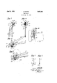
The invention is clearly illustrated in the accompanying drawings wherein Fig. 1 is a side view of the can opener;
Fig. 2 is a sectional view of the line 2-2 of Fig. 3; i
Fig. 3 is a side view of the can opener showmg the relative disengaged positlon of the blade and the traction wheel;
Fig. 4 is an end view of the can opener in cutting position relatively to the can;
' Fig. 5 is a side view of the can opener, and the. can in position when the cut is nearly completed, showing the tilting of the top of the can; t
Fig. 6 is a side view of the cutting blade on of the can opener; and
Fig. 7 is a face view of the cutting blade.
In my can opener a handle 6 has an en: larged end 7 thereon, to which is ivotally secured another handle 8 by a suitable pivot pin 9. On the. enlarged end 7 and spaced from the pivot 9 is provided another pivot 11 by means of which a guide member 12 is swingably attached to said enlarged end, An edge 13 of the guide member portion on the It end 7 is curved. The adjacent end 14 of the other handle 8 is bent and rebent to .form a U shaped recess 16 fitting over the curved end of the guide member 12, to slidably guide a c the same.
On one side of the depending portion of the guide member 12 is rotatably held a traction wheel 17. The pin 18 of the wheel 17 extends to the other side of the guide member 12, and has a wing handle 19 mounted at thereon, thru which the wheel 17 may be rotated at will. The outer edges 6f the bent end 141- of the handle 8, on the side nearer the traction wheel 1'? are flared outwardly to form flanges 20. These flanges 20 provide a larger bearing surface thereat, for the rim of the can to be opened.
In the outer face of the handle end- 14 is fixedly held a cutting blade 21, by means of a screw 22. The cutting edge of said blade 21 extends in the direction of the wheel 17 so that when the handles are moved into gripping position, the cutting edge of the blade 21 overlaps the wheel 17. It is to be noted that the, blade 21 is disposed at an I han ate movement of the depending portion of theguide 12 and. the wheel 17 thereon, toward the cutting blade 17.
In operation, before the grip portions of the handles 6 and 8 are brought toward each other, the periphery of the traction wheel 17 is held a ainst the underside of the rim 23 of the ca 24. The traction wheel 17 is preferably toothed, to permit the firm engagement thereof with the rim 23. The grip portions of the handles 6 and 8 are then moved toward each other, but it is notnecessary to accomplish the piercing of the can by the force exerted upon the grip portions of the handles 6 and 8. ,By giving a sli ht strain to the handles 6 and 8 when in t eright position to pierce the top of the can, the opener is held in position. Then the traction wheel 17 is turned slightly. Inasmuch as the teeth of the wheel 17 are pressed into the rim of the can, the turning of the wheel draws the guide member 12 into the recess 16, thus causing the blade to the top of the can. After the can is plerced the guide member 12 remains firmly locked within said recess 16 thruout the entire cutting operation. This piercing requires aminimum 'efiort due to the shearing action of the angularly disposed blade 21 and the lever-' age exerted thereon by the handles 6 and 8. The wheel 17 is then rotated in a contraclockwise direction, viewing Fig. 5, whereby the can is turned also in a contraclockwise direction, viewing the topof the can. As the can is turned, it is held by the opener, as a unitary handle, and the'edge of the top isadvanced against the cutting edge of the blade 21, and issheared thereby. During this operation the flanges 20 hold the opener in balanced position, preventin the tilting thereof. This guiding action 1s especially important when the can opener must follow a s arp curve of the can contour, such as the corners of a square can. Thus the top is cut out of the can with great facility. The guide member 12 is at all times, during the cutting, firmly interlocked with the handles and the can, absorbing all the strain from the handles due to cutting. A
Usually when the top is completely severed from the rim of a can, it drops on the top of the content of the can, and its removal from the can is diflicult and unsanitary. In order to prevent the dropping of the top into the can, and to facilitate the removal thereof, the cutting edge of the blade 21 is so formed as to cause the tilting of the top, thus bringpierce ing a portion of the top out ofthe can, permitting the grasping and the ready removal thereof. For thls purpose the cutting edge of the blade 21 is formed in a substantially V-shaped chamfered edge 26, having a rounded intermediate point 27. The corner 28 0f the edge 26 is squared, the chamfer of the edge endingabruptly thereat. The bottom of the blade at the edges is slightly convex.
It is to be noted that the can is rotated by r the wheel 17 so that the top thereof moves of, inthe manner indicated in dotted lines in Fig. 5. The half ofthe top of the side of the squared corner-28 tilts upwardly, out of the can 24. This action, in some instances, may cause the top to entirely fly off the can.
However, on my can opener the squared corner 28 limits the amount oftilting of the .top. The can openeris removed from the can by ,moving the outer ends'of the handles 6 and 8 apart from each other, whereby the wheel 17 is moved away from the rim. 23, and the grilplon the rim 23 is released.
order to hold the can 24 on an incline, free from the face of the wheel 17, the free end and partly the outer side edges of the dependin portion of the guide member 12 are bent beyond the plane of the wheel 17, forming guides 29. The guides 29 rest against the side of the can, directly below the wheel 17 ,causing the can to assume the angular position, shown in Fig. 4, and insuring the contact of the toothed peri hery of the wheel f 17 with the underside of t e rim 23, without permitting any frictional contact between the si7de of the can 24, and the face of the wheel 1 It is to be noted that the can is not held by the operator of the opener,.but by thegripped and the can remains firmly locked in the opener, so that it cannot slip during the operation of the opener. The can opener heretofore described may be used on either round or square or any other shape cans.
In connection with the tilting of the cut off can top by the blade, it is to be noted that, the cut .top or cover is tilted not only around the respective diameter of the top 'but also upwardly around an axis tangentialto the top at said small uncut edge portion of the rim, thus holding the rim thereat, to a position approximately parallel with the plane of the handles. When the can opener blade tilts, bends, or folds the cut cover vertically, that is from the edge of the rim upward, the operator can at will, while holding the can with the can opener, push forward a forefin ger of his left hand, thereby to hold the can and also to press the cut cover against the face of the blade. Thus, the cut cover or top of the can is removed together with the detachment of the cam opener. For holding the cut and tilted cover against the face of the blade, a receptacle or holding finger may be provided on the opener itself, so as to reeeive the cut cover therein.
lE-lavin g thus described this invention, what it claim and desire to secure by Letters ?atcut is:
l. in a can opener, two handles pivotally secured to each other intermediate their ends; a guide member pivoted on one end of one handle. the respective end of the other handle being formed with a recess to guide said guide member therein; a traction wheel rotatable on a depending portion of the guide member; a cutting blade fixed on the recessed end of the second handle in overlapping relation to said traction wheel when the opener is in operative position, said wheel and said blade, when moved in said overlapping relation, being adapted to grip the rim of a can therebetween; and means to permit rotation of the wheel thereby to rotate the can to rotate the periphery of the top thereof against the said blade to be cut thereat.
2. in a can opener, two handles pivot-ally secured to each other intermediate their ends; a guide member pivoted on one end of one handle, the respective end of the other handle being formed with a recess to guide said guide member therein; a traction wheel rotatable on a depending portion of the guide member; a cutting blade fixed on the recessed end of the second handle in overlapping relation to said traction wheel when the opener is in operative position, said wheel and said blade, when moved in said overlapping relation, being adapted to grip the rim of a can therebetween; means to permit rotation of the wheel thereby to rotate the can to rotate the periphery of the top thereof against the said blade to be cut thereat; and proiect-ions on said guide arranged to hold the can in inclined position, away from the face of the wheel.
5. In a can opener, two handles pivotally secured to each other intermediate their ends; a guide member pivoted on one end of one handle, the respective end of the other handle being formed with a recess to guide said guide member therein; a traction wheel at rotatable on a depending portion of the guide member; a cutting'blade fixed on the recessed end of'thesecond handle in overlapping relation to said traction Wheel when the opener is in operative position, said wheel and said blade, when moved in said overlapping relation, being adapted to grip the rim ofa can therebetween; and means to permit rotation of the wheel, thereby to r0- tate the can to rotate the periphery of the top thereof, against the said blade, to be out thereat, said blade being adapted to tilt the top of the can when theblade is nearing the starting point of the cut.
a. In a can opener, two handles pivotally secured to each other intermediate their ends; a guide member pivoted on one end of one handle, the respective end of the other handle being formed with a recess to guide said guide member therein; a traction wheel rotatable on a depending portion of the guide member; a cutting blade fixed 0n the recessed end of the second handle in overlapping relation to said traction wheel when the opener is in operative posltion, said wheel and said blade, when moved in said overlapping relation, being adapted to grip the rim of a cam therebetween; means to permit rotation of the wheel thereby to rotate the can to rotate the periphery of the top thereof against the said blade to be cut thereat; and projections on said guide arranged to hold the can ininclined position, away from the face of the wheel, said blade being adapted to tilt the top of the can, when the blade is nearing the starting point of the cut.
5. In a can opener, two handles pivot'ally secured to each other intermediate their ends; a guide member pivoted on one end of one handle, the respective end of the other handle being formed with a recess to guide said guide member therein; a traction wheel rotatable on a depending portion of the guide member; acutting blade fixed 'on the recessed end of the second handle in overlapping relation to said traction wheel when the opener is in operative position, said wheel and said blade, when moved in saidoverlapping relation, being adapted to grip the rim of a can therebetween and means to permit rotation of the wheel, thereby to rotate the can to rotate the periphery of the top thereof against the said blade, to be cut thereat, said guide member having arcuate edges at the end thereof riding in said recess of the other handle, coacting with said recess for holding the opener against accidental disengagementfrom the rim.
6. In a can opener, two pivoted handles, a pivoted wheel carrying member on one handie; a traction wheel rotatably secured on said member; an arcuate guide formed at the corresponding end of the other handle to receive and guide said member on an arouate path;a fixed blade on the guide end of 4- a I r 1,852,889
the second handle, arranged to the riin of a can \between the blade an t e wheel,
,when moved toward each other b the pivotal movement of the handles, an to pierce the top of a can thereat; and means to ]permit rotation of the traction wheel at wi rotate the can, thereby to cause the cutting of the top by said blade.
7. In a can opener, two pivoted handles, a ivoted wheel carrymg member on one han t 1e; a traction Wheel rotatably secured on said member; an arcuate guide formed at the correspondingend of the other handle to receive and ide said member on an arcuate path; a xedblade on the guide end of the second handle, arranged to grip the rim of a can between the blade and t e wheel, when moved toward each other by the pivotal movement of the handles, and to pierce the top of a can thereat; and means to permit rotation of the traction wheel at will,
/ to rotate the can, thereby to cause the cutting of the top by said blade, said guide member being adapted to be firmly interlocked with the handles during the operation of the opener.
8. In a can opener, two handles pivotally secured to each other intermediate their ends; a guide member pivoted on one end of one handle, the respective end of the other handle being formed with a recess to guide said guide member therein; a traction wheel rotatable on a depending portion of the guide member; a cutting blade fixed on the recessed end of the second handle, in over lapping relation to said traction wheel,
when the opener is in operative position, said wheel and said blade, when moved in said overlapping relation being adapted to grip the rim of a can therebetween; a guide flange iormed on the edge of said recessed end, on the side nearer to said traction wheel, for guiding engagement with the rim of the can; and means to permit rotation of the wheel thereby to rotate the can to rotate the periphery of the top'thereof against the said blade to be cut thereat.
In testimony whereof, I have hereunto set my hand at San Francisco, California, this (it day of September, 1929.
AUGUST ZIDOVEC.
Priority Applications (1)
| Application Number | Priority Date | Filing Date | Title |
|---|---|---|---|
| US391784A US1852389A (en) | 1929-09-11 | 1929-09-11 | Can opener |
Applications Claiming Priority (1)
| Application Number | Priority Date | Filing Date | Title |
|---|---|---|---|
| US391784A US1852389A (en) | 1929-09-11 | 1929-09-11 | Can opener |
Publications (1)
| Publication Number | Publication Date |
|---|---|
| US1852389A true US1852389A (en) | 1932-04-05 |
Family
ID=23547934
Family Applications (1)
| Application Number | Title | Priority Date | Filing Date |
|---|---|---|---|
| US391784A Expired - Lifetime US1852389A (en) | 1929-09-11 | 1929-09-11 | Can opener |
Country Status (1)
| Country | Link |
|---|---|
| US (1) | US1852389A (en) |
Cited By (7)
| Publication number | Priority date | Publication date | Assignee | Title |
|---|---|---|---|---|
| US2554420A (en) * | 1948-06-04 | 1951-05-22 | George W Okey | Continuous grip can opener |
| USD277926S (en) | 1982-03-18 | 1985-03-12 | Ivan Chow | Can opener |
| USD326039S (en) | 1990-07-23 | 1992-05-12 | Oxo International L.P. | Can opener |
| USD495571S1 (en) | 2003-07-09 | 2004-09-07 | Wilton Industries, Inc. | Can opener |
| USD748960S1 (en) * | 2014-02-28 | 2016-02-09 | Bradshaw International, Inc. | Can opener |
| USD834904S1 (en) * | 2017-01-05 | 2018-12-04 | Dkb Household Uk Limited | Can opener |
| USD875491S1 (en) * | 2018-06-27 | 2020-02-18 | Mr. Bar-B-Q Products Llc | Can opener |
-
1929
- 1929-09-11 US US391784A patent/US1852389A/en not_active Expired - Lifetime
Cited By (8)
| Publication number | Priority date | Publication date | Assignee | Title |
|---|---|---|---|---|
| US2554420A (en) * | 1948-06-04 | 1951-05-22 | George W Okey | Continuous grip can opener |
| USD277926S (en) | 1982-03-18 | 1985-03-12 | Ivan Chow | Can opener |
| USD326039S (en) | 1990-07-23 | 1992-05-12 | Oxo International L.P. | Can opener |
| USD495571S1 (en) | 2003-07-09 | 2004-09-07 | Wilton Industries, Inc. | Can opener |
| USD748960S1 (en) * | 2014-02-28 | 2016-02-09 | Bradshaw International, Inc. | Can opener |
| USD834904S1 (en) * | 2017-01-05 | 2018-12-04 | Dkb Household Uk Limited | Can opener |
| USD873641S1 (en) | 2017-01-05 | 2020-01-28 | Dkb Household Uk Limited | Can opener |
| USD875491S1 (en) * | 2018-06-27 | 2020-02-18 | Mr. Bar-B-Q Products Llc | Can opener |
Similar Documents
| Publication | Publication Date | Title |
|---|---|---|
| US1852389A (en) | Can opener | |
| US1935680A (en) | Can opener | |
| US1707804A (en) | Kitchen utensil | |
| US2190940A (en) | Can opener | |
| US2237418A (en) | Can opener | |
| US1364016A (en) | Can-opener | |
| US1795478A (en) | Can opener | |
| US1024403A (en) | Bottle-opener. | |
| US1825216A (en) | Can opener | |
| US2554420A (en) | Continuous grip can opener | |
| US2662279A (en) | Device for removing the ends of cans | |
| US1562579A (en) | Can opener | |
| US2311660A (en) | Can opener | |
| US2718055A (en) | Can opener | |
| US1914738A (en) | Can opener | |
| US2818754A (en) | Manually operated serrated lid remover for screw threaded containers | |
| US1657842A (en) | Can opener | |
| US1876421A (en) | Of jlanshto | |
| US2525884A (en) | Can-piercing device | |
| US1402437A (en) | Can opener | |
| US1870938A (en) | Can opener | |
| US2891310A (en) | Can opener | |
| US2091524A (en) | Can opener | |
| US1969868A (en) | Hand can opener | |
| US2079271A (en) | Tin opener |