US1852367A - Train dispatching system for railroads - Google Patents
Train dispatching system for railroads Download PDFInfo
- Publication number
- US1852367A US1852367A US358076A US35807629A US1852367A US 1852367 A US1852367 A US 1852367A US 358076 A US358076 A US 358076A US 35807629 A US35807629 A US 35807629A US 1852367 A US1852367 A US 1852367A
- Authority
- US
- United States
- Prior art keywords
- relay
- circuit
- wire
- selectors
- synchronous
- Prior art date
- Legal status (The legal status is an assumption and is not a legal conclusion. Google has not performed a legal analysis and makes no representation as to the accuracy of the status listed.)
- Expired - Lifetime
Links
Images
Classifications
-
- B—PERFORMING OPERATIONS; TRANSPORTING
- B61—RAILWAYS
- B61L—GUIDING RAILWAY TRAFFIC; ENSURING THE SAFETY OF RAILWAY TRAFFIC
- B61L7/00—Remote control of local operating means for points, signals, or track-mounted scotch-blocks
- B61L7/06—Remote control of local operating means for points, signals, or track-mounted scotch-blocks using electrical transmission
- B61L7/08—Circuitry
- B61L7/085—Common line wire control using synchronous distributors
Definitions
- This invention relates to train dispatching systems, and more particularly to a synchronous selector system for controlling the switch machine and signals of such a dispatching system.
- the present invention contemplates the use of a synchronous selector system, in which it is necessary for each of the various selectors to take each step, the selector being of the step-by-step type, in order to keep the mechanism in operation, so that the failure of any way-station selector is manifested in the dispatchers oflice by stopping of the entire system. It is further proposed in accordance with the present in vention to have cut-out means in the dispatchers office, whereby, if the apparatus has come to a stop because one of the way-station selectors has failed to respond, the dispatcher may cut out the checking mechanism and 1929. Serial No. 358,076.
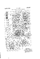
- FIG. 1A conventionally illustrating the dispatchers ofiice equipment and Fig. 1B showing conventionally the wayside equipment of one way-station together with part of the wayside equipment of another way station, and to Fig. 2 which shows a portion of Fig. 1A on an enlarged scale.
- a passing siding PS of a single track railway system which in practice has a large number of passing sidings of the type shown.
- This passing siding is equipped with a starting signal 2, a dwarf starting signal 2, an entering main signal 1, and a take siding signal P, at the east end thereof.
- the track switch of said passing siding PS is controlled by switch machine SM, this track switch being provided with the usual detector track circuit including the track relay TR and the track battery 4.
- the switch machine SM as shown is controlled by the switch machine relay SMR as conventionally shown by a dotted line, this switch machine relay SMR being 113 of the drawings,
- a miniature reproduction 01 the railway system to which the present invention is applied, of which the miniature passing siding ps only has been shown (see Fig. 1A).
- This miniature passing siding is has associated therewith an indicating lamp 1 which is controlled through the medium of the synchronous selector system, so as to be illuminated when the detector track relay TR: is de-energized.
- the lever L for control-- ligg the switch machine relay SMR is associated with the east end of the miniature passing siding 10s.
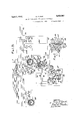
- the synchronous selectors SS", SS and SS are constructed very much alike, and for this reason like parts will be assigned like reference characters.
- Each of these selectors includes a selector shaft 5 which is tensioned in aclock-wise direction through the medium of the pinion 6 driven by the spring operating gear 7 which gear 7 is operated by the coil spring 8 rewindable by the ratchet gear 9 through the medium of stationary pawl 11 and movable pawl 12, which movable pawl is operated by the armature 18 of the winding magnet WM".
- This shaft 5 being tensioned, in a clock-wise direction as just eX- plained, is caused to'be operated by a stepby-step escapement magnet including a palat 14 operated by electro-magnets 15 and 16.
- the shaft 5 also includes a rotating contact arm 20.
- the distinguishing feature of the dispatchers oiiice selector SS from the various way-station selectors, such as selector SS resides in the provision of means for holding these selectors in their normal'zero position, in that the central station selector is held in its normal position by the maintenance of current flowing in the escapement electro-magnet 15, as readily traced from the drawings, whereas the way-station SS is held in its normal Zero position by an electric lock comprising a projecting pin 21 projecting from the shaft 5 hich pin 21 engages the armature 22 of a lock magnet LM All of the various selectors SS", SS SS etc. are operated in synchronism through means 0 line relays L", L L etc.
- the dispatchers office equipment also includes a master relay MR having multiple contacts 25 and 26, which are held in the last actuated position by suitable stick means, such as permanent magnets 27 and 28, and includes oppositively disposed electro-magnets 29 and 38.
- suitable stick means such as permanent magnets 27 and 28, and includes oppositively disposed electro-magnets 29 and 38.
- the starting relays S and S have been provided in the dispatchers ofiice.
- the indicating lamp I in the dispatchers oflice is controlled from the track relay TB at the second way-station through the medium of indicating relays IR and IE
- the relays L, M, N, and 0 have been provided. 7
- battery power supply sources 10 and 80 have mid-points connected to a common wire C, so that their respective sections 'give positive or negative potentials in respect to said common wire 0. Also, battery 30 gives a positive potential in respect to said common wire G. Hence,'circuits will be traced from the positive or negative terminals of the battery source involved, through the various contacts and relay mechanisms to the common wire C only.
- the escapement magnet 15 in the. dispatchers f office is normally energized through a circuit beginning at the positive terminal of the battery 30, wire 10, winding of the electro-magnet 15, wire 17 contact 18 of the line relay L to the common wire 0.
- the electro-magnet 15 at the second way-station is normally energized through a circuit beginning at the positive terminal of the battery-31, contact 32 of the line relay L wire 33, winding of the magnet 15 wires 84, 35, 36, and 37, to the negative terminal of battery 31.
- the line relays L", L and L are energized with negative potential through a circuit traced as follows 2* from the negative terminal of battery 80, through contact 25 in a left hand position, wire 81, relay L", stepping wire 140 to the first way-station, relay L stepping Wire 142 to the second way-station, relay L stepping wire 143, to the common wire C.
- De-energization of this circuit for magnet VIM" etlects re-winding of the clock-work mechanism of the dispatchers oflice selector SS".
- the starting relay S being slow-dropping, completes the following circuit for operating the master relay MR to its right hand position :-from the positive terminal of battery 80, through wires 10 and 59, front contact 58 of relay S wires 60 and 63, back contact 6st of the relay S wires and 66, operating magnet 38 of the master relay MR, Wire 67, checking wire 68, contact 71 of the line relay L in its left hand position, wires 69 and 70, contact arm 20 of the synchronous selector SS checking wire 72, contact 73 of the line relay L in a left hand position, wires 74- and 7 5, arm 20 of the synchronous selector SS checking wire 7 6, to common Wire C.
- this checking circuit includes contacts of all the synchronous selectors, so that the synchronous selectors and line relays at all points must be in corresponding positions, the contact 25 and 26 of the master relay MR operate to their right hand positions, thereby operating the line relays L", and L to their right hand positions, through a circuit traced as follows :-from the positive terminal oi the battery 80, through contact 25 of the master relay MR being in a right hand position, wire 81, through the stepping circuit including the relays L L and L in series as heretofore traced, to the common Wire C.
- the energizing circuit for the magnet 38 of the master relay MB is opened at the checking circuit contacts.
- the circuit for the starting relay S is broken at the segment 49 of the selector SS with the arm 20 now at the first step position which allows the contacts of the slow releasing relay S to drop away, effecting the energization of the relay S I It will be noted here, that the release period of the relay S is greater than the time required for any, or all of the Way-stations to complete the first step.
- the checking circuit contacts will be closed completing a circuit for the magnet 29 of relay MR, as arm 20 of selector SS is in the first step position, before the contacts of the relay S shall have dropped away, so that the magnets 29 and 38 of relay MR are both energized at once.
- the contacts 25 and 26 are in a right hand position, they remain in that position until the magnet 38 is de-energized by the energization of the relay S
- the contacts of the line relays L", L and L remain in right hand positions, until said relays S and S assume proper positions and all the waystation selectors have responded to the first step.
- the energy applied to the magnets 16, 16 and 16 will be of such duration that the pawls 14 and 14 will be energized to an extreme left hand position which closes contacts for energizing the lock magnets LM and LM
- This first impulse being of a rather long duration, causes the lock magnet LM to be energized through the following circuit :-from the positive terminal of the battery 31, (see Fig. 113), through wires 83 and 84, winding of the magnet Ll/ wire 85, contacts 86-87 being slow releasing as these contacts close only after the escapem-ent magnet 16 is energized for a longer period of time than the usual stepping period, wires 88, 36 and 37, to the negative terminal of the battery 31.
- This circuit which is the energization circuit for magnet 29 of relay MR, may be traced as follows :from the posltlye terminal of battery 30, through wire 10, slip ring 96 of the selector SS, contact 97, w re 98, magnet 29 of the master relay MR, wire 99 through the checking circuit heretofore traced, to common wire C.
- the energization and operation of the master relay MR is in response to an energizing circuit which includes the checking circuit, including contact 71 and 73 of line relays L and L and that as soon as any one of the way-station devices fails to take its step, when it should, this checking circuit is opened, and the entire apparatus stops at that particular point in the cycle of operation of the synchronous selector system. From this it appears, that any derangement of parts of the stepping mechanism or circuits associated therewith will effect stopping of the system and apprize the dispatcher of the failure. Since some of these failures may be of little importance, the dispatcher may, if he Wishes, close his cut-out switch CO to shunt the checking circuit heretofore mentioned and allow the apparatus to run without the check afforded by this checking circuit.
- step-by-step operation can, however, only continue, until the arm 20 of the dispatchers selector SS reaches its zero position, for, as soon as that occurs, this arm 20 assumes a position in the gap cut in the slip ring 96, so that the master relay MB is unable to receive current in the manner heretofore explained. If, however, the track relay TR is still in its deenergized position, the starting relay S will be energized after a short time, thus releasing the apparatus and allowing it to run through anothercycle of operation.
- the selector SS connects the message wire directly to the common wire :from the positive terminal of the battery 40, through wires 42, 43 and-101, upper winding of the indicating relay 1R wire 102, back contact 103 of the relay N, wire 104, to the 10th contact of the inner contact ring of the selector mechanism SS", slip ring 105, wire 106, contact 26 of the master relay MR assuming its right hand position, wire 107, contact 108 of the relay LR assuming its left hand position, While the current is building up in its coils for causing its contacts to move to the right effecting the selector SS to take the next step, to the message wire 141, wires 51 and 109, back contact 110 of the track relay TR wire 111, contacts 112 and 113, wire 114, contacts 115 and 116, wire 117, 10th contact of
- the circuit just traced causes energization of the indicating relay IE and with its contact 120 once up, a stick circuit is closed which holds this relay 1R energized through the following circuit, and also picks up the indicating relay 1R :-from the positive terminal of battery 30, through wire 10, upper winding of the indicating relay IR", wire 122, lower winding of the relay 1R wire 123, front contact 120 of the relay IE wires 124 and 125, contact 126 of the relay E, to the common wire C.
- relay 1R With the relay 1R once energized, its front contact 127 closes a stick circuit for this relay through the following circuit :-from the positive terminal of battery 30, through wires 10 and 128, lower wind ing of the relay 1R wire 129, front contact 127 of the relay IE wires 130 and 131, contact 132, of the relay E, to the common Wire C.
- Energization of the relay 1R applies current to the indicating lamp I through the following circuit :-from the positive terminal of battery 30, through wire 10, indicating lamp 1 wire 133, front contact 134, wire 135, to the common wire O.
- the indicating lamp I is thus illuminated in response to dropping of the track relay TR.
- the relay IR also serves another purpose, by providing a contact 146, which insures that the system shall be initiated continually, after the system has been initiated due to the de-energization of a track relay governing an OS channel, so long as an OS channel'carries an indication that there is a train present on any OS-ing track section, and also provides that the system shall operate for two cycles after said OS indication ceases to be transmitted to the dispatchers office.
- the advantage of this resides in the fact, that there is no time lost in receiving the initiating impulse from the way station, thus the synchronous selectors operate through successive cycles more rapidly while the system is indicating the presence of a train upon an OS-ing track section.
- This initiating circuit as accomplished by the OS indicating relay IE is traced as follows :from the positive terminal of battery 40, to wires 42, 43, 44, 45, 46 and 47, relay S wire 48, wire 145, contact arm 20, contact 144, wires 148 and 147, front contract 146, to the common wire O.
- the system is initiated from the way station, when a train first enters an OS track section, after which the system is initiated at the end of each cycle through initiating circuit including the contact 146 of relay 1B for each successive cycle, until the second cycle after the train leaves said OS-ing track section.
- the control for the relay E is accomplished during the last two steps taken by the synchronous selector SS by means of the slip ring segment 136, contacts 137 and 138, and the bridging member 49 of the arm 20.
- the circuit through contact 132 of the relay E is opened by armature A moving to the left by energization of the upper winding of the relay E, when the arm 20 of the synchronous selector SS is at the next to the last step,
- Movement of a lever in the dispatchers office not only initiates the synchronous selector system, but also causes it to operate in steplike fashion at the normal rate, until it gets to the particular channel over which the control indication is to be transmitted in accordance to the new position of a particular lever, at which channel it will hesitate long enough to cause a supplemental and distinctive channel circuit to be completed.
- relays IE and IE in the same manner as indicating relays 1B and 1R were heretofore stuck up, and the relay F will drop at the end of the first cycle of the selector SS and the relay G will be dropped at the end of the second cycle in exactly the same manner as the relays IE and IE It will be noted that with the relay L picked up, the contact 164 of relay L connects the point 165, located at the 10th step of the selector SS", to thernext adjacent point 166, instead of the second adjacent point 167, from which it will appear, that the selector SS comes to a stop as soon as it hits the 10th position.
- the relay G has front contact 149, which is connected. in multiple with the contact 146 of relay 1R
- the energization of relay G- accomplished initiation by energizing the a relay S through a circuit heretofore traced for the initiation of the system at the dispatchers office for receiving OS indica-
- the energization of relay S starts'the selectors SS SS and SS to operate in synchronism as heretofore explained.
- Relays L, F, and G now assume their energized positions and the selector SS is assumed to be stepping along somewhere between the zero and the tenth position. As soon as the contactarm 20 reaches the 10th position, synchronism therewith, the various selectors are stopped, because the contact 165 at the tenth position, doesnot shift the energy from the winding 29 to the winding 30 as otherwise would be the case.
- the bridging member 180 of the contact arm v20 connects the ring 181 with the contact 182, thereby completing the following circuit for the relay M :from the positive terminal of the battery 80, through wire 10, winding of the relay M, wire 183, back contact 184 of the relay N, wire .185, front contact 186 of the relay L, wire 187, contacts 182 and 180, slip ring 181, to the common wire C. WVith this circuit completed the relay M is energized which picks up the relay N through the following circuit z-from the positive terminal of the battery 30, wire 10, winding of the relay N, wire 190, front contact 191 of the relay M, wire 192, to the common wire C.
- the last transitory step in the operation known as automatic hesitation resides in the picking up of relay N. It should be noted that picking up of relay N also opens the channel circuit for the indicating relay IR at the back contact 103, and brakes the energizing circuit for the relay M at the contact 18st. As the relay M is slow-dropping, it assumes its de-energized position after a short time, at which time the relay 0 is picked up through the following circuit :-from the pos itive terminal of battery 30, through wire 10, winding of the relay 0, wire 208, front contact 209 of the relay N, wire 210, back con tact 211 of the relay M, wire 212, to the common wire Q.
- the relay 0 assumes it energized position the stick circuit for the relay L is broken, causing dropping oi? the relay L, which in turn causes the drop 'iing of contact 16% thereof, causing the winding 38 ot the master relay MR to be connected to the contact point 165 oi the selector SS", thereby causing the selector S3" to again he stepped along in its normal way, until it has reached its zero position.
- the de-energization of the relay M opens the energizing circuit of the relay N, which drops away opening the energizing circuit of the relay 0.
- y F is Clo-energized at the last step of the first cycle and relay G de-energized at the second.
- a synchronous selector system for dispatching the movement of trains including, a central ofiice equipment, namely the dispatchers office equipment, and a plurality of way station selectors, in which the particular selectors contain a certain number of positions, for example, thirty contact positions, but wherein as a matter of fact, sixty distinctive message channels are available, half of these meschannels being made available by the principle of automatic hesitation.
- the relays L, M, N and 0 may be omitted, and the distinctive message channel made available by manual hesitation, residing in holding the various selectors stopped at a particular point in their cycle of operation, by the normal operation of the lever L or any other lever of the system used to transmit a control impulse over a distinctive channel made available by operation of the slow-acting inertia members 194 or 195 of a way station se lector.
- a synchronous selector system in which a checking circuit is included to bring the apparatus to a stop in the event any one of the way station selectors failing to remain in synchronism with the other selectors, it is desired to be understood that this feature can be entirely omitted, if desired.
- a train dispatching system of the synchronous selector type comprising, a dispatchers oilice, a plurality of way stations, synchronous selector means at said dispatchers OfilCG and at each of said way stations, a plurality of circuit branches for each of said selectors, operating means for operating said selectors in synchronism to causing sequential closure of corresponding circuit branches of said selectors in synchronisni, said operating means operating said selectors step by step at a predetermined rate, and supplemental. means for causing certain steps in the operation of said synchronous selectors to be taken at a predetermined slower rate.
- A. train dispatching system of the synchronous selector type comprising, a dispatchers oilice, a plurality of way stations, synchronous selector means at said dispatchers ofiice and at each of said way stations, a plurality of circuit branches for each of said hesitate at a particular selectors, operating means for operating said selectors in synchronism to causing sequential closure of corresponding circuit branches of said selectors in synchronism, said operating means operating said selectors step by step at a predetermined rate, and certain of said branch circuits being divided into two subbranch circuits, supplemental means for causing certain steps in the operation of said synchronous selectors to at times be taken at a slower rate, and means for selecting a particular one of the two sub-branch circuits when the step during which the corresponding branch circuit is closed is a step of slow rate.
- a train dispatching system of the synchronous selector type comprising, a dispatchers ofiice, a plurality of way stations, synchronous select-or means at said dispatchers ofiice and at each of said way stations, a plurality of circuit branches for each of said selectors, operating means for operating said selectors in synchronism to cause sequential closure of corresponding circuit branches of said selectors in synchronism, said operating means operating said selectors step by step at a predetermined rate; a slow acting electro-responsive device which assumes one position if the synchronous selectors are stepped at said predetermined rate and assumes another position if the synchronous selectors step for sub-dividing the branch circuit closed at such particular step into two sub-branch circuits one of which is selected it said device assumes one position and the other of which is selected it said device assumes the other position; means for controlling traflic controlling devices distinctively over said synchronous se lectors to hesitate at a particular step during their operation and step at a slower than said predetermined rate.
- a train dispatching system of the synchronous selector type comprising, a dispatchers office, a plurality of way stations, synchronous selector means at said dispatchers office and at each of said way stat-ions, a plurality of circuit branches for each of said selectors, operating means for operating said selectors in synchronism to cause sequential closure of corresponding circuit branches of said selectors in synchronism, said operating means operating said selectors step by step at a predetermined rate; a slow acting relay which assumes one position if the synchronous selectors are stepped at said predetermined rate and assumes another position if the synchronous selectors hesitate at a particular step for sub-dividing the branch circuit closed at such particular step into two sub-branch circuits one of which is selected it said device assumes one position and the other of which is selected if said device assumes the other position; means for controlling trafiic controlling devices distinctively over said p... Oil
- sub-branch circuit and means for at times causing said synchronous selectors to hesitate at a particular step during their operation and step at a slower than said predetermined rate.
- a train dispatching system of the synchronous selector type comprising, a dispatcher's oliice, a plurality of Way stations, synchronous selector means at said dispatchers oilicc and at each of said Way stations, a plurality oi. circuit branches for each of said selectors, operating means for operating said selectors in synchronism to cause sequential closure ot correspond ng c rcuit branches oi" said selectors in synchronism, said operating 11lti:l" on on said selectors step by step at a preilt ed rate; a slow acting electro-res1')onsive device which assumes one position if the synchronous selectors are stepped at said predetermined rate and assumes an other position if the synchronous selectors hesitate at a particular step for sub-dividing the branch circuit closed at such particular step into two si'ib-branch circuits one of which is selected it said device assumes one position and the other of which isselected ii 3 iid device assumes the
- a synchronous selector train dispatching system the combination with a dispatchei-s oilice and a plurality of way stations, of a synchronous selector at said oiiice and at each of said way stations, a plurality of message circuits each including the same line wire rendered available sequentially through the medium of said synchronous selectors, a lever in the dispatchefis office having contacts included in one of said message circuits, a track relay at one of said way stations having a contact included in one of said message circuits, means for causing said synchronous selectors to be initiated into operation and be operated in synchronism through several cycles of operation each time said lever is 0pe *uted, means for causing said synchronous selectors to be operated in synchronism so long as said track relay is deenergized and for at least one complete cycle of operation after said track relay is again energized, and an indicator and a tratlic controlling device con trolled by said track relay and said lever respectively over said message circuits.
- a synchronous selector of at said office and at each of said way stations a plurality of message circuitseachincludingthe same line Wire rendered available sequentially through the medium of said synchronous selectors, a line circuit including in series a plurality of line relays for controlling said synchronous lselectors step by step, traiiic controlling devices controlled over said message circuits, and checking means including a checking circuit for preventing operationof said line relays to cause said synchronous selectors to be operated to the next step unless all of said selectors have/taken their next preceding step.
- a dispatchers otliceand a plurality of way stations, of a synchronous selector at said oflice and at each of said way stations, a plurality ofmessage circuits each including the same line Wire rendered availablesequentially through the medium of said synchronous selectors, a line circuit including in series a plurality of line relays for controlling said synchronous selectors step by step, trailic controlling devices controlled over said message circuits, and checking means including a checking circuit for preventing operation of said line relays to cause said synchronous selectors to be operated to the next step unless all of said selectors assume a position in correspondence with their respective line relays.
- a synchronous selector train dispatching system With a dispatchers oitice and a plurality of way stations, of a synchronous selector at said otlice and at each of said Way stations, a plurality of message circuits each including the same line wire rendered available sequentially through the medium of said synchronous selectors, a line circuit including in series a plurality of line relays for controlling said synchronous selectors step by step, tra'fiic controlling devices controlled over said message circuits, checking means including a checking circuit for preventing operation of said line relays to cause said synchronous selectors to be operated to the next step unless all of said selectors have taken their next preceding step, and manually operable means for rendering said checking means ineffective.
- a synchronous selector train dispatching system the combination with a dispatchers oflice and a plurality of Way stations, of a synchronous selector at said oflice and at each of said way stations, a plurality of message circuits each including the same line Wire rendered available sequentially through the. medium of said synchronous selectors, a line circuit including in series a plurality of line relays for controlling said synchronous selectors step by step, trafiic controlling devices controlled over said message circuits, checking means including a check ing circuit for preventing operation of said line relays to cause said synchronous selectors to be operated to the next step unless all of said selectors assume a position in correspondence with their respectively line relays, and
- step-by-step apparatus located at each of said way stations and at said central oflice for controlling traffic controlling devices at said way stations in accordance with the positions of levers in said 715 central office, means for operating said stepby-step devices in synchronism, checking means for preventing further operation of all of said step-by-step devices if one of said 7 devices fails to take a step when it should,
- the plurality of circuit branches include distinctive circuit branches which are controlled by the operation of the supplemental means to establish such a distinctive circuit branch at each of the selector means for each of said certain steps.
Landscapes
- Engineering & Computer Science (AREA)
- Mechanical Engineering (AREA)
- Selective Calling Equipment (AREA)
Description
April 5, 1932. R. PLANK TRAIN DISPATGHING SYST Filed April 25, 1929 EM FOR RAILROADS 2 Sheets-Sheet l VENTO 753 7%m BY Z ATTORbiEY MMM April 5, 1932. R. PLANK TRAIN DISPATCHING SYSTEM FOR RAILROADS 2 Sheets- Sheet 2 Filed April 25, 1929 BY %i R. 3 an w a? 03 3 H 92 m3 mm. a I: u r
MAME
w ATTORNEY Patented Apr. 5, 1932 UNITED STATES PATENT OFFICE GENERAL RAILWAY SIGNAL YORK TRAIN DISPATCHING SYSTEM FOR RAILROADS Application filed April 25,
This invention relates to train dispatching systems, and more particularly to a synchronous selector system for controlling the switch machine and signals of such a dispatching system.
In dispatching the movement of trains, it is necessary or desirable to control a large number of signals and switch machines over a comparatively few wires by reason of the fact, that the switch machine and signals are located many miles from the dispatchers office. Also, in a system of this kind, in order for the dispatcher to keep in touch with the apparatus along the railway track, it is desirable to transmit OS indications to inform the dispatcher of track circuit occupancy, the indicating condition of signals, and the positions of switch machines. Since numerous of these track way conditions may change simultaneously, it is difficult to use code responsive mechanisms for transmitting these OS indications to the dispatchers oflice, although a synchronous selector system, in which a large number of successively available message channels are obtainable, appears to be peculiarly adaptable. Also, in a system of the synchronous selector type, it is desirable to have the dispatcher informed at all times as to the operativeness of the synchronous selectors, especially is it desirable to inform the dispatcher, if one of the waystation selectors should get out of step or synchronism with the selector located in the dispatchers office.
In accordance with the above and other important considerations, the present invention contemplates the use of a synchronous selector system, in which it is necessary for each of the various selectors to take each step, the selector being of the step-by-step type, in order to keep the mechanism in operation, so that the failure of any way-station selector is manifested in the dispatchers oflice by stopping of the entire system. It is further proposed in accordance with the present in vention to have cut-out means in the dispatchers office, whereby, if the apparatus has come to a stop because one of the way-station selectors has failed to respond, the dispatcher may cut out the checking mechanism and 1929. Serial No. 358,076.
again allow such apparatus that is in working condition, to operate in response to the closing of said cut-out switch.
As another object of the present invention, it is proposed to double the capacity of the synchronous selector system by making distinctive channel circuits available at a particular point in the cycle of operation of the synchronous selectors by automatic hesitation, which resides in the provision of means for automatically causing the synchronous selectors to stop at a particular point in their cycle for a suflicient period of time to allow a slowshifting contact to move and establish a distinctive message channel.
Other objects, purposes, and characteristic features of the present invention will be in part obvious from the accompanying drawings and will in part appear from the accompanying detail description.
In describing the invention in detail reference will be made to Figs. 1A and 1B, which if laid end to end constitute one embodiment of the present invention, Fig. 1A conventionally illustrating the dispatchers ofiice equipment and Fig. 1B showing conventionally the wayside equipment of one way-station together with part of the wayside equipment of another way station, and to Fig. 2 which shows a portion of Fig. 1A on an enlarged scale.
-Referring first to Fig. wherein there has been shown a passing siding PS of a single track railway system which in practice has a large number of passing sidings of the type shown. This passing siding is equipped with a starting signal 2, a dwarf starting signal 2, an entering main signal 1, and a take siding signal P, at the east end thereof. The track switch of said passing siding PS, is controlled by switch machine SM, this track switch being provided with the usual detector track circuit including the track relay TR and the track battery 4. The switch machine SM as shown is controlled by the switch machine relay SMR as conventionally shown by a dotted line, this switch machine relay SMR being 113 of the drawings,
controlled through the medium of a synchronous selector system in a manner as more clearly pointed out hereinafter.
In the dispatchers office is a miniature reproduction 01": the railway system to which the present invention is applied, of which the miniature passing siding ps only has been shown (see Fig. 1A). This miniature passing siding is has associated therewith an indicating lamp 1 which is controlled through the medium of the synchronous selector system, so as to be illuminated when the detector track relay TR: is de-energized. Also, associated with the east end of the miniature passing siding 10s is the lever L for control-- ligg the switch machine relay SMR (see Fig. 1
The synchronous selectors SS", SS and SS are constructed very much alike, and for this reason like parts will be assigned like reference characters. Each of these selectors includes a selector shaft 5 which is tensioned in aclock-wise direction through the medium of the pinion 6 driven by the spring operating gear 7 which gear 7 is operated by the coil spring 8 rewindable by the ratchet gear 9 through the medium of stationary pawl 11 and movable pawl 12, which movable pawl is operated by the armature 18 of the winding magnet WM". This shaft 5 being tensioned, in a clock-wise direction as just eX- plained, is caused to'be operated by a stepby-step escapement magnet including a palat 14 operated by electro- magnets 15 and 16. The shaft 5 also includes a rotating contact arm 20. The distinguishing feature of the dispatchers oiiice selector SS from the various way-station selectors, such as selector SS resides in the provision of means for holding these selectors in their normal'zero position, in that the central station selector is held in its normal position by the maintenance of current flowing in the escapement electro-magnet 15, as readily traced from the drawings, whereas the way-station SS is held in its normal Zero position by an electric lock comprising a projecting pin 21 projecting from the shaft 5 hich pin 21 engages the armature 22 of a lock magnet LM All of the various selectors SS", SS SS etc. are operated in synchronism through means 0 line relays L", L L etc. all connected in series. The dispatchers office equipment also includes a master relay MR having multiple contacts 25 and 26, which are held in the last actuated position by suitable stick means, such as permanent magnets 27 and 28, and includes oppositively disposed electro-magnets 29 and 38. In order to give a long starting impulse for winding the various clockwork mechanisms of the synchronous selectors, and for synchronizing the various synchronous selectors, the starting relays S and S have been provided in the dispatchers ofiice.
It is considered expedient to normally hold the synchronous selectors at rest, and to assure that they will carry out a particular control of indication function, it is proposed to run these selectors through at least two cycles of operation each time that the system is initiated, and the relays E, F, and G in the dispatchers office have been provided for this purpose. The indicating lamp I in the dispatchers oflice is controlled from the track relay TB at the second way-station through the medium of indicating relays IR and IE In order to cause the synchronous selector to he stepped along at the usual step-by-step rate, and to hesitateor remain at a particular indicating position for an appreciable period of time for the purpose of setting up an additional message channel by the principle 'of automatic hesitation heretofore mentioned, the relays L, M, N, and 0, have been provided. 7
It will be noted here, that battery power supply sources 10 and 80 have mid-points connected to a common wire C, so that their respective sections 'give positive or negative potentials in respect to said common wire 0. Also, battery 30 gives a positive potential in respect to said common wire G. Hence,'circuits will be traced from the positive or negative terminals of the battery source involved, through the various contacts and relay mechanisms to the common wire C only.
Having now pointed out in a general way, what the functions of the various devices are, and having co-ordinated the way side equipment with the dispatchers ofiic-e equipment, it is believed expedient to consider the operation of the system, in order to get a clear understanding of its operating features and characteristics.
OPERATION N ormal conditions.-Let us first consider the normally closed circuits in the system, and thereafter note when these circuits are broken and when other circuits are completed as the sequential steps in the operation are taken up. i 7
Attention is directed to the fact, that the escapement magnet 15 in the. dispatchers f office is normally energized through a circuit beginning at the positive terminal of the battery 30, wire 10, winding of the electro-magnet 15, wire 17 contact 18 of the line relay L to the common wire 0. Also, it should be noted thatthe electro-magnet 15 at the second way-station is normally energized through a circuit beginning at the positive terminal of the battery-31, contact 32 of the line relay L wire 33, winding of the magnet 15 wires 84, 35, 36, and 37, to the negative terminal of battery 31. Attention is further directed to the fact, hat even through this circuit just traced for electro magnet 15 were broken, the shaft .5 would notbe' free to rotate in response to the torque of its main spring'8 cuit containing the the circuit for the winding magnet because the stop armature 22 of the lock magnet LM prevents rotation of this shaft 5 It should also be noted, that a starting relay S is normally energized by a circuit beginning at the positive terminal of the battery 80, wires 10 and 59, back contact 58 of the starting relay S wire 17 to the relay S to common wire C. The line relays L", L and L are energized with negative potential through a circuit traced as follows 2* from the negative terminal of battery 80, through contact 25 in a left hand position, wire 81, relay L", stepping wire 140 to the first way-station, relay L stepping Wire 142 to the second way-station, relay L stepping wire 143, to the common wire C.
Transmission of O. S. indications-Having now traced all of the normally closed c1rcuits, let us consider the operation of the system when it is initiated from a way-station. In this connection it may be pointed out that if the apparatus is initiated from a waystation, due to the de-energization ot a track relay the apparatus remains in operation so long as the track relay is de-energized but that in the event the system is initiated from the dispatchers office, as by the move ment of one of the control levers, the synchronous selector system operates only through two complete cycles of operation as it is again brought to a stop.
Let us now assume, that a train is moving from left to right through the passing siding PS and is occupying the detector track cirtrack relay TR thus causing de-energization of this track relay TR? Dropping of the contact 11 of this track relay TR connects the message circuit to the common wire and in response thereto efl'ects energization of the starting relay S in the dispatchefs office through the following circuits :from the positive terminal of the battery 40, through wires 42, 43, 44, 45, 46, and 17, winding of the starting relay S wire 8, contact 419 on the selector arm 20, Wire 50, through the message wire to the second waystation, wires 51 and 52, back contact 41 of the track relay TR wire 58, bridging memher 55 of the selector arm 20 slip ring 55, wire 56, to the common wire The starting relay S will, a short time after completion of this circuit, raise its contact 58 to break the energizing circuit for the starting relay S heretofore traced, and completing WM", which may be traced as follows z-from the positive terminal of battery 30, through wires 10, and 59, front contact 58, of the relay S wires 60 and 61, winding of the magnet WM", to common wire G. De-energization of this circuit for magnet VIM" etlects re-winding of the clock-work mechanism of the dispatchers oflice selector SS". After a short time, the starting relay S being slow-dropping, completes the following circuit for operating the master relay MR to its right hand position :-from the positive terminal of battery 80, through wires 10 and 59, front contact 58 of relay S wires 60 and 63, back contact 6st of the relay S wires and 66, operating magnet 38 of the master relay MR, Wire 67, checking wire 68, contact 71 of the line relay L in its left hand position, wires 69 and 70, contact arm 20 of the synchronous selector SS checking wire 72, contact 73 of the line relay L in a left hand position, wires 74- and 7 5, arm 20 of the synchronous selector SS checking wire 7 6, to common Wire C. With this circuit completed it being noted that this checking circuit includes contacts of all the synchronous selectors, so that the synchronous selectors and line relays at all points must be in corresponding positions, the contact 25 and 26 of the master relay MR operate to their right hand positions, thereby operating the line relays L", and L to their right hand positions, through a circuit traced as follows :-from the positive terminal oi the battery 80, through contact 25 of the master relay MR being in a right hand position, wire 81, through the stepping circuit including the relays L L and L in series as heretofore traced, to the common Wire C. llacing positive potential on the stepping circuit, causes the contacts of the line relays U, L and L to assume their right hand positions, thereby de-energizing the electro- magnets 15, 15 and 15 and energizing the electro- magnets 16, 16 and 16 Hence, the pawls 1 1, 14 and 14 move to the left, allowing the selector SS to take one step, and allowing the selectors SS and SS to take one step after their lock magnets LM and LM have been energized.
As soon as the contacts of the line relays L", L and L have assumed their right hand positions, the energizing circuit for the magnet 38 of the master relay MB is opened at the checking circuit contacts. The circuit for the starting relay S is broken at the segment 49 of the selector SS with the arm 20 now at the first step position which allows the contacts of the slow releasing relay S to drop away, effecting the energization of the relay S I It will be noted here, that the release period of the relay S is greater than the time required for any, or all of the Way-stations to complete the first step. Thus, the checking circuit contacts will be closed completing a circuit for the magnet 29 of relay MR, as arm 20 of selector SS is in the first step position, before the contacts of the relay S shall have dropped away, so that the magnets 29 and 38 of relay MR are both energized at once. However, as the contacts 25 and 26 are in a right hand position, they remain in that position until the magnet 38 is de-energized by the energization of the relay S During the time that the contacts ofrelay relay S are being S are dropping away and the contacts of de-energized, the contacts of the line relays L", L and L remain in right hand positions, until said relays S and S assume proper positions and all the waystation selectors have responded to the first step. Hence, the energy applied to the magnets 16, 16 and 16 will be of such duration that the pawls 14 and 14 will be energized to an extreme left hand position which closes contacts for energizing the lock magnets LM and LM This first impulse, being of a rather long duration, causes the lock magnet LM to be energized through the following circuit :-from the positive terminal of the battery 31, (see Fig. 113), through wires 83 and 84, winding of the magnet Ll/ wire 85, contacts 86-87 being slow releasing as these contacts close only after the escapem-ent magnet 16 is energized for a longer period of time than the usual stepping period, wires 88, 36 and 37, to the negative terminal of the battery 31. The completion of this c1r-cu1t raises the lock armature 22 and releases the lock pin 21. Also, operation of the armature 22 closes the contacts 89-90 for closing the re-winding circuit traced as follows :-from the positive terminal of battery 81, through wires 83 and 91, contacts 89 90, wire 92, winding of magnet M wires 93 and 37, to the negative terminal of battery 31. Thus the re-winding of the synchronous selector. SS is accomplished during the time of deenergization of the starting relay S and the re-energization of the starting relay S It should be noted, that in the mean time the arm 20 of the selector SS having been operated to the first step position as formerly stated, has closed the following circuit which by itself cannot cause operating of selector SS until another circuit, as presently pointed out is broken. This circuit, which is the energization circuit for magnet 29 of relay MR, may be traced as follows :from the posltlye terminal of battery 30, through wire 10, slip ring 96 of the selector SS, contact 97, w re 98, magnet 29 of the master relay MR, wire 99 through the checking circuit heretofore traced, to common wire C. The magnet 29 1s thus energized, but since the contacts 25 and 26 were assuming the right hand position at the time, and since the magnet 38 is still energized, the master relay MB is not moved to the right, until the magnet 38 is de-energized, which occurs immediately upon picking up of the starting relay S and we may assume that, that has now taken place, and that the main relay MR is again operated to the left which operates the contacts of the line relays L", L and L to the left. Each of the way-station selectors as well as the disp atchers office selector, now take another step in response to their respective line relays. It will he noted that each time the selector SS has taken anew step in response to the position assumed by started from rest in response the line relay LR", this selector effects operation of the contacts of the master relay MB to the opposite position, which master relay in turn causes the operation of the contacts of the line relay LR". Also, the de-energization I of relay S? opens the circuit for the magnet Wt 1, so that its armature drops away ready to effect thewinding of spring 8 at the beginning of the next cycle.
In this connection it should however be noted that the energization and operation of the master relay MR is in response to an energizing circuit which includes the checking circuit, including contact 71 and 73 of line relays L and L and that as soon as any one of the way-station devices fails to take its step, when it should, this checking circuit is opened, and the entire apparatus stops at that particular point in the cycle of operation of the synchronous selector system. From this it appears, that any derangement of parts of the stepping mechanism or circuits associated therewith will effect stopping of the system and apprize the dispatcher of the failure. Since some of these failures may be of little importance, the dispatcher may, if he Wishes, close his cut-out switch CO to shunt the checking circuit heretofore mentioned and allow the apparatus to run without the check afforded by this checking circuit.
As we now understand the apparatus, if once initiated the various synchronous selectors SS SS and SS will be operated stepby-step in synchronism. This step-by-step operation can, however, only continue, until the arm 20 of the dispatchers selector SS reaches its zero position, for, as soon as that occurs, this arm 20 assumes a position in the gap cut in the slip ring 96, so that the master relay MB is unable to receive current in the manner heretofore explained. If, however, the track relay TR is still in its deenergized position, the starting relay S will be energized after a short time, thus releasing the apparatus and allowing it to run through anothercycle of operation.
Having now explained how the system is to dropping of the track relay TR let us see how the fact, that this track relay TR has dropped, is manifested in the dispatchers oflice.
As the arms 20 and 20 are rotated in synchronism when they reach the tenth position, they engage contacts marked 10th and close the following circuit, it being noted that this point in the cycle the selector SS connects the message wire directly to the common wire :from the positive terminal of the battery 40, through wires 42, 43 and-101, upper winding of the indicating relay 1R wire 102, back contact 103 of the relay N, wire 104, to the 10th contact of the inner contact ring of the selector mechanism SS", slip ring 105, wire 106, contact 26 of the master relay MR assuming its right hand position, wire 107, contact 108 of the relay LR assuming its left hand position, While the current is building up in its coils for causing its contacts to move to the right effecting the selector SS to take the next step, to the message wire 141, wires 51 and 109, back contact 110 of the track relay TR wire 111, contacts 112 and 113, wire 114, contacts 115 and 116, wire 117, 10th contact of selector SS segment 54 of the arm 20 slip ring 55, wire 56, to the common wire C. At this point it is desired to point out that the contacts 86, 113, and 116 of the way station selector SS are slowacting and will not be operated from their biased position, unless the escapement palat 14 is operated to the corresponding position for an appreciable period of time. Under the condition assumed, the apparatus was not caused to hesitate on the tenth contact marked 10th so that the switch member 116 is assuming its left position. In other words, these contacts 86, 113 and 116 assume their spring biased positions when the system is synchronously stepped for Q 0. S. indications and are moved to their opposite positions when the system is at rest or hesitates at a particular contact which it does not do for transmission of OS indications. The circuit just traced causes energization of the indicating relay IE and with its contact 120 once up, a stick circuit is closed which holds this relay 1R energized through the following circuit, and also picks up the indicating relay 1R :-from the positive terminal of battery 30, through wire 10, upper winding of the indicating relay IR", wire 122, lower winding of the relay 1R wire 123, front contact 120 of the relay IE wires 124 and 125, contact 126 of the relay E, to the common wire C. With the relay 1R once energized, its front contact 127 closes a stick circuit for this relay through the following circuit :-from the positive terminal of battery 30, through wires 10 and 128, lower wind ing of the relay 1R wire 129, front contact 127 of the relay IE wires 130 and 131, contact 132, of the relay E, to the common Wire C. Energization of the relay 1R applies current to the indicating lamp I through the following circuit :-from the positive terminal of battery 30, through wire 10, indicating lamp 1 wire 133, front contact 134, wire 135, to the common wire O. The indicating lamp I is thus illuminated in response to dropping of the track relay TR.
It may be pointed out that the reason for using two indicating relays IE and IE each of which is stuck up through its ownstick circuit, is to avoid a flickering or a single momentary flashing of the indicating lamp 1 for each cycle of operation. In other Words. these relays IE and 1B are used to hold over, so to speak, the momentary indication transmitted from the track relay TR? This is accomplished in the following Way at the end of the first revolution of the synchronous selector SS the armature A of the relay E is operated to the left and then to the right, thereby first breaking the stick circuit for the relay 1R but since this relay is energized by two entirely different circuits this relay will not be dropped, but upon energization of the relay E toward the right the stick circuit for the lower winding of indicating relay IE is broken thereby causing deenergization of this relay IE At the end of the next revolution of the selector SS the breaking of the stick circuit for the relay IE is effective to dropthe relay IR and ex tinguish the lamp I unless in the mean time another indicationhas come from the track relay TR and has picked up the indicating relay IE in a manner as heretofore explained, in which event the indicating lamp I -is not extinguished. It is thus seen that the indi cating lamp 1 may be maintained illuminated, so long as the track relay TR remains deenergized.
The relay IR also serves another purpose, by providing a contact 146, which insures that the system shall be initiated continually, after the system has been initiated due to the de-energization of a track relay governing an OS channel, so long as an OS channel'carries an indication that there is a train present on any OS-ing track section, and also provides that the system shall operate for two cycles after said OS indication ceases to be transmitted to the dispatchers office. The advantage of this resides in the fact, that there is no time lost in receiving the initiating impulse from the way station, thus the synchronous selectors operate through successive cycles more rapidly while the system is indicating the presence of a train upon an OS-ing track section. This initiating circuit, as accomplished by the OS indicating relay IE is traced as follows :from the positive terminal of battery 40, to wires 42, 43, 44, 45, 46 and 47, relay S wire 48, wire 145, contact arm 20, contact 144, wires 148 and 147, front contract 146, to the common wire O. Thus, the system is initiated from the way station, when a train first enters an OS track section, after which the system is initiated at the end of each cycle through initiating circuit including the contact 146 of relay 1B for each successive cycle, until the second cycle after the train leaves said OS-ing track section.
The control for the relay E is accomplished during the last two steps taken by the synchronous selector SS by means of the slip ring segment 136, contacts 137 and 138, and the bridging member 49 of the arm 20. The circuit through contact 132 of the relay E is opened by armature A moving to the left by energization of the upper winding of the relay E, when the arm 20 of the synchronous selector SS is at the next to the last step,
.winding' of the relay F,
through a circuit being traced as follows from the positive terminal of battery 40, through wires 42, 43 and 44, upper winding of the relay E, wire 213, contact 137, bridging member 49 of the arm 20, slip ring 136, wire 214, to the common wire C. When the arm 20 of the synchronous selector SS is at the last step position before again reaching the starting or zero position, the circuit through the contact 126 of the relay E is opened by the'armature A moving to the right hand position by the energization of the lower winding of relay E through a circuit traced as follows :from the positive terminal of battery 40, through wires 42, 43, 44 and 45, through the lower winding of relay E,wire 215, contact 138, bridging member 49 of the arm 20, slip ring 136, wire 214, to the common wire 0.
Transmission of control inclz'cations. Movement of a lever in the dispatchers office not only initiates the synchronous selector system, but also causes it to operate in steplike fashion at the normal rate, until it gets to the particular channel over which the control indication is to be transmitted in accordance to the new position of a particular lever, at which channel it will hesitate long enough to cause a supplemental and distinctive channel circuit to be completed.
Let us assume that the lever L is moved downwardly with the intent of moving the polar contact of the switch machine relay SMR to its left hand dotted position for the purpose of operating the switch machine SM to the take-siding position. Downward movement of the lever L causes a circuit to be momentarily completed at the time that spring contact 150 engages spring contacts 151 and 152, and this momentarily completed circuit may be traced as follows: from the positive terminal of the battery 40, through wires 42, 153, 154 and 155, contacts 151 150152, wires 156 and 157, winding of the relay L, to the common wire C. The momentary completion of this circuit picks up the contacts of the relay L, closing its stick circuit through front contact 158, with the circuit traced as follows :from positive terminal of the battery 40, through wires 42, 43, 44, 45, 46 and 159, back contact 160 of the relay 0, wire 161, front contact 158 of the relay L, wires 162 and 157, winding of the relay L, to the common wire C. The relay L is thus stuck up through a back contact 160 of the relay 0. Also, picking up of the relay L completes the following circuit for picking up the relays F and (in-from the positive side of the battery 30, wire 10, upper winding of the relay G, wire 170, wires 172 and 17 3, front contact 17 4 of the relay L, to the Common wire C. With these relays F and G once picked up, they will remain energized through stick circults closed through front tions continuously.
contacts 176 and 177, in the same manner as indicating relays 1B and 1R were heretofore stuck up, and the relay F will drop at the end of the first cycle of the selector SS and the relay G will be dropped at the end of the second cycle in exactly the same manner as the relays IE and IE It will be noted that with the relay L picked up, the contact 164 of relay L connects the point 165, located at the 10th step of the selector SS", to thernext adjacent point 166, instead of the second adjacent point 167, from which it will appear, that the selector SS comes to a stop as soon as it hits the 10th position. this being because current is not shifted from the coil 29 of the master relay MR to the coil 38 of this relay MR as would otherwise be the case. This stopping of the selector at a particular point in its cycle of rotation, which stopping will continue for a limited time only as will directly appear, is for convenience called automatic hesitation.
The relay G has front contact 149, which is connected. in multiple with the contact 146 of relay 1R Thus, the energization of relay G- accomplished initiation by energizing the a relay S through a circuit heretofore traced for the initiation of the system at the dispatchers office for receiving OS indica- The energization of relay S starts'the selectors SS SS and SS to operate in synchronism as heretofore explained.
Relays L, F, and G now assume their energized positions and the selector SS is assumed to be stepping along somewhere between the zero and the tenth position. As soon as the contactarm 20 reaches the 10th position, synchronism therewith, the various selectors are stopped, because the contact 165 at the tenth position, doesnot shift the energy from the winding 29 to the winding 30 as otherwise would be the case. With the rotating contact arm 20 in the 10th position, the bridging member 180 of the contact arm v20 connects the ring 181 with the contact 182, thereby completing the following circuit for the relay M :from the positive terminal of the battery 80, through wire 10, winding of the relay M, wire 183, back contact 184 of the relay N, wire .185, front contact 186 of the relay L, wire 187, contacts 182 and 180, slip ring 181, to the common wire C. WVith this circuit completed the relay M is energized which picks up the relay N through the following circuit z-from the positive terminal of the battery 30, wire 10, winding of the relay N, wire 190, front contact 191 of the relay M, wire 192, to the common wire C. Relays M and N being both slow-acting allow the line relays L", L and L to be in their left hand positions for an appreci able period of time, sufiicient to allow the slow-acting inertia member to move the contact 16 from a left hand posi- 194 (see Fig.1B)
ion
tion to the right hand position as shown, so that the tenth contact marked 10th of the selector SS is connected to the relay SMR instead of the back contact 110 of the track relay TIP, as is the use when system is initiated by an OS indication. Vith the relay N now picked up a distinctive channel circuit which is distinctive from the channel circuit heretofore traced over the contacts at the 10th position of the selectors SS" and $S which distinctive channel circuit may be traced as follows :from the negative terminal of the battery lO, wires 1-9, contacts 196 and 197 of the lever L, Wire 5216 and 199, front contact 200 of the relay N, wire 201, front contact 202 of the relay M, wire 203, through the message wire l ll to the second way station (see Fig. 1B), wire 204-, winding of the switch machine relay SMR wire 205, contacts 206 and 116, wire 11?, contact 10th, bridging member 5a, slip ring 55 of the synchronous selector SS wire 56, to the common wire C. The completion of this circuit applies negative potential to the switch machine relay 55MB which results in the energization of its polar contact to a left hand position thus controlling the switch machine 3M to operate the track switch for a take siding position.
By st-l'idying the contact and circuit conncctions of the lever L it is obvious that it the lever L is moved upward, the apparatus will be caused to function in exactly the same mani'ier as ust explained, except that nega tive potential will be applied to the relay tilMlit thus operating it to the right hand position, controlling the switch machine SM to operate the track switch for main line trallic.
The last transitory step in the operation known as automatic hesitation resides in the picking up of relay N. It should be noted that picking up of relay N also opens the channel circuit for the indicating relay IR at the back contact 103, and brakes the energizing circuit for the relay M at the contact 18st. As the relay M is slow-dropping, it assumes its de-energized position after a short time, at which time the relay 0 is picked up through the following circuit :-from the pos itive terminal of battery 30, through wire 10, winding of the relay 0, wire 208, front contact 209 of the relay N, wire 210, back con tact 211 of the relay M, wire 212, to the common wire Q. As soon as, the relay 0 assumes it energized position the stick circuit for the relay L is broken, causing dropping oi? the relay L, which in turn causes the drop 'iing of contact 16% thereof, causing the winding 38 ot the master relay MR to be connected to the contact point 165 oi the selector SS", thereby causing the selector S3" to again he stepped along in its normal way, until it has reached its zero position. The de-energization of the relay M, opens the energizing circuit of the relay N, which drops away opening the energizing circuit of the relay 0. As the rel, y F is Clo-energized at the last step of the first cycle and relay G de-energized at the second. last step of the second cycle as controlled by the contacts 126 and 132 of the re lay E, then the front contact 1 19 is in an energized position, so that when the arm 20 reaches the zero or at rest position the relay S will again be energized and the synchronous selectors SS", SS and SS will again operate through another cycle. 7
As it was assumed, that the system was at rest when the lever L was moved downward, then the control indication was transmitted during the first cycle of operation of the synchronous selector system and the energization of the relay L was cancelled during the first cycle. In other words, the relay L was de energized as soon as the control indication was transmitted during the first cycle while the selector arms were on the 10th position.
Now let us assume, that the system is in synchronous operation picking up OS indications and the arms 20, 20 and 20 have just passed the 10th position, when the lever L is moved to give a control indication. Then the relay L is energized, resulting in the energization of relays F and G, but as the selector arms 20, 20 and 20 come to the last step position before the at rest position the relay F is de-energized as heretofore eX- plained. However, the relay G is still energized, which insures that the control indication desired to be transmitted by the movement of the lever L is transmitted during the second complete cycle after the control lever has been moved. In other words itis impossible to move the lever L or any control lover. at such a time that there shall not be at least one complete cycle after such movement of a control lever.
lt thus seen, that a synchronous selector system has been provided for dispatching the movement of trains including, a central ofiice equipment, namely the dispatchers office equipment, and a plurality of way station selectors, in which the particular selectors contain a certain number of positions, for example, thirty contact positions, but wherein as a matter of fact, sixty distinctive message channels are available, half of these meschannels being made available by the principle of automatic hesitation.
It should be understood that, if desired, the relays L, M, N and 0 may be omitted, and the distinctive message channel made available by manual hesitation, residing in holding the various selectors stopped at a particular point in their cycle of operation, by the normal operation of the lever L or any other lever of the system used to transmit a control impulse over a distinctive channel made available by operation of the slow-acting inertia members 194 or 195 of a way station se lector. Also, having provided a synchronous selector system, in which a checking circuit is included to bring the apparatus to a stop in the event any one of the way station selectors failing to remain in synchronism with the other selectors, it is desired to be understood that this feature can be entirely omitted, if desired.
Attention is directed to the fact, that when a lever such as lever L is operated, the synchronous selector apparatus will operate through two successive cycles after which the system will come to rest, this being accomplished by the provision of the relays F and Gr. It is to be understood that, if desired,
this feature of allowing the synchronous selector mechanism to operate only through two cycles of operation after manual initiation thereof, as by lever L may also be applied in allowing the apparatus to operate through only two successive cycles of operation when the system is started from a way station, as for instance by the dropping of the track relay TR Having thus shown and described one rather complete train dispatching system of the synchronous selector type, it is desired to be understood, that the particular system and circuit arrangement illustrated has been resorted to for the purpose of disclosing the nature of the invention and its underlying principles of operation, and has not been selected for the purpose of disclosing the scope of the invention or the exact construction preferably employed in practicing the same, and that various changes, modifications, and additions may be made to adapt the invention to the particular dispatching problem to which the invention is to be applied, all without departing from the spirit or scope thereof, or the idea of means underlying the same, except as demanded by the scope of the following claims.
What I claim is 1. A train dispatching system of the synchronous selector type comprising, a dispatchers oilice, a plurality of way stations, synchronous selector means at said dispatchers OfilCG and at each of said way stations, a plurality of circuit branches for each of said selectors, operating means for operating said selectors in synchronism to causing sequential closure of corresponding circuit branches of said selectors in synchronisni, said operating means operating said selectors step by step at a predetermined rate, and supplemental. means for causing certain steps in the operation of said synchronous selectors to be taken at a predetermined slower rate.
2, A. train dispatching system of the synchronous selector type comprising, a dispatchers oilice, a plurality of way stations, synchronous selector means at said dispatchers ofiice and at each of said way stations, a plurality of circuit branches for each of said hesitate at a particular selectors, operating means for operating said selectors in synchronism to causing sequential closure of corresponding circuit branches of said selectors in synchronism, said operating means operating said selectors step by step at a predetermined rate, and certain of said branch circuits being divided into two subbranch circuits, supplemental means for causing certain steps in the operation of said synchronous selectors to at times be taken at a slower rate, and means for selecting a particular one of the two sub-branch circuits when the step during which the corresponding branch circuit is closed is a step of slow rate.
3. A train dispatching system of the synchronous selector type comprising, a dispatchers ofiice, a plurality of way stations, synchronous select-or means at said dispatchers ofiice and at each of said way stations, a plurality of circuit branches for each of said selectors, operating means for operating said selectors in synchronism to cause sequential closure of corresponding circuit branches of said selectors in synchronism, said operating means operating said selectors step by step at a predetermined rate; a slow acting electro-responsive device which assumes one position if the synchronous selectors are stepped at said predetermined rate and assumes another position if the synchronous selectors step for sub-dividing the branch circuit closed at such particular step into two sub-branch circuits one of which is selected it said device assumes one position and the other of which is selected it said device assumes the other position; means for controlling traflic controlling devices distinctively over said synchronous se lectors to hesitate at a particular step during their operation and step at a slower than said predetermined rate.
a. A train dispatching system of the synchronous selector type comprising, a dispatchers office, a plurality of way stations, synchronous selector means at said dispatchers office and at each of said way stat-ions, a plurality of circuit branches for each of said selectors, operating means for operating said selectors in synchronism to cause sequential closure of corresponding circuit branches of said selectors in synchronism, said operating means operating said selectors step by step at a predetermined rate; a slow acting relay which assumes one position if the synchronous selectors are stepped at said predetermined rate and assumes another position if the synchronous selectors hesitate at a particular step for sub-dividing the branch circuit closed at such particular step into two sub-branch circuits one of which is selected it said device assumes one position and the other of which is selected if said device assumes the other position; means for controlling trafiic controlling devices distinctively over said p... Oil
sub-branch circuit; and means for at times causing said synchronous selectors to hesitate at a particular step during their operation and step at a slower than said predetermined rate.
5. A train dispatching system of the synchronous selector type comprising, a dispatcher's oliice, a plurality of Way stations, synchronous selector means at said dispatchers oilicc and at each of said Way stations, a plurality oi. circuit branches for each of said selectors, operating means for operating said selectors in synchronism to cause sequential closure ot correspond ng c rcuit branches oi" said selectors in synchronism, said operating 11lti:l" on on said selectors step by step at a preilt ed rate; a slow acting electro-res1')onsive device which assumes one position if the synchronous selectors are stepped at said predetermined rate and assumes an other position if the synchronous selectors hesitate at a particular step for sub-dividing the branch circuit closed at such particular step into two si'ib-branch circuits one of which is selected it said device assumes one position and the other of which isselected ii 3 iid device assumes the other position; means for controlling traiiic controlling devices distinctively over said sub-branch circuits; another relay which it it assumes one position causes said synchronous selectors to stop when they reach said particular step and when it assumes another position allows said synchronous selector to take the next step; and other means for causing said another relav to assume said another position a predetermined time after said synchronous selrctors have taken said particular step.
(i. In a synchronous selector train dispatching system, the combination with a dispatchei-s oilice and a plurality of way stations, of a synchronous selector at said oiiice and at each of said way stations, a plurality of message circuits each including the same line wire rendered available sequentially through the medium of said synchronous selectors, a lever in the dispatchefis office having contacts included in one of said message circuits, a track relay at one of said way stations having a contact included in one of said message circuits, means for causing said synchronous selectors to be initiated into operation and be operated in synchronism through several cycles of operation each time said lever is 0pe *uted, means for causing said synchronous selectors to be operated in synchronism so long as said track relay is deenergized and for at least one complete cycle of operation after said track relay is again energized, and an indicator and a tratlic controlling device con trolled by said track relay and said lever respectively over said message circuits.
7. In a synchronous selector train dispatching system, the combination with a dispatchers oiiice and a plurality of way stations, of
a synchronous selector of at said office and at each of said way stations, a plurality of message circuitseachincludingthe same line Wire rendered available sequentially through the medium of said synchronous selectors, a line circuit including in series a plurality of line relays for controlling said synchronous lselectors step by step, traiiic controlling devices controlled over said message circuits, and checking means including a checking circuit for preventing operationof said line relays to cause said synchronous selectors to be operated to the next step unless all of said selectors have/taken their next preceding step.
8. in a synchronous selectortrain dispatching system, the combination with a dispatchers otliceand a plurality of way stations, of a synchronous selector at said oflice and at each of said way stations,a plurality ofmessage circuits each including the same line Wire rendered availablesequentially through the medium of said synchronous selectors, a line circuit including in series a plurality of line relays for controlling said synchronous selectors step by step, trailic controlling devices controlled over said message circuits, and checking means including a checking circuit for preventing operation of said line relays to cause said synchronous selectors to be operated to the next step unless all of said selectors assume a position in correspondence with their respective line relays.
9. In a synchronous selector train dispatching system, the combination With a dispatchers oitice and a plurality of way stations, of a synchronous selector at said otlice and at each of said Way stations, a plurality of message circuits each including the same line wire rendered available sequentially through the medium of said synchronous selectors, a line circuit including in series a plurality of line relays for controlling said synchronous selectors step by step, tra'fiic controlling devices controlled over said message circuits, checking means including a checking circuit for preventing operation of said line relays to cause said synchronous selectors to be operated to the next step unless all of said selectors have taken their next preceding step, and manually operable means for rendering said checking means ineffective.
10. In a synchronous selector train dispatching system, the combination with a dispatchers oflice and a plurality of Way stations, of a synchronous selector at said oflice and at each of said way stations, a plurality of message circuits each including the same line Wire rendered available sequentially through the. medium of said synchronous selectors, a line circuit including in series a plurality of line relays for controlling said synchronous selectors step by step, trafiic controlling devices controlled over said message circuits, checking means including a check ing circuit for preventing operation of said line relays to cause said synchronous selectors to be operated to the next step unless all of said selectors assume a position in correspondence with their respectively line relays, and
i 5 manually operable means for rendering said checking means ineffective.
11. In a centralized trafiic controlling system for railroads, the combination with a central ofiice and a plurality of way stations '10 along the railway track, step-by-step apparatus located at each of said way stations and at said central oflice for controlling traffic controlling devices at said way stations in accordance with the positions of levers in said 715 central office, means for operating said stepby-step devices in synchronism, checking means for preventing further operation of all of said step-by-step devices if one of said 7 devices fails to take a step when it should,
and manually operable means for rendering said checking means ineiiective.
In testimony whereof I afiix my signature.
RAY PLANK.
DISCLAIM EIR 1,852,367 .Ray Plank, Rochester, N. Y. TRAIN DISPATCHING SYSTEM FOR RAIL- ROADS. Patent dated April 5, 1932. Disclaimer filed January 21, 1937, by the assignee, General Railway Signal Company.
Hereby enters this disclaimer by disclaiming from claim 1 any system, except wherein the plurality of circuit branches include distinctive circuit branches which are controlled by the operation of the supplemental means to establish such a distinctive circuit branch at each of the selector means for each of said certain steps.
[Oflicial Gazette February 28, 1937.]
Priority Applications (1)
| Application Number | Priority Date | Filing Date | Title |
|---|---|---|---|
| US358076A US1852367A (en) | 1929-04-25 | 1929-04-25 | Train dispatching system for railroads |
Applications Claiming Priority (1)
| Application Number | Priority Date | Filing Date | Title |
|---|---|---|---|
| US358076A US1852367A (en) | 1929-04-25 | 1929-04-25 | Train dispatching system for railroads |
Publications (1)
| Publication Number | Publication Date |
|---|---|
| US1852367A true US1852367A (en) | 1932-04-05 |
Family
ID=23408202
Family Applications (1)
| Application Number | Title | Priority Date | Filing Date |
|---|---|---|---|
| US358076A Expired - Lifetime US1852367A (en) | 1929-04-25 | 1929-04-25 | Train dispatching system for railroads |
Country Status (1)
| Country | Link |
|---|---|
| US (1) | US1852367A (en) |
Cited By (2)
| Publication number | Priority date | Publication date | Assignee | Title |
|---|---|---|---|---|
| US2786938A (en) * | 1951-01-23 | 1957-03-26 | Gen Railway Signal Co | Code communication system |
| US3158473A (en) * | 1962-08-27 | 1964-11-24 | Gen Electric | Method for producing composite bodies |
-
1929
- 1929-04-25 US US358076A patent/US1852367A/en not_active Expired - Lifetime
Cited By (2)
| Publication number | Priority date | Publication date | Assignee | Title |
|---|---|---|---|---|
| US2786938A (en) * | 1951-01-23 | 1957-03-26 | Gen Railway Signal Co | Code communication system |
| US3158473A (en) * | 1962-08-27 | 1964-11-24 | Gen Electric | Method for producing composite bodies |
Similar Documents
| Publication | Publication Date | Title |
|---|---|---|
| US2816218A (en) | Control of manual block signal by a multiple frequency carrier system | |
| US2082550A (en) | Centralized traffic controlling system for railroads | |
| US1852367A (en) | Train dispatching system for railroads | |
| US2176600A (en) | Remote control system | |
| US2357546A (en) | Coded track circuit signaling system | |
| US1342635A (en) | Railway-traffic-indicating apparatus | |
| US2389975A (en) | Remote control system | |
| US2082465A (en) | Train dispatching system for railroads | |
| US2786938A (en) | Code communication system | |
| US2343784A (en) | Centralized traffic controlling system | |
| US2090912A (en) | Centralized traffic controlling system for railroads | |
| US2396812A (en) | Remote-control system | |
| US2626383A (en) | Station registration in centralized traffic control system for railroads | |
| US2442603A (en) | Remote control system | |
| US2314267A (en) | Centralized traffic controlling system for railroads | |
| US2085039A (en) | Train dispatching system for railroads | |
| US2045713A (en) | Centralized traffic controlling system for railroads | |
| US2085438A (en) | Remote controlling apparatus | |
| US2037875A (en) | Train dispatching system for railroads | |
| US2042668A (en) | Train dispatching system for railroads | |
| US2153518A (en) | Centralized traffic controlling system for railroads | |
| US2398588A (en) | Remote-control system | |
| US2113847A (en) | Train dispatching system for railroads | |
| US2574805A (en) | Indication transmitting apparatus for remote-control systems of the code type | |
| US2152390A (en) | Remote controlling apparatus |