US1852365A - Electric lamp socket - Google Patents
Electric lamp socket Download PDFInfo
- Publication number
- US1852365A US1852365A US463592A US46359230A US1852365A US 1852365 A US1852365 A US 1852365A US 463592 A US463592 A US 463592A US 46359230 A US46359230 A US 46359230A US 1852365 A US1852365 A US 1852365A
- Authority
- US
- United States
- Prior art keywords
- shell
- socket
- support
- electric lamp
- lamp socket
- Prior art date
- Legal status (The legal status is an assumption and is not a legal conclusion. Google has not performed a legal analysis and makes no representation as to the accuracy of the status listed.)
- Expired - Lifetime
Links
Images
Classifications
-
- H—ELECTRICITY
- H01—ELECTRIC ELEMENTS
- H01R—ELECTRICALLY-CONDUCTIVE CONNECTIONS; STRUCTURAL ASSOCIATIONS OF A PLURALITY OF MUTUALLY-INSULATED ELECTRICAL CONNECTING ELEMENTS; COUPLING DEVICES; CURRENT COLLECTORS
- H01R33/00—Coupling devices specially adapted for supporting apparatus and having one part acting as a holder providing support and electrical connection via a counterpart which is structurally associated with the apparatus, e.g. lamp holders; Separate parts thereof
- H01R33/945—Holders with built-in electrical component
- H01R33/955—Holders with built-in electrical component with switch operated manually and independent of engagement or disengagement of coupling
Definitions
- This invention relates to electric lamprsoclrets and has for an object to provide a .toeliet oi simplilied and improved construction which is inexpensive to manufacture.
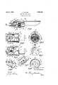
- Fig. ⁇ 1 is a longitudinal section through a lamp-socket embodying the invention.
- Fig. 2y is a longitudinalsection through the socket-shell, showing the socketsvvitch mechanism in elevation.
- Fig. 3 is a vievv similar to Fig. 2 lookingl :from the rethrough the socket on the line 4 4, Fig. l.
- Fig. 5 is an open-end view oi the socket-shell.
- Fig. n is a perspective viewot the socketshell.
- Fig. i( is a perspective view of the support tor the socket-switch mechanism
- Fi 3 is a section on the line 8--8, Fig. 1.
- 'the soclret illustrated comprises a support l molded in one piece trom phenolic condensation material.
- 'Flic support 1 is cylindrical in torno and is provided at one end with a cavity 2 for reception of the lampbase 3.
- 'llhe support 1 is provided with a metallic ring insert 4 and springpin-terminal inserts 5., (i, which engage the filament terminals ci the lampebulb.
- the support 1 is 'termed at the other end, or vend opposite the cavity 2, with a slot a, Fig. 7, dividing it into tvvo spaced projections 7. which have curved sur'liaceportions 8 fitting snugly within the cylindrical shell-member 9.
- the projections 'i' are itorined with recesses 10 which receive the diametrically opposed ribs 11 formed within the shell-member 9. Spaces are pro-y vided 4between the ribs 11 andthe adjacent side-wall portions 12 of the recesses 1() to receive and confine the lead-in wires 13 which are connected to the terminal screws 14, 15.
- Fig. 4 is a transverse section ELECTRIC LAMP SOCKET 1930. Serial No. 463,592.
- the electric switch-mechanism and associated terminal elements 14, 15, are mounted wholly on the support 1 and there are no electrical partsvmounted on the shell 9 which is simply an insulating enclosure for the electrical parts mounted on the support 1.
- the shell-member 9 is molded from plie nolic condensation material and has an endwall 26 inwhich is ametal nipple insert 27 constituting an inlet for the wires 13.
- the skirt of the shell 9 has an opening 28 at the end opposite the end-wall 26.
- the shell-member is tudinal slot 31 for the engages the operating lever 19, as disclosed in my application, Serial No. 285,801, filed June 16, 1928, now Patent 1,805,048 dated May 12 1931.' l
- a one-piece molded shade 33 having at one end an integral ring-portion 34 which externally en,-
- the ring-portion 34 is formed wit the inner lon y'tu nal slots 35 which permit detachment o the shade from the socket when the shade is turned to registerthe slots 35.
- An electric lamp-socket com risin a cylindrical socket-shell formed o material and having internally disposed ribs extending lengthwise of said shell, and 'socket-switch mechanism including a support of insulating material having ortions iitting the inner cylindrical wall oi) said shell and recesses receiving said ribs, there being spaces between said ribs and the adjacent side wall portions of the recesses in said support to receive and confine the lead-in wires.
Landscapes
- Arrangement Of Elements, Cooling, Sealing, Or The Like Of Lighting Devices (AREA)
Description
April 5, 1932. K. PERKINS 1,852,365
ELECTRIC LAMP socxT Filed June 25, 1930 lllnrented wir w32 PATENT OFFICE 'lPEIRlKi'N DF ELItZ,ABETH,-NEW JERSEY, ASSIGNR TO THE SINGER MANU- FatWtWHNG COMPANY, F ELZABETH, NEW JERSEY, A CORPORATION OF NEW .Application tiled June 25,`
This invention relates to electric lamprsoclrets and has for an object to provide a .toeliet oi simplilied and improved construction which is inexpensive to manufacture.
'Flic invention consists in the devices, coinbinations and arrangement of parts hereinuiter described and claimed.
llhe several features of the invention and the advantages attained thereby will be fl readily understood by those skilled in the art itromthe following detailed description oit a preterred embodiment oi the invention, talren in connection with the accompanying drawings in which Fig. `1 is a longitudinal section through a lamp-socket embodying the invention. Fig. 2y is a longitudinalsection through the socket-shell, showing the socketsvvitch mechanism in elevation. Fig. 3 is a vievv similar to Fig. 2 lookingl :from the rethrough the socket on the line 4 4, Fig. l. Fig. 5 is an open-end view oi the socket-shell. Fig. n is a perspective viewot the socketshell. Fig. i( is a perspective view of the support tor the socket-switch mechanism, and Fi 3 is a section on the line 8--8, Fig. 1.
'the soclret illustrated comprises a support l molded in one piece trom phenolic condensation material. 'Flic support 1 is cylindrical in torno and is provided at one end with a cavity 2 for reception of the lampbase 3. 'llhe support 1 is provided with a metallic ring insert 4 and springpin-terminal inserts 5., (i, which engage the filament terminals ci the lampebulb. The support 1 is 'termed at the other end, or vend opposite the cavity 2, with a slot a, Fig. 7, dividing it into tvvo spaced projections 7. which have curved sur'liaceportions 8 fitting snugly within the cylindrical shell-member 9. The projections 'i' are itorined with recesses 10 which receive the diametrically opposed ribs 11 formed within the shell-member 9. Spaces are pro-y vided 4between the ribs 11 andthe adjacent side-wall portions 12 of the recesses 1() to receive and confine the lead-in wires 13 which are connected to the terminal screws 14, 15.
lt/l'ounted in the slot s between the projections T, il, is a toggle-switch mechanism of usual construction and including a stationverse direction. Fig. 4 is a transverse section ELECTRIC LAMP SOCKET 1930. Serial No. 463,592.
ary U-shaped metal supporting frame 16 in which are pivotally supported at 17 and 18 the operating lever 19 and movable .contactmember 20. The usual spring-connection 21 is provided between the lever 19 and movable contact-member 2() to actuate the latter in.
opposite directions with a snap-action. 'The is connected to another spring-leaf-contact 25. The between the leaf-spring-contacts 24 yand 25 and electrically bridges the gap between movable contact-member 20 wipes them. The electric switch-mechanism and associated terminal elements 14, 15, are mounted wholly on the support 1 and there are no electrical partsvmounted on the shell 9 which is simply an insulating enclosure for the electrical parts mounted on the support 1. The shell-member 9 is molded from plie nolic condensation material and has an endwall 26 inwhich is ametal nipple insert 27 constituting an inlet for the wires 13. The skirt of the shell 9 has an opening 28 at the end opposite the end-wall 26. The opening 28 is the full size oi the cylindrical supporting member 1 which latter is inserted through the opening 28 into the shell-member 9. When so inserted, the rim 29 of the shell 9 engages the transverse flange 30 on the support 1, which flange is disposedin a transverse plane between the lamp-base-receiving cavity 2 and the slot s and forms a finished closure for the open end of the shell-member.
The shell-member is tudinal slot 31 for the engages the operating lever 19, as disclosed in my application, Serial No. 285,801, filed June 16, 1928, now Patent 1,805,048 dated May 12 1931.' l
There may also be provided a one-piece molded shade 33 having at one end an integral ring-portion 34 which externally en,-
formed- With a longislide-button 32 which gages thewall of the ylamp-base receivin e cavity 2. The ring-portion 34 is formed wit the inner lon y'tu nal slots 35 which permit detachment o the shade from the socket when the shade is turned to registerthe slots 35.
with the retaining pins 36 on the lamp-basereceiving end of the suport 1.
The socket comprises ut two major pori tions, to wit: the shell 9 and the art 1 which is inserted in the shell 9. The ange on the part'l caps or closes the open end of the shell 9 and renders the use of a separate cap member unnecessarfv.
Having thus set orth the nature of the invention, what I claim herein is:
1. An electric lamp-socket com risin a cylindrical socket-shell formed o material and having internally disposed ribs extending lengthwise of said shell, and 'socket-switch mechanism including a support of insulating material having ortions iitting the inner cylindrical wall oi) said shell and recesses receiving said ribs, there being spaces between said ribs and the adjacent side wall portions of the recesses in said support to receive and confine the lead-in wires.
2. An electric lamp-socket'icomprising a one-piece molded support formed at one end with a lam -base receiving cavity, an electric switch an mounted wholly on the other end of said support, said support having a flange between its ends, and a molded socket-shell having a cylindrical skirt adapted to receive and enclose said other end of the said support together with the switch partsJthereon, said shell having a circuit inlet at one end and' a rim at the other end in engagement with said flange.
3. An electric lamp-socket comprising acylindrical support of molded insulating material formed at one end with a lamp-basereceiving cavity yand at its opposite end with 'a slot dividing it into spaced msulating projections, said rojections having recesses 1n their outer sur ace portions for insulating the lead-in wires, switch-mechanism mounted on said support and including a movable contact element mounted in said slot between said.
projections, and a cylindrical socket-shell of molded material enveloping lSaid insulating projections and Vswitch-mechanism.
In testimony whereof I have signed my name toA this specification.
i UNNETH PERKINS.
insu ating associatedI terminal elements f
Priority Applications (1)
| Application Number | Priority Date | Filing Date | Title |
|---|---|---|---|
| US463592A US1852365A (en) | 1930-06-25 | 1930-06-25 | Electric lamp socket |
Applications Claiming Priority (1)
| Application Number | Priority Date | Filing Date | Title |
|---|---|---|---|
| US463592A US1852365A (en) | 1930-06-25 | 1930-06-25 | Electric lamp socket |
Publications (1)
| Publication Number | Publication Date |
|---|---|
| US1852365A true US1852365A (en) | 1932-04-05 |
Family
ID=23840633
Family Applications (1)
| Application Number | Title | Priority Date | Filing Date |
|---|---|---|---|
| US463592A Expired - Lifetime US1852365A (en) | 1930-06-25 | 1930-06-25 | Electric lamp socket |
Country Status (1)
| Country | Link |
|---|---|
| US (1) | US1852365A (en) |
-
1930
- 1930-06-25 US US463592A patent/US1852365A/en not_active Expired - Lifetime
Similar Documents
| Publication | Publication Date | Title |
|---|---|---|
| US2198504A (en) | Spring lock for electrical contact plugs | |
| US2618676A (en) | Socket structure for double-ended fluorescent lamps | |
| US1820261A (en) | Electric lamp socket | |
| US1852365A (en) | Electric lamp socket | |
| US2292038A (en) | Combined attachment cap and lamp holder | |
| US2119146A (en) | Electric light socket and switch | |
| US1977086A (en) | Combined snap switch for flash lights | |
| US3001165A (en) | Lamp socket and terminal means for printed circuits | |
| US2169868A (en) | Electric socket | |
| US1701476A (en) | Safety socket | |
| US2742620A (en) | Compressible lampholder with torsion spring contacts for double ended discharge lamps | |
| US1321934A (en) | Electric lamp | |
| US1684268A (en) | Incandescent-lamp socket | |
| US1959249A (en) | Electric lamp socket | |
| US1730043A (en) | Electric pull switch and socket | |
| US2561460A (en) | Electric light bulb | |
| US1452321A (en) | Adapter | |
| US1214353A (en) | Conduit-box receptacle. | |
| US1643655A (en) | Electric socket | |
| US1028957A (en) | Plug-socket. | |
| US1575625A (en) | Illuminated gear-shift-lever ball | |
| US2321035A (en) | Shade for fluorescent lamps | |
| US1866985A (en) | Electric connecter | |
| US1714178A (en) | Electrical connecter | |
| US1533771A (en) | Socket plug |