US1852340A - Toy aeroplane - Google Patents
Toy aeroplane Download PDFInfo
- Publication number
- US1852340A US1852340A US119997A US11999726A US1852340A US 1852340 A US1852340 A US 1852340A US 119997 A US119997 A US 119997A US 11999726 A US11999726 A US 11999726A US 1852340 A US1852340 A US 1852340A
- Authority
- US
- United States
- Prior art keywords
- shaft
- plane
- propeller
- aeroplane
- flexible
- Prior art date
- Legal status (The legal status is an assumption and is not a legal conclusion. Google has not performed a legal analysis and makes no representation as to the accuracy of the status listed.)
- Expired - Lifetime
Links
- 230000033001 locomotion Effects 0.000 description 10
- 230000008878 coupling Effects 0.000 description 3
- 238000010168 coupling process Methods 0.000 description 3
- 238000005859 coupling reaction Methods 0.000 description 3
- 238000005452 bending Methods 0.000 description 2
- 238000010276 construction Methods 0.000 description 2
- 238000004088 simulation Methods 0.000 description 2
- 230000009471 action Effects 0.000 description 1
- 229910000086 alane Inorganic materials 0.000 description 1
- AZDRQVAHHNSJOQ-UHFFFAOYSA-N alumane Chemical compound [AlH3] AZDRQVAHHNSJOQ-UHFFFAOYSA-N 0.000 description 1
- 230000008933 bodily movement Effects 0.000 description 1
- 230000008859 change Effects 0.000 description 1
- 230000006872 improvement Effects 0.000 description 1
- 230000007246 mechanism Effects 0.000 description 1
- 239000002184 metal Substances 0.000 description 1
- CMWTZPSULFXXJA-VIFPVBQESA-N naproxen Chemical compound C1=C([C@H](C)C(O)=O)C=CC2=CC(OC)=CC=C21 CMWTZPSULFXXJA-VIFPVBQESA-N 0.000 description 1
- 238000005192 partition Methods 0.000 description 1
- 238000006467 substitution reaction Methods 0.000 description 1
Images
Classifications
-
- A—HUMAN NECESSITIES
- A63—SPORTS; GAMES; AMUSEMENTS
- A63H—TOYS, e.g. TOPS, DOLLS, HOOPS OR BUILDING BLOCKS
- A63H27/00—Toy aircraft; Other flying toys
- A63H27/04—Captive toy aircraft
Definitions
- This invention relates to toy aeroplanes, propeller is mounted on the propeller particularly to the driving mechanism thereshaft 11 in the usual manner.
- the shaft 11 for, and contemplates among other things, is suitably journalled near one end thereof the provision of a source of power entirely in the head 12 of the fuselage 13, and near 5 outside of the plane for rotatingthe propeller the other end thereof in the partition 14.
- shaft. in the propeller shaft 11 is fixed a suitable In toys of the type referred to, the motor gear such as the bevel gear 15, and meshing has heretofore been carried by the plane itwith said gear is the preferably larger bevel self, and has taken the form of springs, rubgear 16.
- My invention includes the provision of a A suitable slot 17 is made in the under 1.3 distant source of power not carried by the side of the fusela e 13 through which the o5 plane, but which is operatively connected to cylindrical bearing member 18 of the frame the propeller, and which is under the control 19 is passed.
- the shaft 20 on which-the of the operator at all times, while the plane bevel gear 16 is mounted, is supported by is allowed to fly freely in all directions and the bearing 18 for rotation therein, the end if) at various controlled speeds Within a definite of said shaft being provided with a suitable range, and for an unlimited period of time. loop as 21, or drilled with a suitable hole,
- the invention contemplates further imthrough which the hook end 22 of the flexible prownients in the art of iiying aeroplanes inshaft 23 is passed in such a manner that roeluding controlling the plane from terra tation of said flexible shaft causes rotation 221 firma and flying the plane continuously for of the bevel gear 16.
- a horizontal bearing mem- A further improvement is the provision of her as 2 1 is made a part of the frame and means on the plane for simulating the sound is loosely mounted on the propeller shaft 11. made by a full sized plane in flight.
- Said bearing 24 is connected to the hearing
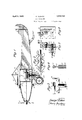
- the various objects of my invention will 18 as by means of the web 25, movement of so be clear from the description which follows the frame or any part thereof longitudinaland from the drawings, in which ly of the shaft 1.1 being prevented by the Fig. 1 is a side elevation and partial vercylinder 26 forming part of said frame and tical section of my improved plane. mounted loosely on.
- the shaft 11 between Fig. 2 is a section of the housing for the the bevel gear 15 and the collar 27 so that as flexible shaft, on a greatly enlarged scale;
- the entire frame 19 and the 16 carried Fig. 3 is a side view and partial section thereby are free to swing. of the frame carrymg the swingable gear of The source of power through which the the plane.
- Fig. 4 is a vertical section of the same taken cated on tcrra firma and is at all times under on the line H of Fig. 3. the control of the operator.
- the range of Fig. 5 is a vertical section of the gear box flight of the plane is of course limited by embodying a proposed form of the source of the length of the flexible shaft.
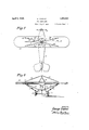
- the flexible '2' is a top plan view of a plane to shaft therefore tends to pull the gear 16 which my invention has been applied, and and the shaft 20 on which it is mounted to- Fig. 8 is a front view of the same. gether with the frame 19 to one side, and
- the supporting frame 19 is swingably mounted on the propeller shaft. It will be seen that the gear 16 is so mounted and supported by the frame 19 that when the flexible shaft 23 is for any reason pulled out of the vertical as when the plane is flown in a circle about the operator, the frame 19 is swung about the shaft 11 carrying with it the gear 16 into a position wherein the least pull is exerted on the plane.
- any suitable means distant from the plane may be provided whereby the plane is not weighted by the motor and the flight may be maintained indefinitely under complete control.
- crank 33 is mounted on the shaft 30 and serves rotate said shaft and the gear 28 thereon at the will of the, operator and at any suitable speed desired.
- the gears 28 and 29 are so proportioned that the shaft 23 is rotated at the proper rate to turn the propeller 10 at the proper speed for propelling the plane. It will be understood that the speed of the plane may be controlled.
- the flexible shaft 23 is suitably connected to the shaft 31 as by means of the hook 34 and the projection 35, similar to the hook and the projection provided at the end of the bevel gear shaft-20, or by means merely ofa suitable hole in the end of theshaft 31 through which the hook 34 is passed.
- a suitable fiexible housing as 36 is provided therefor.
- Said housing consists of a narrow corrugated ribbon preferably of metal and preferably comprising the three loops 37, 38 and 39 made longitudinally throughout the one tire length of the ribbon, said ribbon being wound in a number of turns in overlapping engagement to form a flexible tube.
- the loop 37 at one edge of the ribbon is engaged by and overlaps the loop 39 of the adjacent turn in such a manner that the housing encloses and protects the flexible shaft 23 throughout the length thereof, butv adds little weight thereto.
- wing 40 which is braced by the wires 41, 42, 43 and 44 which are each attached at one of the ends thereof to suitable hooks as 45 on the wing 40 and at the other end en a in the u ier end of the wire supporting post 46.
- Similar wires as 47, 48, 49 and 50 are secured to the underside of the wing at one end, and the other end to a suitable point on the fuselage or onv the wheel frame 51.
- the flexible bands 52 and 53 preferably made of rubber, in such positionthat said bands will be caused to vibrate by thecurrent of air produced durat e l ght of th Pla ea ands ar attached at one end 53 thereof. preferably to. the wing-4O and at the other end thereof to the wheel frame 51 or to any other suitablepointand' are stretched taut ready for vibration.
- the plane is setupon' the groundtorest on. the wheels 54 andon theskid 55. .
- said box may be held in speedihas been imparted to the-propeller the plane will roll along the-ground inth'eusual: manner and then rise, into the air to begin its.
- fiighti As-willbeobvious, the-crank 33- may be replaced by. annutomatic. source of. power, such as a motor provided with suitable controls,*if: desired; It, will be understoodthat the range of-fiight: is limitediby thelengthrof the sha-fti23andthat the plane isunder.
- crank 33 is merely turned'fasterand should it be, desired to-cause the plane to .perform, the usual: acrobatic tricks, rotation of the crank 33 is slowed or stopped thereby lessening or cutting off the power and sending the plane into a nosedive from which the plane may be righted'into itsfnormal flying position by again rotating. the-crank 33 and imparting forward movement to the plane,
- the alane may be brought to the ground gradually and caused to alight in simulation of the action of a full sized plane by gradually reducing the speed of rotation of the propeller.
- the flexible housing 36 prevents kinking or other distortion of the flexible shaft 23 protected thereby other than slight bending, while it is itself sufficiently light and flexible to prevent dragging on the plane.
- the housing is not likely to stretch or to become distorted by reason of the sliding engagement of the adjacent loops 3'? and 39 thereof. If the operators positionis not directly underneath the plane, the pull on the plane due to the weight of the shaft 33 and the housing 36 is minimized by reason of the automatic ad ustment of the frame 24, the bevel gear shaft 20 and the end of the flexible shaft carried thereby, to that angle which exerts the least drag upon the plane, so that the plane is held baclt to a minimum extent.
- the flight of the ilane may be maintained for an unlimited period due to the independent arrangement of the source of power outside of, at a distance from and independently of the plane.
- a revoluble propeller for actuating the plane actuating means for the propeller, including a part movable bodily, indepeiidentl of the movement of the plane, and adapted to have power supplied ereto continuously while the plane is in ii it and a flexible shaft suspended from the plane and operatively connecting the actuating means with the propeller.
- a toy aeroplane capable of flight in all directions within a predetermined range including a revoluble propeller for driving the aeroplane, a flexible rotatable shaft exten ing outside of said aeroplane, allowing substanlly free movement of said aeroplane in all dim-actions Within a distance equal to the length of said shaft, and operatively connected to said propeller, a nd actuating means con nected to the out. do end of said shaft and controllable from the ground for continuously rotating said shaft to fly the aeroplane for as long a time as power continues to be supplied to the actuating means.
- a propeller In a toy aeroplane, a propeller, a shaft, a gear on said shaft, a swingable gear meshing with the first gear, means for supporting the swingable gear and for allowing said swingable gear to adjust itself so that the axis thereof lies in the direction of the pull thereon, a flexible shaft connected to said swingable gear and extending outside of the aeroplane, and means for rotating the flexible shaft.
- a propeller In a toy aeroplane, a propeller, a propeller shaft, pair of intermeshing gears operatively connected to said shaft, means loosely mounted on said shaft fo swiugably supporting one of said gears, a flexible shaft connected at one end thereof to the swingably supported gear, and a source of power controllable from a point in spaced relation to the aeroplane connected to the other'end of said flexible shaft.
- means for causing free flight of the aeroplane including a prosaid second gear for movement about said shaft, and means mechanically connecting said second gear to a distant source of power.
- a revoluble propeller capable of substantially free flight, a revoluble propeller, a propeller shaft, a fear on said shaft, a second revoluble gear meshing with the first gear, means loose on said shaft for supporting said second gear for movement about said shaft, a distant source of power, a flexible shaft connecting said second gear to said source of power, a flexible non-stretchable metallic housing about and preventing distortion of the flexible shaft other than bending, and vibrating means on said aeroplane r producing sound on the light of said aeroplane.
- a hollow substantiah ly closed fuselage, wing and a flexible elastic band secured to said aeroplane near the fuselage and adapted to be vibrated on the flight of the aeroplane for simula a the sound of a full-sized aeroplane in flight, said fuselage acting a sound box.
- a propeller controlling the speed of flight of said aeroplane, a flexible rubber strip stretched taut and arranged to, vibrate by the current of air thrown by the propeller on the propulsion, of the aeroplane by said propeller for producing a sound in simulation of the sound of a fullsized aeroplane in flight.
- a propeller for driving said device means at a distance from the device for operating said propeller, and a stretched rubber strip adapted to vibrate by the air stream from said propeller for simulating the sound of a fullsized aeroplane in flight.
- a toy flying device capable of sub stantially free flight and including a fuselage in the form of a. sound box, means for driving the device, from a distant source mechanically connected to the device, and flexible vibratory sound producing means on said device near said fuselage, said fuselage vibrating on the vibration of said means.
- a propeller In a flying device, a propeller, a propeller shaft, a swingable frame on said shaft, a shaft in said frame arranged angularly to said propeller shaft, a gear on each of said shafts meshing with each other, and means outside of said device for rotating the shaft in said frame.
- a propeller shaft In a flying device, a propeller shaft, a second shaft arranged angularly with respect to said propeller shaft, means hinged on the propeller shaft carrying said second shaft, intermeshing gearing on said shafts, a flexible shaft detachably connected to the second shaft, and non-flying actuating means for rotating the flexible shaft at speeds suflicient to cause the-device to fly.
- a propeller shaft operatively connected to the propeller shaft, and means for swingably supporting the drive shaft, whereby the drive shaft may remain substantially vertical independently of the angular positions assumed by the device.
- a pro peller shaft for imparting motion to said device
- actuating means outside and movable independently of said device for rotating said shaft during the flight of the device
- flexible, rotatable m'eans'for mechanically connecting said actuating means to said shaft said actuating means being operable continuously for an unlimited period and adapted to be fully controlled by an operator while the device is in flight, said connecting means allowing bodily movement of said device relatively to said actuating means in any direction.
- a toy aeroplane unsupported and selfsustaining in flight including a revoluble propeller, a shaft operatively connected to said pr0peller,'said shaft being flexible to allow a change in the distance between the ends thereof and thereby allowing substantially free movement of the aeroplane relatively to the loWer-end-of said shaft during the flight of the aeroplane, said shaft extending below the aeroplane and adding to the gross weight thereof, and means controlled by an operator at said lower end of the shaft for continuously rotating said shaft at speeds sufficient to fly the aeroplane for an unlimited period without stopping.
- means for operating the aeroplane for limited free movement in any direction including gearing mounted in said aeroplane and rotatable means for driving said aeroplane operatively connected to said gearing and depending from the aeroplane, and non-flying actuating means outside of said aeroplane operatively connected to said rotatable means and operating only during the flightv of the aeroplane to maintain the continuous flight of the plane in definitely.
- means for causing substantially free flight of the device including a propeller for the device, a rotatable flexible shaft suspended from the device and operatively connected to said propeller, .and continuously rotatable means at the lower end of said shaft for rotating said shaft, and adapted to be operated while the device is in flight, to cause the deviceto fly continuously during the rotation of said means, and means for preventing undue distortion ofsaid shaft.
- propelling means tierefor, a revoluble flexible shaft suspended from the device for transmitting power to said propelling means while the device is in flight, and a flexible housing for said shaft, and gearing independent of the device for one end of the shaft and continuously rotatable indeflnitely, independently of themovement of the device.
- propelling means for the plane In an aeroplane operated from a distant source of power during the flight thereof, propelling means for the plane, a flexible, rotatable shaft operatively connecting the propelling means to the source of power, a flexible housing for the shaft, and continuously rotatable means including the distant source of powerand operated from the ground for rotating said shaft while the plane is in flight.
- a toy aeroplane including a revoluble propeller, revoluble actuating .means arranged in variable spaced relation to the aeroplane and adaptedto be controlled at will by an operator outside oftheaeroplane, rev- 7 oluble means suspended from the aeroplane and operatively connected to said propeller and to said actuating means for rotating the propeller continuously and for an indefinitely long period at varying desired speeds whereby said aeroplane may be givenl'imited movement in anydirection relatively to said actuating means.
Landscapes
- Toys (AREA)
Description
G VLAHOV TOY AEROPLANE April 5, 1932;
Filed July 2. 1926 2 Sheets-5heet 555% W m m wm 5:55. QM
m V W m m m V a. M
April 5, 1932. G. VLAHOV 1,852,340
TOY AEROPLANE Filed July 2, 1926 2 Sheets-Sheet 2 1N VEN TOR.
George Via/70v M A TTORNEYS.
Patented Apr. 5, 1932 burrs!) STATES PATENT OFFICE GEORGE VLAHOV, OF NEW YORK, N. Y., ASSIGNOR 'I'O JOHN HOLTZMAN, OF NEW YORK, N. Y.
TOY AEROILANE Application filed July 2, 1926. Serial No. 119,997.
This invention relates to toy aeroplanes, propeller is mounted on the propeller particularly to the driving mechanism thereshaft 11 in the usual manner. The shaft 11 for, and contemplates among other things, is suitably journalled near one end thereof the provision of a source of power entirely in the head 12 of the fuselage 13, and near 5 outside of the plane for rotatingthe propeller the other end thereof in the partition 14. shaft. (in the propeller shaft 11 is fixed a suitable In toys of the type referred to, the motor gear such as the bevel gear 15, and meshing has heretofore been carried by the plane itwith said gear is the preferably larger bevel self, and has taken the form of springs, rubgear 16. It will be seen that rotation of the in her hands or the like adapted to be wound gear 16 will cause rotation of the propeller, so up and during the unwinding thereof to roand that when a suflicient speed of rotation is tate the propeller and thereby to force the attained, the plane is caused to fly through the plane uncontrolledly through the air. air.
My invention includes the provision of a A suitable slot 17 is made in the under 1.3 distant source of power not carried by the side of the fusela e 13 through which the o5 plane, but which is operatively connected to cylindrical bearing member 18 of the frame the propeller, and which is under the control 19 is passed. The shaft 20 on which-the of the operator at all times, while the plane bevel gear 16 is mounted, is supported by is allowed to fly freely in all directions and the bearing 18 for rotation therein, the end if) at various controlled speeds Within a definite of said shaft being provided with a suitable range, and for an unlimited period of time. loop as 21, or drilled with a suitable hole,
The invention contemplates further imthrough which the hook end 22 of the flexible prownients in the art of iiying aeroplanes inshaft 23 is passed in such a manner that roeluding controlling the plane from terra tation of said flexible shaft causes rotation 221 firma and flying the plane continuously for of the bevel gear 16. For suitably supportan unlimited period and at any desired speed. ing the frame 19 a horizontal bearing mem- A further improvement is the provision of her as 2 1 is made a part of the frame and means on the plane for simulating the sound is loosely mounted on the propeller shaft 11. made by a full sized plane in flight. Said bearing 24: is connected to the hearing The various objects of my invention will 18 as by means of the web 25, movement of so be clear from the description which follows the frame or any part thereof longitudinaland from the drawings, in which ly of the shaft 1.1 being prevented by the Fig. 1 is a side elevation and partial vercylinder 26 forming part of said frame and tical section of my improved plane. mounted loosely on. the shaft 11 between Fig. 2 is a section of the housing for the the bevel gear 15 and the collar 27 so that as flexible shaft, on a greatly enlarged scale; the entire frame 19 and the 16 carried Fig. 3 is a side view and partial section thereby are free to swing. of the frame carrymg the swingable gear of The source of power through which the the plane. flexible shaft 23 is driven is preferably lo- Fig. 4 is a vertical section of the same taken cated on tcrra firma and is at all times under on the line H of Fig. 3. the control of the operator. The range of Fig. 5 is a vertical section of the gear box flight of the plane is of course limited by embodying a proposed form of the source of the length of the flexible shaft. When the the power. plane is in full flight, it is pulled by the flexi U Il ig. G is a front View of the same. ble shaft toward the operator. The flexible '2' is a top plan view of a plane to shaft therefore tends to pull the gear 16 which my invention has been applied, and and the shaft 20 on which it is mounted to- Fig. 8 is a front view of the same. gether with the frame 19 to one side, and
in one of the practical applications of my might exert an undesirable drag on the plane invention which will now be described, the tending to reduce the speed or stop the flight.
It is for the purpose of minimizing the pull or drag of the flexible shaft on the gear 16 that the supporting frame 19 is swingably mounted on the propeller shaft. It will be seen that the gear 16 is so mounted and supported by the frame 19 that when the flexible shaft 23 is for any reason pulled out of the vertical as when the plane is flown in a circle about the operator, the frame 19 is swung about the shaft 11 carrying with it the gear 16 into a position wherein the least pull is exerted on the plane.
For rotating the flexible shaft 23 any suitable means distant from the plane may be provided whereby the plane is not weighted by the motor and the flight may be maintained indefinitely under complete control. For economy, simplicity and ease of construction however, I prefer to provide the 28 and 29 supported on the shafts 30 and 31 respectively in the gear 130x32. ii crank 33 is mounted on the shaft 30 and serves rotate said shaft and the gear 28 thereon at the will of the, operator and at any suitable speed desired. The gears 28 and 29 are so proportioned that the shaft 23 is rotated at the proper rate to turn the propeller 10 at the proper speed for propelling the plane. It will be understood that the speed of the plane may be controlled. by the o1 erator by rotating the crank 33 at a greater or at a lesser speed as desired and that the plane may be caused to take off, to alight, to dive, and to perform tricks by starting, stopping and varying the speed of rotation of the crank. The flexible shaft 23 is suitably connected to the shaft 31 as by means of the hook 34 and the projection 35, similar to the hook and the projection provided at the end of the bevel gear shaft-20, or by means merely ofa suitable hole in the end of theshaft 31 through which the hook 34 is passed.
Forv preventing the kinking, knotting, or looping of the flexible shaft 23, and for keeping said shaft asstraight as possible, a suitable fiexible housing as 36 is provided therefor. Said housing consists of a narrow corrugated ribbon preferably of metal and preferably comprising the three loops 37, 38 and 39 made longitudinally throughout the one tire length of the ribbon, said ribbon being wound in a number of turns in overlapping engagement to form a flexible tube. The loop 37 at one edge of the ribbon is engaged by and overlaps the loop 39 of the adjacent turn in such a manner that the housing encloses and protects the flexible shaft 23 throughout the length thereof, butv adds little weight thereto. By reason of the overlapping of 1 the ad'acent loo s 37 and 39 the various inunder considerable tension, While. the, fleXi-Z :bility' of-the hous ng is unimpaired. The;
plane is provided with the usual wing 40 which is braced by the wires 41, 42, 43 and 44 which are each attached at one of the ends thereof to suitable hooks as 45 on the wing 40 and at the other end en a in the u ier end of the wire supporting post 46. Similar wires as 47, 48, 49 and 50 are secured to the underside of the wing at one end, and the other end to a suitable point on the fuselage or onv the wheel frame 51. I
To accentuate the sound produced by the propeller 10 as the plane travels through the air and to imitate the sound produced by a full-sized plane in flight, I arrange the flexible bands 52 and 53 preferably made of rubber, in such positionthat said bands will be caused to vibrate by thecurrent of air produced durat e l ght of th Pla ea ands ar attached at one end 53 thereof. preferably to. the wing-4O and at the other end thereof to the wheel frame 51 or to any other suitablepointand' are stretched taut ready for vibration.
F or suit-ably supporting the housing 3.6 in. position the endsthereof are flanged asat56 to engage the inner-surfaceof the bottom 57 of a suitable coupling 58. One of said. couplings is. threadedainter nally atthe upper, end 59 thereof to engage the threads 60-01"? the. bearing 18. while the other of; said couplings; is. threaded; similarly to engage the threads 61 of-the bushing 62-surrounding-. the shaft 31 and securechto the gear box 32.
The. operation of my in'iproved deviceisas. follows; 7
The plane is setupon' the groundtorest on. the wheels 54 andon theskid 55. .Wherethe gear box 32 is used, said box may be held in speedihas been imparted to the-propeller the plane will roll along the-ground inth'eusual: manner and then rise, into the air to begin its. fiighti As-willbeobvious, the-crank 33- may be replaced by. annutomatic. source of. power, such as a motor provided with suitable controls,*if: desired; It, will be understoodthat the range of-fiight: is limitediby thelengthrof the sha-fti23andthat the plane isunder. the
control of the operator at all times. Should.
itbe desired, togmake the plane fly higher,
then the crank 33 is merely turned'fasterand should it be, desired to-cause the plane to .perform, the usual: acrobatic tricks, rotation of the crank 33 is slowed or stopped thereby lessening or cutting off the power and sending the plane into a nosedive from which the plane may be righted'into itsfnormal flying position by again rotating. the-crank 33 and imparting forward movement to the plane,
by the'properadjustment of the wings as will 7 1' be readily understood, the plane may be reused to perform other tricks not necessary to be explained herein in detail. The alane may be brought to the ground gradually and caused to alight in simulation of the action of a full sized plane by gradually reducing the speed of rotation of the propeller.
The flexible housing 36 prevents kinking or other distortion of the flexible shaft 23 protected thereby other than slight bending, while it is itself sufficiently light and flexible to prevent dragging on the plane. The housing is not likely to stretch or to become distorted by reason of the sliding engagement of the adjacent loops 3'? and 39 thereof. If the operators positionis not directly underneath the plane, the pull on the plane due to the weight of the shaft 33 and the housing 36 is minimized by reason of the automatic ad ustment of the frame 24, the bevel gear shaft 20 and the end of the flexible shaft carried thereby, to that angle which exerts the least drag upon the plane, so that the plane is held baclt to a minimum extent. The flight of the ilane may be maintained for an unlimited period due to the independent arrangement of the source of power outside of, at a distance from and independently of the plane.
It will be understood that various changes may be made from the preferred structure shown and described such as the substitution of an .ctric motor or other source of power for the gear box and hand operated gears, changes in the construction and arrangement of the gears mounted in the plane for rotating the propeller shaft, changes in the form of the housing and other changes which are contemplated but which need not be here set forth in detail all of which changes, fall within the spirit of this invention and the scope of the appended claims.
it claim:
i. In a toy aeroplane, a revoluble propeller for actuating the plane, actuating means for the propeller, including a part movable bodily, indepeiidentl of the movement of the plane, and adapted to have power supplied ereto continuously while the plane is in ii it and a flexible shaft suspended from the plane and operatively connecting the actuating means with the propeller.
A toy aeroplane capable of flight in all directions within a predetermined range including a revoluble propeller for driving the aeroplane, a flexible rotatable shaft exten ing outside of said aeroplane, allowing substanlly free movement of said aeroplane in all dim-actions Within a distance equal to the length of said shaft, and operatively connected to said propeller, a nd actuating means con nected to the out. do end of said shaft and controllable from the ground for continuously rotating said shaft to fly the aeroplane for as long a time as power continues to be supplied to the actuating means.
3. In a toy aeroplane, a propeller, a shaft, a gear on said shaft, a swingable gear meshing with the first gear, means for supporting the swingable gear and for allowing said swingable gear to adjust itself so that the axis thereof lies in the direction of the pull thereon, a flexible shaft connected to said swingable gear and extending outside of the aeroplane, and means for rotating the flexible shaft.
l. In a toy aeroplane, a propeller, a propeller shaft, pair of intermeshing gears operatively connected to said shaft, means loosely mounted on said shaft fo swiugably supporting one of said gears, a flexible shaft connected at one end thereof to the swingably supported gear, and a source of power controllable from a point in spaced relation to the aeroplane connected to the other'end of said flexible shaft.
5. In a toy aeroplane, means for causing free flight of the aeroplane including a prosaid second gear for movement about said shaft, and means mechanically connecting said second gear to a distant source of power.
7. In a toy aeroplane capable of substantially free flight, a revoluble propeller, a propeller shaft, a fear on said shaft, a second revoluble gear meshing with the first gear, means loose on said shaft for supporting said second gear for movement about said shaft, a distant source of power, a flexible shaft connecting said second gear to said source of power, a flexible non-stretchable metallic housing about and preventing distortion of the flexible shaft other than bending, and vibrating means on said aeroplane r producing sound on the light of said aeroplane.
8. In a toy aeroplane, a hollow substantiah ly closed fuselage, wing: and a flexible elastic band secured to said aeroplane near the fuselage and adapted to be vibrated on the flight of the aeroplane for simula a the sound of a full-sized aeroplane in flight, said fuselage acting a sound box. 7
9. In a toy aeroplane, a propeller controlling the speed of flight of said aeroplane, a flexible rubber strip stretched taut and arranged to, vibrate by the current of air thrown by the propeller on the propulsion, of the aeroplane by said propeller for producing a sound in simulation of the sound of a fullsized aeroplane in flight.
10. In a toy flying device, capable of selfsustaining flight within a given range, a propeller for driving said device, means at a distance from the device for operating said propeller, and a stretched rubber strip adapted to vibrate by the air stream from said propeller for simulating the sound of a fullsized aeroplane in flight.
11. In a toy flying device capable of sub stantially free flight and including a fuselage in the form of a. sound box, means for driving the device, from a distant source mechanically connected to the device, and flexible vibratory sound producing means on said device near said fuselage, said fuselage vibrating on the vibration of said means.
12. In a flying device, a propeller, a propeller shaft, a swingable frame on said shaft, a shaft in said frame arranged angularly to said propeller shaft, a gear on each of said shafts meshing with each other, and means outside of said device for rotating the shaft in said frame.
13. In a flying device, a propeller shaft, a second shaft arranged angularly with respect to said propeller shaft, means hinged on the propeller shaft carrying said second shaft, intermeshing gearing on said shafts, a flexible shaft detachably connected to the second shaft, and non-flying actuating means for rotating the flexible shaft at speeds suflicient to cause the-device to fly.
14. In a flying device, a propeller shaft, a drive shaft operatively connected to the propeller shaft, and means for swingably supporting the drive shaft, whereby the drive shaft may remain substantially vertical independently of the angular positions assumed by the device.
15. In an unsupported flying device, a pro peller shaft, a propeller on said shaft for imparting motion to said device, actuating means outside and movable independently of said device for rotating said shaft during the flight of the device, and flexible, rotatable m'eans'for mechanically connecting said actuating means to said shaft, said actuating means being operable continuously for an unlimited period and adapted to be fully controlled by an operator while the device is in flight, said connecting means allowing bodily movement of said device relatively to said actuating means in any direction.
16. A toy aeroplane unsupported and selfsustaining in flight, including a revoluble propeller, a shaft operatively connected to said pr0peller,'said shaft being flexible to allow a change in the distance between the ends thereof and thereby allowing substantially free movement of the aeroplane relatively to the loWer-end-of said shaft during the flight of the aeroplane, said shaft extending below the aeroplane and adding to the gross weight thereof, and means controlled by an operator at said lower end of the shaft for continuously rotating said shaft at speeds sufficient to fly the aeroplane for an unlimited period without stopping.
17. In a toy aeroplane, means for operating the aeroplane for limited free movement in any direction, including gearing mounted in said aeroplane and rotatable means for driving said aeroplane operatively connected to said gearing and depending from the aeroplane, and non-flying actuating means outside of said aeroplane operatively connected to said rotatable means and operating only during the flightv of the aeroplane to maintain the continuous flight of the plane in definitely.
18. In a flying device, means for causing substantially free flight of the device including a propeller for the device, a rotatable flexible shaft suspended from the device and operatively connected to said propeller, .and continuously rotatable means at the lower end of said shaft for rotating said shaft, and adapted to be operated while the device is in flight, to cause the deviceto fly continuously during the rotation of said means, and means for preventing undue distortion ofsaid shaft.
'19. In a flying device, propelling means tierefor, a revoluble flexible shaft suspended from the device for transmitting power to said propelling means while the device is in flight, and a flexible housing for said shaft, and gearing independent of the device for one end of the shaft and continuously rotatable indeflnitely, independently of themovement of the device.
20. In an aeroplane operated from a distant source of power during the flight thereof, propelling means for the plane, a flexible, rotatable shaft operatively connecting the propelling means to the source of power, a flexible housing for the shaft, and continuously rotatable means including the distant source of powerand operated from the ground for rotating said shaft while the plane is in flight.
21. A toy aeroplane including a revoluble propeller, revoluble actuating .means arranged in variable spaced relation to the aeroplane and adaptedto be controlled at will by an operator outside oftheaeroplane, rev- 7 oluble means suspended from the aeroplane and operatively connected to said propeller and to said actuating means for rotating the propeller continuously and for an indefinitely long period at varying desired speeds whereby said aeroplane may be givenl'imited movement in anydirection relatively to said actuating means.
" GEORGE VLAHOV.
Priority Applications (1)
| Application Number | Priority Date | Filing Date | Title |
|---|---|---|---|
| US119997A US1852340A (en) | 1926-07-02 | 1926-07-02 | Toy aeroplane |
Applications Claiming Priority (1)
| Application Number | Priority Date | Filing Date | Title |
|---|---|---|---|
| US119997A US1852340A (en) | 1926-07-02 | 1926-07-02 | Toy aeroplane |
Publications (1)
| Publication Number | Publication Date |
|---|---|
| US1852340A true US1852340A (en) | 1932-04-05 |
Family
ID=22387645
Family Applications (1)
| Application Number | Title | Priority Date | Filing Date |
|---|---|---|---|
| US119997A Expired - Lifetime US1852340A (en) | 1926-07-02 | 1926-07-02 | Toy aeroplane |
Country Status (1)
| Country | Link |
|---|---|
| US (1) | US1852340A (en) |
Cited By (4)
| Publication number | Priority date | Publication date | Assignee | Title |
|---|---|---|---|---|
| US2595650A (en) * | 1950-03-10 | 1952-05-06 | Warren G Eppler | Model airplane flight control |
| US2756537A (en) * | 1952-12-23 | 1956-07-31 | Ernst Max | Drive-equipped toy aeroplane |
| US2801494A (en) * | 1954-12-31 | 1957-08-06 | Ernst Max | Remotely controlled toy aircraft |
| US3018585A (en) * | 1958-02-28 | 1962-01-30 | Stanzel Victor | Remotely powered propulsion and control mechanism for model aircraft |
-
1926
- 1926-07-02 US US119997A patent/US1852340A/en not_active Expired - Lifetime
Cited By (5)
| Publication number | Priority date | Publication date | Assignee | Title |
|---|---|---|---|---|
| US2595650A (en) * | 1950-03-10 | 1952-05-06 | Warren G Eppler | Model airplane flight control |
| US2756537A (en) * | 1952-12-23 | 1956-07-31 | Ernst Max | Drive-equipped toy aeroplane |
| US2795895A (en) * | 1952-12-23 | 1957-06-18 | Arnold & Co K | Captive toy airplane |
| US2801494A (en) * | 1954-12-31 | 1957-08-06 | Ernst Max | Remotely controlled toy aircraft |
| US3018585A (en) * | 1958-02-28 | 1962-01-30 | Stanzel Victor | Remotely powered propulsion and control mechanism for model aircraft |
Similar Documents
| Publication | Publication Date | Title |
|---|---|---|
| US2039676A (en) | Aircraft | |
| US3903639A (en) | Annular winged model airplane | |
| US1852340A (en) | Toy aeroplane | |
| US2801494A (en) | Remotely controlled toy aircraft | |
| US2837864A (en) | Toy aeroplane | |
| US1574567A (en) | Device for steering aircraft | |
| US2390307A (en) | Gas powered model airplane control line apparatus | |
| CN106828922A (en) | The position control mechanism that a kind of imitative insect wing is flapped | |
| US4752271A (en) | Rubber band powered toy balloon | |
| US2382347A (en) | Toy helicopter | |
| US2826860A (en) | Flying saucer toy | |
| US1775861A (en) | Flying machine | |
| US2688206A (en) | Toy helicopter | |
| US1802139A (en) | Airplane toy | |
| US2219658A (en) | Airplane toy | |
| US1385634A (en) | Mechanical toy | |
| US2642698A (en) | Tethered helicopter top | |
| US1895871A (en) | Aeroplane | |
| US2114212A (en) | Motorless toy airplane | |
| US1947982A (en) | Amusement apparatus | |
| US1031623A (en) | Propelling mechanism for aerocraft. | |
| US1867759A (en) | Aircraft | |
| US2527274A (en) | Ratio control for captive airplanes | |
| US3705720A (en) | Toy aircraft roundabout with flexible control tether | |
| US1761690A (en) | Variable pitch and reversible propeller |