US1852337A - Truss - Google Patents
Truss Download PDFInfo
- Publication number
- US1852337A US1852337A US214609A US21460927A US1852337A US 1852337 A US1852337 A US 1852337A US 214609 A US214609 A US 214609A US 21460927 A US21460927 A US 21460927A US 1852337 A US1852337 A US 1852337A
- Authority
- US
- United States
- Prior art keywords
- pad
- members
- pads
- truss
- heads
- Prior art date
- Legal status (The legal status is an assumption and is not a legal conclusion. Google has not performed a legal analysis and makes no representation as to the accuracy of the status listed.)
- Expired - Lifetime
Links
- 230000033001 locomotion Effects 0.000 description 10
- 238000010276 construction Methods 0.000 description 7
- 210000005069 ears Anatomy 0.000 description 6
- 206010019909 Hernia Diseases 0.000 description 4
- 210000003205 muscle Anatomy 0.000 description 3
- 230000010355 oscillation Effects 0.000 description 3
- 230000003292 diminished effect Effects 0.000 description 1
- 230000000694 effects Effects 0.000 description 1
- 230000002452 interceptive effect Effects 0.000 description 1
- 239000010985 leather Substances 0.000 description 1
- 239000000463 material Substances 0.000 description 1
- 239000002184 metal Substances 0.000 description 1
- 230000004048 modification Effects 0.000 description 1
- 238000012986 modification Methods 0.000 description 1
- 230000003387 muscular Effects 0.000 description 1
- 230000003534 oscillatory effect Effects 0.000 description 1
- 238000003825 pressing Methods 0.000 description 1
- 238000000926 separation method Methods 0.000 description 1
Images
Classifications
-
- A—HUMAN NECESSITIES
- A61—MEDICAL OR VETERINARY SCIENCE; HYGIENE
- A61F—FILTERS IMPLANTABLE INTO BLOOD VESSELS; PROSTHESES; DEVICES PROVIDING PATENCY TO, OR PREVENTING COLLAPSING OF, TUBULAR STRUCTURES OF THE BODY, e.g. STENTS; ORTHOPAEDIC, NURSING OR CONTRACEPTIVE DEVICES; FOMENTATION; TREATMENT OR PROTECTION OF EYES OR EARS; BANDAGES, DRESSINGS OR ABSORBENT PADS; FIRST-AID KITS
- A61F5/00—Orthopaedic methods or devices for non-surgical treatment of bones or joints; Nursing devices ; Anti-rape devices
- A61F5/01—Orthopaedic devices, e.g. long-term immobilising or pressure directing devices for treating broken or deformed bones such as splints, casts or braces
- A61F5/30—Pressure pads
Definitions
- This invention relates to trusses and has for its object to provide a device of this character which is adjustable to accommodate persons of different sizes, and in which the pads are adjustable to apply pressure at different angles and locations and are self adjustable to accommodate movements of the body with the least possible discomfort to the wearer. More especially the object is to provide for a simplification of trusses possessing the properties above outlined, and which are adapted for use in cases where the hernia or rupture is of either mild or severe character.
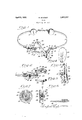
- Figure 1 is a perspective view of a truss embodying the invention, the customary coverings for the pads and holder being omitted.
- Figure 2 is an enlarged horizontal section taken through one of the front pads and the supporting elements therefor.
- Figure 3 is an end or edge view of the construction shown in Figure 2.
- Figure 4 is an inner face View of the pad shown by Figure 3.
- Figure 5 is an inverted end view of the same pad.
- Figure 6 is a cross section taken through the other front pad of the truss.
- Figure 7 is a section taken on the line VII- VH of Figure 6.
- 1 indicates two oppositely bowed resilient members adjustably connected together by an intermediate back section 2, and cooperating with the latter in constituting the holder of the appliance, the holder thus constituting in effect a split ring which extends across the back and around the sides of the wearer, and mounted adjustably upon the members of and within the holder is a pair of back pads 23 which are mounted for oscillation in any direction so as to accommodate themselves to the wearers back and to the movements of the muscles thereof with the least possible inconvenience.
- the special construction and mounting of the pads 3 may vary but preferably correspond to the construction of the pad illustrated by Figures 6 and 7 and herein- 5:; after described in detail.
- Short arms 9 are provided at their outer ends with heads 10 having their rear faces flattened for fitting flatly against the flattened front faces of heads 6, and heads 10 are provided with toothed sockets 11 to receive and interlock with the threaded bosses 7, and thus hold said members rigidly together as regards relative rotative movement.
- the heads 10 are also provided with axial passages 12 registering with the threaded passages 8, and clamping screws 13 extend through heads 10 and engage the threaded passages 8.
- the screws 13 have heads 14 whereby they may be turned readily by hand, and said heads bear against the heads 10 to prevent arms 9 having outward slidable movement and hence disengagement from the toothed bosses of the bolts 5.
- arms 9 are provided with longitudinally threaded passages 15 for engagement by screws 16 extending through lugs 17 at the adjacent ends of the arms, it being noted that said lugs are pivoted on said screws so as to be capable of oscillation thereon. It will also be noted that arms 9 have inwardly-projecting perforated lugs 18, for a purpose hereinafter explained.
- I preferably provide one or both ends of the holder with a pad or pads of elongated and substantially elliptic form.
- a pad or pads of elongated and substantially elliptic form consists of a front member 19 and a back member 20, the latter being provided along the line of the maj or axis of the pad and near each end thereof with over- 100 lapping lugs 21 and 22, pivoted together as at 23, the back member for applying pressure more efi ectively having an elongated rib portion 24.
- the front member is fastened to an arm 25 of lug 17, and above and below the same is provided with buttons or projections 26.
- the back member is capable of rocking'around an upright axis so as to accommodate the contour of the body and the play of the muscles thereof without materially affecting the application of pressure by the rib portion 24 at the point where continual support is necessary.
- a spring 27 is fastened to lug 18, and extends between the mmebers 19 and 20 and is fastened as at 28 to the member 19, it being noted that the spring thus acts to maintain the pad as a whole against unrestricted pivotal movement around screw 16, and yet permits sufficient movement to accommodate the contour of the body and the play of the muscles thereof without imposing undue pressure thereon.
- the pad or pads described may be dispensed with and a circular pad or pair of pads substituted therefor.
- Such pad corresponds preferably in construction and function to the circular pad shown in Figure 1 adjacent the elongated pad described.
- the lug 17 is preferably cast on or secured to the front or outer member 29, and a screw fixed to a lug corresponding to lug 16, extends through said lag and into the corresponding arm 9.
- the member 29 is provided with a central boss 30 having a concave rear face 31, and, with a threaded passage 32 extending axially through the boss.
- the inner member 33 which is: also circular in form, is equipped with a hollow boss 3d engaging the concave face 31, and said boss contains a large semi-circular nut 35 engaged by a clamp screw 36 which is screwed through the boss 30 and extends through an opening 37 in the hollow boss and engages the nut 35, the opening 3'1, being of such size that the member 33 can oscillate against the concave face 31 of boss 30 without detachment therefrom, but to hold the members normally insubstantially parallel relation and yieldingly spaced; apart, a helical spring 38 surrounds the boss and bears against the adj acent faces of the members 29 and 33.
- FIG. 6 shows the device with the members in the closest relationit is possible to dispose the members; when in parallel relation, although it is, obvious that To prevent undue freedom of move-' member 33, which applies pressure on the body of the wearer, is capable of oscillation in any direction so as to accommodate the contour or angle of the body and yet maintain a firm pressure thereon for the full area of said member 33.
- the members 20 and 33 will be provided with a covering of leather or any other suitable padding material, to not only protect the body from direct contact with the metal but also to guard against corrosive action of the latter, and this same statement applies to the back pads 3; and to the members 1 and 20011- stituting the holder, as the parts just enumerated all come into contact either continuously or at times with the body of the wearer or with wearing apparel between the body and the truss.
- the pressure applying pads not only accommodate body contour and muscular movements, but through adjustment of the arms on the threaded shanks, the pads may be brought to hear at many different points on the body, as they can be swungaround the axes of their respective clamping bolts 13, and they may also be disposed at different angles by rotary adjustment of the bolts 5 in the sockets 4.
- the screw 36 serves as a mount or support for a button 39 for engagement by the corresponding ends of a pair of flexible straps 40 adapted to be respectively engaged with the buttons 3.6 of the elongated pad.
- the straps thus serve to complete the encirclement of the body of the wearer and to assist in holding the pads in position without interfering with their independence as. regards oscillating movement, itbeing noted that the straps have a plurality of button holes 41, so as to accommodate any relative adjustment .Which it maybe desired to make between the pads.
- a pad comprising a verticallyelongated. outer plate member having a pair III of inwardly-projecting spaced ears in the plane of its major axis and respectively 1ocated near the upper and lower ends of the member, a second or inner vertically-elongat- 5 ed plate member spaced from the outer plate and provided with a pair of ears respectively engaging flatwise with the ears of the firstnamed plate member, alined pivots respectively connecting engaged ears of the two members, an arm forming a swivel support for the outer plate member, and a substantially circular spring extending through said arm and occupying a plane between said members and the sets of ears thereof and attached at its ends to the outer plate member at a point equally distant from said sets of engaging ears and at the opposite side thereof from its point of engagement with the said arm and in the horizontal plane of the latter.
Landscapes
- Health & Medical Sciences (AREA)
- Nursing (AREA)
- Orthopedic Medicine & Surgery (AREA)
- Engineering & Computer Science (AREA)
- Biomedical Technology (AREA)
- Heart & Thoracic Surgery (AREA)
- Vascular Medicine (AREA)
- Life Sciences & Earth Sciences (AREA)
- Animal Behavior & Ethology (AREA)
- General Health & Medical Sciences (AREA)
- Public Health (AREA)
- Veterinary Medicine (AREA)
- Orthopedics, Nursing, And Contraception (AREA)
Description
R. SCHMEDT April 5, 1932.
TRUSS Filed Aug. 22. 1927 I N V EN TOR.
daZp/zHc/z WATTORNEYS.
Patented Apr. 5, 1932 PATENT OFFICE RUDOLPH SCHMIDT, OF KANSAS CITY, KANSAS TRUSS Application filed August 22, 1927. Serial No. 214,609.
This invention relates to trusses and has for its object to provide a device of this character which is adjustable to accommodate persons of different sizes, and in which the pads are adjustable to apply pressure at different angles and locations and are self adjustable to accommodate movements of the body with the least possible discomfort to the wearer. More especially the object is to provide for a simplification of trusses possessing the properties above outlined, and which are adapted for use in cases where the hernia or rupture is of either mild or severe character.
lVit-h these general objects in view, the invention consists in certain novel and useful features of construction and combinations of parts as hereinafter described and claimed; and in order that it may be fully understood, reference is to be had to the accompanying drawings, in which:
Figure 1 is a perspective view of a truss embodying the invention, the customary coverings for the pads and holder being omitted.
Figure 2 is an enlarged horizontal section taken through one of the front pads and the supporting elements therefor.
Figure 3 is an end or edge view of the construction shown in Figure 2.
Figure 4 is an inner face View of the pad shown by Figure 3.
Figure 5 is an inverted end view of the same pad.
Figure 6 is a cross section taken through the other front pad of the truss.
Figure 7 is a section taken on the line VII- VH of Figure 6.
Referring to the drawings in detail, 1 indicates two oppositely bowed resilient members adjustably connected together by an intermediate back section 2, and cooperating with the latter in constituting the holder of the appliance, the holder thus constituting in effect a split ring which extends across the back and around the sides of the wearer, and mounted adjustably upon the members of and within the holder is a pair of back pads 23 which are mounted for oscillation in any direction so as to accommodate themselves to the wearers back and to the movements of the muscles thereof with the least possible inconvenience. The special construction and mounting of the pads 3 may vary but preferably correspond to the construction of the pad illustrated by Figures 6 and 7 and herein- 5:; after described in detail.
Secured by rivets or otherwise to the front ends of members 1, are internally threaded sockets 4 engaged by bolts 5 provided with rounded heads 6 having flat or smooth outer faces and formed with forwardly-projecting cylindrical bosses 7 peripherally toothed as shown in Figure 2, and said heads 6 are provided with threaded passages 8 which extend axially through the toothed bosses 7.
Short arms 9 are provided at their outer ends with heads 10 having their rear faces flattened for fitting flatly against the flattened front faces of heads 6, and heads 10 are provided with toothed sockets 11 to receive and interlock with the threaded bosses 7, and thus hold said members rigidly together as regards relative rotative movement. The heads 10 are also provided with axial passages 12 registering with the threaded passages 8, and clamping screws 13 extend through heads 10 and engage the threaded passages 8. The screws 13 have heads 14 whereby they may be turned readily by hand, and said heads bear against the heads 10 to prevent arms 9 having outward slidable movement and hence disengagement from the toothed bosses of the bolts 5. At their opposite ends the arms 9 are provided with longitudinally threaded passages 15 for engagement by screws 16 extending through lugs 17 at the adjacent ends of the arms, it being noted that said lugs are pivoted on said screws so as to be capable of oscillation thereon. It will also be noted that arms 9 have inwardly-projecting perforated lugs 18, for a purpose hereinafter explained.
For severe cases of hernia or the like, where it is desired to apply pressure over a considerable area, I preferably provide one or both ends of the holder with a pad or pads of elongated and substantially elliptic form. Such pad consists of a front member 19 and a back member 20, the latter being provided along the line of the maj or axis of the pad and near each end thereof with over- 100 lapping lugs 21 and 22, pivoted together as at 23, the back member for applying pressure more efi ectively having an elongated rib portion 24. The front member is fastened to an arm 25 of lug 17, and above and below the same is provided with buttons or projections 26. It will be noted that by pivoting the two mmebers of the pad together as explained, the back member is capable of rocking'around an upright axis so as to accommodate the contour of the body and the play of the muscles thereof without materially affecting the application of pressure by the rib portion 24 at the point where continual support is necessary. ment around the screw 16 in a direction at right angles to, the movement of member 20 or member 19, as above explained, a spring 27 is fastened to lug 18, and extends between the mmebers 19 and 20 and is fastened as at 28 to the member 19, it being noted that the spring thus acts to maintain the pad as a whole against unrestricted pivotal movement around screw 16, and yet permits sufficient movement to accommodate the contour of the body and the play of the muscles thereof without imposing undue pressure thereon.
For mild cases of hernia or rupture, the pad or pads described may be dispensed with and a circular pad or pair of pads substituted therefor. Such pad corresponds preferably in construction and function to the circular pad shown in Figure 1 adjacent the elongated pad described. In this case the lug 17 is preferably cast on or secured to the front or outer member 29, and a screw fixed to a lug corresponding to lug 16, extends through said lag and into the corresponding arm 9. The member 29 is provided with a central boss 30 having a concave rear face 31, and, with a threaded passage 32 extending axially through the boss.
The inner member 33, which is: also circular in form, is equipped with a hollow boss 3d engaging the concave face 31, and said boss contains a large semi-circular nut 35 engaged by a clamp screw 36 which is screwed through the boss 30 and extends through an opening 37 in the hollow boss and engages the nut 35, the opening 3'1, being of such size that the member 33 can oscillate against the concave face 31 of boss 30 without detachment therefrom, but to hold the members normally insubstantially parallel relation and yieldingly spaced; apart, a helical spring 38 surrounds the boss and bears against the adj acent faces of the members 29 and 33. Adjustments of the screw 36 in the proper direction will permit the spring topress the members more Widely apart, in the event it is desirable that the pressure applied on the body shall be diminished. Figure 6 shows the device with the members in the closest relationit is possible to dispose the members; when in parallel relation, although it is, obvious that To prevent undue freedom of move-' member 33, which applies pressure on the body of the wearer, is capable of oscillation in any direction so as to accommodate the contour or angle of the body and yet maintain a firm pressure thereon for the full area of said member 33. Of course when the screw 36 is adjusted to permit the members to move apart, the spring will space the bosses 30 and 3% apart, but this separation of said bosses will not interfere with the oscillatory adj ustment oroperation of the members, as will be readily understood with reference to Figure 6', as in such case the back member turns on the hemi-spherical nut.
It will be apparent, as hereinbefore stated that the members 20 and 33 will be provided with a covering of leather or any other suitable padding material, to not only protect the body from direct contact with the metal but also to guard against corrosive action of the latter, and this same statement applies to the back pads 3; and to the members 1 and 20011- stituting the holder, as the parts just enumerated all come into contact either continuously or at times with the body of the wearer or with wearing apparel between the body and the truss. It will be apparent that the pressure applying pads not only accommodate body contour and muscular movements, but through adjustment of the arms on the threaded shanks, the pads may be brought to hear at many different points on the body, as they can be swungaround the axes of their respective clamping bolts 13, and they may also be disposed at different angles by rotary adjustment of the bolts 5 in the sockets 4.
The screw 36 serves as a mount or support for a button 39 for engagement by the corresponding ends of a pair of flexible straps 40 adapted to be respectively engaged with the buttons 3.6 of the elongated pad. The straps thus serve to complete the encirclement of the body of the wearer and to assist in holding the pads in position without interfering with their independence as. regards oscillating movement, itbeing noted that the straps have a plurality of button holes 41, so as to accommodate any relative adjustment .Which it maybe desired to make between the pads. I
From the above description, it will be'apparent that I have produced atruss which provides for adjustment which meets practically all conditions of hernia or the like, and which will provide for a firm pressure against the body regardless of the contour or move ments of the body, and while I have described and illustrated the preferredv construction of the truss, it WllIbB apparent that, it is susceptible of modification in some respects with.- out departing-from the principle of construction and mode of operation involved.
, I claim:
Ina truss, a pad comprising a verticallyelongated. outer plate member having a pair III of inwardly-projecting spaced ears in the plane of its major axis and respectively 1ocated near the upper and lower ends of the member, a second or inner vertically-elongat- 5 ed plate member spaced from the outer plate and provided with a pair of ears respectively engaging flatwise with the ears of the firstnamed plate member, alined pivots respectively connecting engaged ears of the two members, an arm forming a swivel support for the outer plate member, and a substantially circular spring extending through said arm and occupying a plane between said members and the sets of ears thereof and attached at its ends to the outer plate member at a point equally distant from said sets of engaging ears and at the opposite side thereof from its point of engagement with the said arm and in the horizontal plane of the latter.
In testimony whereof I afiix my signature.
RUDOLPH SCHMIDT.
Priority Applications (1)
| Application Number | Priority Date | Filing Date | Title |
|---|---|---|---|
| US214609A US1852337A (en) | 1927-08-22 | 1927-08-22 | Truss |
Applications Claiming Priority (1)
| Application Number | Priority Date | Filing Date | Title |
|---|---|---|---|
| US214609A US1852337A (en) | 1927-08-22 | 1927-08-22 | Truss |
Publications (1)
| Publication Number | Publication Date |
|---|---|
| US1852337A true US1852337A (en) | 1932-04-05 |
Family
ID=22799749
Family Applications (1)
| Application Number | Title | Priority Date | Filing Date |
|---|---|---|---|
| US214609A Expired - Lifetime US1852337A (en) | 1927-08-22 | 1927-08-22 | Truss |
Country Status (1)
| Country | Link |
|---|---|
| US (1) | US1852337A (en) |
-
1927
- 1927-08-22 US US214609A patent/US1852337A/en not_active Expired - Lifetime
Similar Documents
| Publication | Publication Date | Title |
|---|---|---|
| US2088207A (en) | Headrest | |
| USRE31564E (en) | Hyperextension back brace | |
| US3512523A (en) | Cervical collar with means for varying the height and shape thereof | |
| US4173973A (en) | Hyperextension back brace | |
| US3383705A (en) | Safety hat suspension system | |
| US888490A (en) | Flexible corrective brace and brace-frame. | |
| US3108282A (en) | Ear defender positioning and mounting apparatus | |
| KR20100087550A (en) | Single size ring | |
| CN111558132A (en) | Neck massager | |
| US1852337A (en) | Truss | |
| US1661936A (en) | Belt | |
| KR200396514Y1 (en) | Inside hole adjustable ring | |
| US1399386A (en) | Abdominal support | |
| US2146444A (en) | Truss for inguinal hernia | |
| US3078844A (en) | Abdominal truss | |
| US2372010A (en) | Truss | |
| US2779330A (en) | Truss | |
| US713450A (en) | Hernial truss. | |
| US425159A (en) | Truss | |
| US2203037A (en) | Truss | |
| US1237709A (en) | Pad for hernial trusses. | |
| US1191805A (en) | Truss. | |
| CN216798006U (en) | Adjusting device of wearing hoop | |
| US2182264A (en) | Rupture appliance | |
| US1490832A (en) | Truss |