US1852334A - Vacuum tube holder - Google Patents
Vacuum tube holder Download PDFInfo
- Publication number
- US1852334A US1852334A US87756A US8775626A US1852334A US 1852334 A US1852334 A US 1852334A US 87756 A US87756 A US 87756A US 8775626 A US8775626 A US 8775626A US 1852334 A US1852334 A US 1852334A
- Authority
- US
- United States
- Prior art keywords
- shell
- base
- vacuum tube
- wiring
- contact member
- Prior art date
- Legal status (The legal status is an assumption and is not a legal conclusion. Google has not performed a legal analysis and makes no representation as to the accuracy of the status listed.)
- Expired - Lifetime
Links
- 238000010276 construction Methods 0.000 description 7
- 239000002184 metal Substances 0.000 description 5
- 229910052751 metal Inorganic materials 0.000 description 5
- 230000004048 modification Effects 0.000 description 2
- 238000012986 modification Methods 0.000 description 2
- 229920001342 Bakelite® Polymers 0.000 description 1
- 229910001369 Brass Inorganic materials 0.000 description 1
- 239000004637 bakelite Substances 0.000 description 1
- 239000010951 brass Substances 0.000 description 1
- 239000011521 glass Substances 0.000 description 1
- 239000000463 material Substances 0.000 description 1
- 239000010956 nickel silver Substances 0.000 description 1
- 238000005476 soldering Methods 0.000 description 1
Images
Classifications
-
- H—ELECTRICITY
- H01—ELECTRIC ELEMENTS
- H01R—ELECTRICALLY-CONDUCTIVE CONNECTIONS; STRUCTURAL ASSOCIATIONS OF A PLURALITY OF MUTUALLY-INSULATED ELECTRICAL CONNECTING ELEMENTS; COUPLING DEVICES; CURRENT COLLECTORS
- H01R33/00—Coupling devices specially adapted for supporting apparatus and having one part acting as a holder providing support and electrical connection via a counterpart which is structurally associated with the apparatus, e.g. lamp holders; Separate parts thereof
- H01R33/74—Devices having four or more poles, e.g. holders for compact fluorescent lamps
- H01R33/76—Holders with sockets, clips, or analogous contacts adapted for axially-sliding engagement with parallely-arranged pins, blades, or analogous contacts on counterpart, e.g. electronic tube socket
- H01R33/7664—Holders with sockets, clips, or analogous contacts adapted for axially-sliding engagement with parallely-arranged pins, blades, or analogous contacts on counterpart, e.g. electronic tube socket having additional guiding, adapting, shielding, anti-vibration or mounting means
Definitions
- Such tubes contain a plurality of electrodes within a glass enclosure and terminals projecting from the cylindrical base in the .t'orm of pins extending in parallel arrangement.
- An object of the invention is to provide a unitary Contact member for engaging the projecting pins on the bottoni of the tube and which may be mounted upon the main portion ot the holder, and, as a detail or specific improvement, without the use of rivets or screws.
- Another object is to provide advantageous forms of terminal connections in such a device and suitable for the usual type of wiring or 'for so-called subpanel wiring.
- Another object is to provide a unitary con. tact member and a wiring projection'.
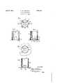
- Figure l is a top plan of the preferred form of my improved holder
- FIG. 2 is a vertical section thereof, as on the line 2 2 of Fig. 1, showing the manner in which the terminals are attached to the shell;
- Fig. 3 is a similar'section on the line 3-3 of Fig. 1 showing independent means for holding the shell to a base board or the like;
- Fig. l is a top plan of a modification of my invention which avoids the use of independent shelLholding means and is appropriate to socallexfpanel wiring;
- Fig. 5 is a vertical section ot' the device of Fig. 4 on the line 5 ⁇ 5 thereof. Referring to Figs.
- the shell 10 in my practice 1s a section of Bakelite tubing having an inside diameter sufficient to receive, for easy interitting movement, the base ortion of the well-known vacuum tube used in radio work.
- the cylindrical bases of such tubes are provided at one side with an outstanding pin :For positioning the tube in the holder. In some sockets this pin travels in a bayonet slot in the shell when applying or removing the tube.
- the shell is provided with a longitudinal slot 11 for the laterally-extending pin of the tube base whereby the tube may be inserted in the socket by simply moving it longitudinally. With the locating pin in this slot the four contact terminals of the tube are so directed as to make contact with the proper terminals of the socket respectively.
- the shell 10 carries four contact members formed of thin and springy sheet metal such as German silver or brass.
- Each of these contact members has a body part somewhat U- shaped having a seat portion 12, a pair of side members 13, the side members carrying a pair of oppositely-disposed contact ends 14 facing each other and close together, each of these contact ends being provided with a flaring top extension 15 to provide easy entrance between them o the terminals or pins extending from the base of the tubes, there being also bottom llaring extensions 16 adapted to provide easy withdrawal of the tube terminal pins in instances where they may be headed over or mushroomed by use in other types of device.
- the seat portion 12 has a normally upwardly directed leaf-like extension 17 which is bent to pass through a narrow slot-like hole or aperture punched or otherwise formed in the shell 10, and is then bent back upon the shell at 17a to crimp and fasten the contact member securely by an interlocking and clamping action upon the shell.
- the seat portion 12 has also a leaf-like downwardly directed extension 18 of suiicient length to permit it towbe bent around the lower end of the shell as additional means' for holding the contact member in place. This extension 18, after being crimped against the shell, is bent outwardly so as to form a wiring end or terminal 19.
- brackets 20 which may be of the same material as that of the contact members. These brackets 20 have their upper ends 20a extending through narrow slot-like holes -in the lower portion of the shell and are then bent over so as to engage and firmly grip the shell.
- the bottom extensions 2Gb are provided with small holes for screws with which to secure the device as a whole upon a base. It is to be noted that the brackets 20 require no screws or rivets to hold them upon the shell.
- the structure just described is particularly adapted for the above-board type of wiring.
- Another type of wiring has recently come into vogue knows as subpanel wiring.
- a horlzontal base or subpanel is provided upon which all the desired apparatus is mounted and the wiring is done below the panel so that the appearance of the completed set is .greatly improved and n Y many instances the connecting wires may be shorter and more direct.
- the construction shown in Figs. 4 and 5 is particularly adapted for such subpanel wiring. The only difierences between the construction shown in Figs.
- brackets 20 are omitted and the wiring terminals 22, corresponding in original shape to the terminals 19, are passed through holes in the base and are then bent over so as to grip the base and thus hold the shell securely.
- These extensions 22 may be bent away from the base in part for easy soldering operations and may then be bent back to lie upon the base if desired.
- the unitary and integral connection members serve to hold themselves upon the shell, to mount the shell upon the panel and to form the wiring terminals.
- a socket for a vacuum tube comprising a shell, a panel for supporting said shell, a thin sheet metal contact member mounted on said shell, said contact member having a substantially Ushaped contact portion and an extension directed through an opening in the shell and crimped against it, and having another extension passing through an opening in said panel and crimped against it to secure said shell to said panel.
- a socket for a vacuum tube comprising a shell, a panel for supporting said shell, a thin sheet metal contact member mounted on said shell, said contact member having a substantially U-shaped contact portion and an extension directed through an opening in the shell and crimped against it, and having another extension passing through an opening in said panel and crimped against it to secure said shell to said panel, one of said extensions forming a wiring terminal integral with said member.
- a socket for a vacuum tube comprising a shell, a base for sup orting said shell, and a spring contact mem n rphaving means for engaging a termi-nal of the vacuum tube and having integral means constituting the sole means for fastening said shell to said base.
- a socket for a vacuum tube comprising a shell, a base for supporting said shell, and a spring contact member for engaging a terminal of the vacuum tube mounted on said shell, said contact member having integral means constituting the sole means for fastening said shell to said base, an extension of said fastening means forming a wiring terminal integral with said contact member.
- a contact member for a vacuum tube socket having a shell and a base, said contact member including opposed leaves of thin and springy sheet metal having contact ends adapted to enga e substantially telescopically a terminal o a vacuum tube, said Contact member having extensions adapted to constitute the sole means for fastening said member to such shell and said shell to such base.
- a contact member formed of thin and fiexible sheet metal andv comprising a'substantially U-shaped body which includes arms normally horizontally disposed and the free ends of which are formed to receive frictionally between them, a pin-like terminal directed normally downward and extending transversely to the longitudinal direction of the body, the body having elongated surfaces spaced substantially apart and adapted to seat firmly upon a support at places similarly spaced apart, the body having integral leaf-like extensions associated with said base surfaces respectively and adapted to be bent over on the side of the support opposite to that on which the body is seated.
Landscapes
- Multi-Conductor Connections (AREA)
Description
April 5, 1932. w. w. ROBINSON VACUUM TUBE HOLDER Filed Feb. 12. 1926 1 W w M Patented Apr. 5, 1932 UNITED STATES PATENT OFFICE WALTER W. ROBINSGN, F IBELOIT, WISCONSIN, ASSIGNOB 0F ONE-HALF TO BENJAMIN F. LYONS, 0F CHICAGO, ILLNOIS VACUUM TUBE HOLDER Application led February 12, 1926. Serial No. 87,756.
These improvements relate to holders ordinarily termed sockets for vacuum tube devices. Such tubes contain a plurality of electrodes within a glass enclosure and terminals projecting from the cylindrical base in the .t'orm of pins extending in parallel arrangement. l
An object of the invention is to provide a unitary Contact member for engaging the projecting pins on the bottoni of the tube and which may be mounted upon the main portion ot the holder, and, as a detail or specific improvement, without the use of rivets or screws.
Another object is to provide advantageous forms of terminal connections in such a device and suitable for the usual type of wiring or 'for so-called subpanel wiring.
Another object is to provide a unitary con. tact member and a wiring projection'. An-
other object is to provide a wiring terminal for a device of this kind which may be used "tor attaching the shell of the holder or socket firmly to the base. It is also an object to accomplish these results by a simple, relatively cheap, strong and durable construction.
@ther objects and advantages will appear hereinafter.
ln the drawings, Figure l is a top plan of the preferred form of my improved holder;
3G Fig. 2 is a vertical section thereof, as on the line 2 2 of Fig. 1, showing the manner in which the terminals are attached to the shell; Fig. 3 is a similar'section on the line 3-3 of Fig. 1 showing independent means for holding the shell to a base board or the like; Fig. l is a top plan of a modification of my invention which avoids the use of independent shelLholding means and is appropriate to socallexfpanel wiring; Fig. 5 is a vertical section ot' the device of Fig. 4 on the line 5`5 thereof. Referring to Figs. l to 3 inclusive, the shell 10 in my practice 1s a section of Bakelite tubing having an inside diameter sufficient to receive, for easy interitting movement, the base ortion of the well-known vacuum tube used in radio work. The cylindrical bases of such tubes are provided at one side with an outstanding pin :For positioning the tube in the holder. In some sockets this pin travels in a bayonet slot in the shell when applying or removing the tube. In these improvements the shell is provided with a longitudinal slot 11 for the laterally-extending pin of the tube base whereby the tube may be inserted in the socket by simply moving it longitudinally. With the locating pin in this slot the four contact terminals of the tube are so directed as to make contact with the proper terminals of the socket respectively.
The shell 10 carries four contact members formed of thin and springy sheet metal such as German silver or brass. Each of these contact members has a body part somewhat U- shaped having a seat portion 12, a pair of side members 13, the side members carrying a pair of oppositely-disposed contact ends 14 facing each other and close together, each of these contact ends being provided with a flaring top extension 15 to provide easy entrance between them o the terminals or pins extending from the base of the tubes, there being also bottom llaring extensions 16 adapted to provide easy withdrawal of the tube terminal pins in instances where they may be headed over or mushroomed by use in other types of device.
The seat portion 12 has a normally upwardly directed leaf-like extension 17 which is bent to pass through a narrow slot-like hole or aperture punched or otherwise formed in the shell 10, and is then bent back upon the shell at 17a to crimp and fasten the contact member securely by an interlocking and clamping action upon the shell. The seat portion 12 has also a leaf-like downwardly directed extension 18 of suiicient length to permit it towbe bent around the lower end of the shell as additional means' for holding the contact member in place. This extension 18, after being crimped against the shell, is bent outwardly so as to form a wiring end or terminal 19.
According to this construction the use of rivets or the like for holding the contact members is avoided, and no separate parts are 9 required for the wiring connections. The unitary construction provides against electrical loss through poor connectionsand the construction is cheap, durable and highly satisfactory in use. l
An important advantage is in the unusually advantageous results provided by the substantially large area of the terminal of the tube contacted by the contact member. 'lhat is to say, instead of an electr-ical connection made with the pins of the tube through flat springs pressing against the small usually rounded surface at the bottom of the pins projecting from the tube base, electrical connection is here made on comparatively long lines or areas at the sides of the respective 1ns. p Means for holding the shell 10 upon a base are shown as two substantially- L-sha-ped brackets 20 which may be of the same material as that of the contact members. These brackets 20 have their upper ends 20a extending through narrow slot-like holes -in the lower portion of the shell and are then bent over so as to engage and firmly grip the shell. The bottom extensions 2Gb are provided with small holes for screws with which to secure the device as a whole upon a base. It is to be noted that the brackets 20 require no screws or rivets to hold them upon the shell.
The structure just described is particularly adapted for the above-board type of wiring. Another type of wiring has recently come into vogue knows as subpanel wiring. For this type of wiring a horlzontal base or subpanel is provided upon which all the desired apparatus is mounted and the wiring is done below the panel so that the appearance of the completed set is .greatly improved and n Y many instances the connecting wires may be shorter and more direct. The construction shown in Figs. 4 and 5 is particularly adapted for such subpanel wiring. The only difierences between the construction shown in Figs. 4 and 5 and that of the preceding figures are that the brackets 20 are omitted and the wiring terminals 22, corresponding in original shape to the terminals 19, are passed through holes in the base and are then bent over so as to grip the base and thus hold the shell securely. These extensions 22 may be bent away from the base in part for easy soldering operations and may then be bent back to lie upon the base if desired.
In this type of construction also the unitary and integral connection members serve to hold themselves upon the shell, to mount the shell upon the panel and to form the wiring terminals.
I contemplate as being included in these improvements such changes, modifications and departures from what is herein specili cally set forth as fall within the scope of the appended claims.
l. A socket for a vacuum tube comprising a shell, a panel for supporting said shell, a thin sheet metal contact member mounted on said shell, said contact member having a substantially Ushaped contact portion and an extension directed through an opening in the shell and crimped against it, and having another extension passing through an opening in said panel and crimped against it to secure said shell to said panel.
2. A socket for a vacuum tube comprising a shell, a panel for supporting said shell, a thin sheet metal contact member mounted on said shell, said contact member having a substantially U-shaped contact portion and an extension directed through an opening in the shell and crimped against it, and having another extension passing through an opening in said panel and crimped against it to secure said shell to said panel, one of said extensions forming a wiring terminal integral with said member.
3. A socket for a vacuum tube comprising a shell, a base for sup orting said shell, and a spring contact mem n rphaving means for engaging a termi-nal of the vacuum tube and having integral means constituting the sole means for fastening said shell to said base.
4. A socket for a vacuum tube comprising a shell, a base for supporting said shell, and a spring contact member for engaging a terminal of the vacuum tube mounted on said shell, said contact member having integral means constituting the sole means for fastening said shell to said base, an extension of said fastening means forming a wiring terminal integral with said contact member. f
5..,A contact member for a vacuum tube socket having a shell and a base, said contact member including opposed leaves of thin and springy sheet metal having contact ends adapted to enga e substantially telescopically a terminal o a vacuum tube, said Contact member having extensions adapted to constitute the sole means for fastening said member to such shell and said shell to such base.
6. A contact member formed of thin and fiexible sheet metal andv comprising a'substantially U-shaped body which includes arms normally horizontally disposed and the free ends of which are formed to receive frictionally between them, a pin-like terminal directed normally downward and extending transversely to the longitudinal direction of the body, the body having elongated surfaces spaced substantially apart and adapted to seat firmly upon a support at places similarly spaced apart, the body having integral leaf-like extensions associated with said base surfaces respectively and adapted to be bent over on the side of the support opposite to that on which the body is seated.
WALTER W. ROBINSON.
Priority Applications (1)
| Application Number | Priority Date | Filing Date | Title |
|---|---|---|---|
| US87756A US1852334A (en) | 1926-02-12 | 1926-02-12 | Vacuum tube holder |
Applications Claiming Priority (1)
| Application Number | Priority Date | Filing Date | Title |
|---|---|---|---|
| US87756A US1852334A (en) | 1926-02-12 | 1926-02-12 | Vacuum tube holder |
Publications (1)
| Publication Number | Publication Date |
|---|---|
| US1852334A true US1852334A (en) | 1932-04-05 |
Family
ID=22207061
Family Applications (1)
| Application Number | Title | Priority Date | Filing Date |
|---|---|---|---|
| US87756A Expired - Lifetime US1852334A (en) | 1926-02-12 | 1926-02-12 | Vacuum tube holder |
Country Status (1)
| Country | Link |
|---|---|
| US (1) | US1852334A (en) |
Cited By (1)
| Publication number | Priority date | Publication date | Assignee | Title |
|---|---|---|---|---|
| US3195096A (en) * | 1962-04-30 | 1965-07-13 | Eitel Mccullough Inc | Socket for electron tubes |
-
1926
- 1926-02-12 US US87756A patent/US1852334A/en not_active Expired - Lifetime
Cited By (1)
| Publication number | Priority date | Publication date | Assignee | Title |
|---|---|---|---|---|
| US3195096A (en) * | 1962-04-30 | 1965-07-13 | Eitel Mccullough Inc | Socket for electron tubes |
Similar Documents
| Publication | Publication Date | Title |
|---|---|---|
| US2229989A (en) | Clip member and clip member installations | |
| US1635256A (en) | Terminal connecter | |
| US4278316A (en) | Rejector fuse clip assembly | |
| GB1170199A (en) | Electrical Connector. | |
| US1747628A (en) | Safety-pin holder | |
| US1724729A (en) | Electrical contact clip | |
| US2747169A (en) | Contact for printed circuits | |
| US1852334A (en) | Vacuum tube holder | |
| US2017940A (en) | Socket for vacuum tubes and the like | |
| US1969991A (en) | Electrical contact device | |
| US2259739A (en) | Vacuum tube socket | |
| US1719288A (en) | Radio tube socket | |
| US3541381A (en) | Plug-in lighting assembly | |
| US4171856A (en) | Substrate recessed receptacle | |
| US1704515A (en) | Radio tube holder | |
| US2454760A (en) | Electrical connector | |
| US3118717A (en) | Elastic lamps, constructions, mountings and receptacles | |
| US2036384A (en) | Vacuum tube socket | |
| US1980214A (en) | Mounting for electric devices | |
| US2706804A (en) | Wire connection binding clip | |
| US2203099A (en) | Art of bonding metal to insulation | |
| US2211739A (en) | Lamp socket and lamp socket installations | |
| US1671226A (en) | Lamp socket | |
| US2149084A (en) | Electric receptacle | |
| US1641530A (en) | Radiotube socket |