US1852311A - Multiple glass cutting machine - Google Patents
Multiple glass cutting machine Download PDFInfo
- Publication number
- US1852311A US1852311A US352211A US35221129A US1852311A US 1852311 A US1852311 A US 1852311A US 352211 A US352211 A US 352211A US 35221129 A US35221129 A US 35221129A US 1852311 A US1852311 A US 1852311A
- Authority
- US
- United States
- Prior art keywords
- cutter
- cutting tool
- glass
- body portion
- cutting
- Prior art date
- Legal status (The legal status is an assumption and is not a legal conclusion. Google has not performed a legal analysis and makes no representation as to the accuracy of the status listed.)
- Expired - Lifetime
Links
- 239000011521 glass Substances 0.000 title description 15
- 229910003460 diamond Inorganic materials 0.000 description 10
- 239000010432 diamond Substances 0.000 description 10
- 239000005357 flat glass Substances 0.000 description 6
- 238000010276 construction Methods 0.000 description 1
- 238000000034 method Methods 0.000 description 1
- 238000012986 modification Methods 0.000 description 1
- 230000004048 modification Effects 0.000 description 1
- 239000011435 rock Substances 0.000 description 1
Images
Classifications
-
- C—CHEMISTRY; METALLURGY
- C03—GLASS; MINERAL OR SLAG WOOL
- C03B—MANUFACTURE, SHAPING, OR SUPPLEMENTARY PROCESSES
- C03B33/00—Severing cooled glass
- C03B33/10—Glass-cutting tools, e.g. scoring tools
-
- C—CHEMISTRY; METALLURGY
- C03—GLASS; MINERAL OR SLAG WOOL
- C03B—MANUFACTURE, SHAPING, OR SUPPLEMENTARY PROCESSES
- C03B33/00—Severing cooled glass
- C03B33/02—Cutting or splitting sheet glass or ribbons; Apparatus or machines therefor
- C03B33/023—Cutting or splitting sheet glass or ribbons; Apparatus or machines therefor the sheet or ribbon being in a horizontal position
- C03B33/027—Scoring tool holders; Driving mechanisms therefor
Definitions
- Another object of our invention is to pro vide means for permitting the diamond cutting tool to rise and fall as it passes over irregularities in the surface of a sheet of glass and at the same time always keeping the cutting edge of the diamond in its operative position.
- our invention consists of movably mounting the cutting tool on the cutter by means of two pivotally parallel levers in such a manner that the cutting tool as it moves always remains in parallel relation with its former position.
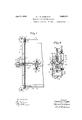
- Figure 1 of which is a plan view of a multiple glass outing machine constructed in accordance with our invention.
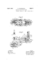
- FIGs 2, 3 and 4 are views, in plan, side and end elevation, respectively, of the cutters illustrated in Figure 1 of the drawings.
- a table 1 having a wooden top 2
- the carriage 5 is provided with a plurality of rails 3 (only one illustrated) on which is movably mounted a carriage 4.
- the carriage d is provided with a plurality of rollers 5a which engage the rails 3.
- a plurality of cutters 5 (only one illustrated) are slidably mounted upon the carriage
- the movement of thecarriage 4 is governed by a plurality of chains 6 (only one illustrated) which are secured to said carriage and are mounted upon a plura ity of sprocket wheels 7 and 8.
- the pair of sprocket wheels 7 are rigidly secured to a shaft 9 so the wheels 7 will rotate at the same speed.
- a plurality of resiliently mounted pins 39 are employed for stopping the car- Serial No. 352,211.
- bracket 63 is so provided with a horizontal oif set 65 that ample clearance is provided between the bracket 63 and the left side of the table 1 to permit the ragged edge of glass to project over the left of the table 1.
- the rod 61 is graduated in feet and inches, so that the cutter 5 may be postioned thereon as desired by the operator.
- the rod 62 is provided with a plurality of teeth (8 to the inch) to definitely position the cutters 5 in a manner hereinafter more fully described.
- Each of the cutters 5 comprises two body members 74 and 75, which form a body portion and are adapted to fit around the rods 61 and 62 of the carriage 4 upon which the cuttor 5 is slidably mounted and they are securely fastened one to another by a plurality of bolts 75a.
- the lower body portion 74 of the cutter 5 is provided with two downwardly projecting bars 7 6, which are adapted to support a plurality of levers 77 and 78 which are pivotally mounted thereon.
- the levers 77 and 78 are pivotally connected to a holding device 79 for a cutting tool 80, a description of which will be hereinafter more fully given.
- the lever 77 is provided with a horizontal flange 81 at the opposite end from the cutting tool 80.
- the upper portion 75 of the cutter 5 is provided with a horizontal flange or projection 82, which is reinforced by a V shaped vertical projection or brace 83.
- a handle 84 forms part of the flange 82 of the cutter 5.
- a resilient member or spring 90 is fastened to a threaded rod 85 upon which is mounted a sleeve 86 and an adjusting nut 87
- the sleeve 85 may be positioned in any one of a plurality of sockets 88 in the horizontal flangd 82.
- the other end of the spring is fastened to a relatively small bar 89 which is secured to the lever 77 by means of bolts 91. This method of mounting the spring 90 permits the tension therein to be adjusted by moving the sleeve 86 to various sockets 88 in the flange 82.
- the body portion 74 of the cutter 5 is provided with a lug 92 in which is positioned a screw-93 for adjustably limiting'the upward movement of the lever 77.
- Aplate 94 which is slidably mounted in the horizontal flange 81 of the lever 77, is employed for locking the cutting tool in 'an inoperative position.
- the plate 94 may be actuated by the handle 95 which is secured to one end thereof.
- the plate 94 occupies the position, illustrated in Fig. 3 of the drawings, then the .cutting tool. 80 is raised fromthesurface of the glass 111.
- an adjustable bolt 96 engages the screw 93..an'd permits the cutting 13001180 to engage the sheet of glass 111.
- the cutter. 5 is provided with .a plurality .ofplungers 102 and 103 for engaging the teeth of the horizontal bar or rock member '62 of "the carriage 4.
- the plungers 102 and 103 are mounted in threaded sleeves 104 and eeach is providedwith a-handle 105.
- a pin 106 is providedineach of theplungers 102 and i103 foralocking them in an inoperative posi- "tion when desired. This locking is effected byproviding .a slot in eachof the sleeves 104 in-.which'the pin 106 lies, when the pin 106 :occupies its looking or operative position.
- the plunger @102and 103 are spaced apart a distance of 1%.
- the plunger'1'03 is employed to;lock1the cutter 5 inposition.
- the other aplunger 1102 is employed for setting'the cutter-51in: any one ofthe sixteenth positions on the scale of the carriagei4.
- The-cuttingtool 80 is-provided with a diamond 1.09 at-its lower edgeforcutting a sheet ofaglass'lll (see Fig. 3). 'The cutting tool 80 is-slidably positioned É small shaft 112 by means of a screw 110.
- the shaft 112 is imounted in abent-plate 113'by means of a screw'bolt 114 in the sametmanner as illustrated in the Patent No. 1,301,950, granted to Klages.
- the :plate 113 is mounted in a rigidmember 118 :bymeans of a threaded bolt 119.
- the rigid member 118 is provided with an arcuate projection, (not illustrated) which is adapted to fit in a corresponding groove (not illustrated) in the bent plate 113 inthe same manner as illustrated in the patent to Klages No. 1,301,950.
- This groove arrangement permits the bent plate 113 to be actuated thereby adjusting the angle of inclination of the cutting tool 80 without changing the distance of the diamond .109 from. its position with respect to the cutter 5.
- the rigid member 118 is provided with two relatively deep grooves 121 and 122 in which corresponding projections 123 and 124 of a rigid member 125 are slidably mounted. This arrangement permits of horizontal adj ust- .ment of the relative positions of the rigid members 118 and the diamond 109 with the rigid member 125.
- the rigid member 125 is provided with two outwardly projecting -arms 12.6,which. are adapted to slidingly fit upon a bolt. 127, which. is mounted upon a horizontal projection 128 of the rigid'member 79.
- the rigid member 118 is provided With two'- flange projections 129 between which the bumping'block 99 is pivotallymounted.
- the cutters 5 are set in predetermined po sition upon the rods 61 and 62 of the carriage 4. Each of the cutters 5 is positioned to the nearest eighth of an. inch by means of the plunger103.
- the diamond 109 in the cutting tool 80 has already been adjusted to a predetermined position with relation to the reference mark on the cutter 5. In case it is desired to render one of the cutters 5 inopera- .tive,-the diamond 109 is locked in its inopera tive position by means of the plate 94, being actuated inwardly to the position" illustrated by. Figure 3 of the drawings.
- the carriage 4 is then actuated tothe rear of the table 1 and a sheet of glass is then placed upon the Wooden top 2 thereof.
- a cutter for cutting sheet glass comprising a body portion having a bar, a cutting tool, a holding device for said cutting tool, a lever for pivotally mounting said holding device on said body portion, and means comprising a second lever for mechanically connecting said holding device to said bar to permit angular movement of said first lever and maintain said cutting tool in predetermined angular relation with said glass.
- a cutter for cutting sheet glass comprising a body portion, a holding device, a cutting tool mounted on said holding device, and two pivotally mounted levers for movably connecting said holding device to said body portion, said levers being vertically positioned one above the other upon said body portion and adapted to turn in the same plane, to maintain said cutting tool parallel to itself as it is moved to and from the glass.
- a cutter for cutting sheet glass comprising a body portion, two levers pivotally mounted upon said body portion, and adapted to turn in the same plane, a cutting tool and means comprising a rigid member for pivotally connecting said levers to said cutting tool, said means cooperating with said levers to maintain said cutting tool always in predetermining angular relation to the glass.
- a cutter for cutting sheet glass comprising a body portion, a plurality of levers, a cutter holding device having a diamond mounted therein, a plurality of bolts for pivotally mounting said holding device on said levers, all of said bolts being so positioned one to another as to maintain said levers, holding device and said body portion in parallelogram relation thereby maintaining said diamond in fixed angular relation to said glass, as said tool rises and falls on said glass.
- a cutter for cutting sheet glass comprising a body portion, having a projecting bar, a pair of rigid members pivotally secured to said bar, a third rigid member for holding a cutting tool and pivotally secured to said pair of rigid members, said third rigid member and said bar being maintained in parallel relation by said pair of rigid members to keep the cutting tool parallel to itself as it moves to and from the glass.
- a cutter for cutting sheet glass comprising a body portion having a projecting bar, a lever provided with a handle pivotally mounted on said bar, resilient means tending to turn said lever in one direction, adjustable means for limiting angular movement of said lever in the same direction, a second lever CHESTER F. KLAGES. NORMAN n. KLAGES.
Landscapes
- Chemical & Material Sciences (AREA)
- Engineering & Computer Science (AREA)
- Materials Engineering (AREA)
- Organic Chemistry (AREA)
- Re-Forming, After-Treatment, Cutting And Transporting Of Glass Products (AREA)
Description
April 1932- c. F. KLAGES ET AL 1,852,311
MULTIPLE GLASS CUTTING MACHINE Original Filed Aug. 24. 1925 2 Sheets-Sheet l INVENTOR aim, Norma/7H /f/a es 9 B Y J@.' $60100 April 5, 1932. 1
C. F. KLAGES ET AL MULTIPLE GLASS CUTTING MACHINE Original Filed Aug. 24. 1925 2 Sheets-Sheet 2 84 83 l}! :I 105 .1 f] n' 104 90 93 69 91 95 INVENTOR Mesfer lf/ayes Norma/7 H K/ayes Patented Apr. 5, 1932 UNITED STATES PATENT OFFICE CHESTER 1?. KLAG-ES AND NORMAN H. KLAGES, F PITTSBURGH, PENNSYLVANIA,
ASSIG-NORS TO G. W. KLAGES & SON, INCORPORATED, 013 PITTSBURGH, PENNSYL- VAN IA, A CORPORATION 03? PENNSYLVANIA.
MULTIPLE GLASS CUTTING MACHINE Original application filed August 24, 1925, Serial N'o. 52,093. Divided and this application filed April 3,
in the slo no of the diamond holder.
Another object of our invention is to pro vide means for permitting the diamond cutting tool to rise and fall as it passes over irregularities in the surface of a sheet of glass and at the same time always keeping the cutting edge of the diamond in its operative position.
Briefly speaking, our invention consists of movably mounting the cutting tool on the cutter by means of two pivotally parallel levers in such a manner that the cutting tool as it moves always remains in parallel relation with its former position.
For a better understanding of my inven tion, reference may be made to the accompanying drawings.
Figure 1 of which is a plan view of a multiple glass outing machine constructed in accordance with our invention.
Figures 2, 3 and 4 are views, in plan, side and end elevation, respectively, of the cutters illustrated in Figure 1 of the drawings.
Referring particularly to Fig. 1 of the drawings, a table 1, having a wooden top 2,
5 is provided with a plurality of rails 3 (only one illustrated) on which is movably mounted a carriage 4. The carriage d is provided with a plurality of rollers 5a which engage the rails 3. A plurality of cutters 5 (only one illustrated) are slidably mounted upon the carriage The movement of thecarriage 4 is governed by a plurality of chains 6 (only one illustrated) which are secured to said carriage and are mounted upon a plura ity of sprocket wheels 7 and 8. The pair of sprocket wheels 7 are rigidly secured to a shaft 9 so the wheels 7 will rotate at the same speed. A plurality of resiliently mounted pins 39 are employed for stopping the car- Serial No. 352,211.
Referring again to carriage 4, it comprises two horizontal rods or bars 61 and 62 which are mounted in a plurality of brackets 63, only one of which is illustrated in this divisional application. The bracket 63 is so provided with a horizontal oif set 65 that ample clearance is provided between the bracket 63 and the left side of the table 1 to permit the ragged edge of glass to project over the left of the table 1.
The rod 61 is graduated in feet and inches, so that the cutter 5 may be postioned thereon as desired by the operator. The rod 62 is provided with a plurality of teeth (8 to the inch) to definitely position the cutters 5 in a manner hereinafter more fully described.
Each of the cutters 5 comprises two body members 74 and 75, which form a body portion and are adapted to fit around the rods 61 and 62 of the carriage 4 upon which the cuttor 5 is slidably mounted and they are securely fastened one to another by a plurality of bolts 75a.
The lower body portion 74 of the cutter 5 is provided with two downwardly projecting bars 7 6, which are adapted to support a plurality of levers 77 and 78 which are pivotally mounted thereon. The levers 77 and 78 are pivotally connected to a holding device 79 for a cutting tool 80, a description of which will be hereinafter more fully given.
The lever 77 is provided with a horizontal flange 81 at the opposite end from the cutting tool 80. The upper portion 75 of the cutter 5 is provided with a horizontal flange or projection 82, which is reinforced by a V shaped vertical projection or brace 83. A handle 84 forms part of the flange 82 of the cutter 5.
A resilient member or spring 90 is fastened to a threaded rod 85 upon which is mounted a sleeve 86 and an adjusting nut 87 The sleeve 85 may be positioned in any one of a plurality of sockets 88 in the horizontal flangd 82. The other end of the spring is fastened to a relatively small bar 89 which is secured to the lever 77 by means of bolts 91. This method of mounting the spring 90 permits the tension therein to be adjusted by moving the sleeve 86 to various sockets 88 in the flange 82.
The body portion 74 of the cutter 5 is provided with a lug 92 in which is positioned a screw-93 for adjustably limiting'the upward movement of the lever 77. Aplate 94, which is slidably mounted in the horizontal flange 81 of the lever 77, is employed for locking the cutting tool in 'an inoperative position. The plate 94 may be actuated by the handle 95 which is secured to one end thereof.
lVhen the plate 94 occupies the position, illustrated in Fig. 3 of the drawings, then the .cutting tool. 80 is raised fromthesurface of the glass 111. When the plate 94isdrawn outwardly then an adjustable bolt 96 engages the screw 93..an'd permits the cutting 13001180 to engage the sheet of glass 111.
.Anoil cup .97 is'securelyjmounted on the lower body'portion- 74 ofthe cutter 5. A pipe 1 98 eXtends from the oilcup 97 to a pivotally :mountedbumper 99 which is provided'with :.an oilzpad 101 on its surface.
The cutter. 5 is provided with .a plurality . ofplungers 102 and 103 for engaging the teeth of the horizontal bar or rock member '62 of "the carriage 4. The plungers 102 and 103 are mounted in threaded sleeves 104 and eeach is providedwith a-handle 105. A pin 106 is providedineach of theplungers 102 and i103 foralocking them in an inoperative posi- "tion when desired. This locking is effected byproviding .a slot in eachof the sleeves 104 in-.which'the pin 106 lies, when the pin 106 :occupies its looking or operative position.
.An ofl'set is providedin each of .the sleeves 1041in "which the corresponding pin 106ilies when the. plunger 102 or103 occupies itswunlocked or inoperative position. The plunger @102and 103 are spaced apart a distance of 1%. When it is desired to set the cutter 51 at some one of the eighth divisions on the carriage 4, the plunger'1'03 isemployed to;lock1the cutter 5 inposition. The other aplunger 1102 is employed for setting'the cutter-51in: any one ofthe sixteenth positions on the scale of the carriagei4.
The-cuttingtool 80 is-provided with a diamond 1.09 at-its lower edgeforcutting a sheet ofaglass'lll (see Fig. 3). 'The cutting tool 80 is-slidably positioned insa small shaft 112 by means of a screw 110. The shaft 112 is imounted in abent-plate 113'by means of a screw'bolt 114 in the sametmanner as illustrated in the Patent No. 1,301,950, granted to Klages. An arcuate= shaped groove (not i1- lustrated) is provided inthe bent plate 113 and :a corresponding arcuate projection 116 :is providedinthe-flared end of the shaft 112.
:Theeifect of the projection'116 of the shaft '112 slidablyfitting in the bent plate 113'is to maintain-thediamon'd 1090f the cuttingtool '80 st-ationary, as the-upper portion ofthe tool 80'is actuated through the arc of a circle. The :plate 113 is mounted in a rigidmember 118 :bymeans of a threaded bolt 119. The rigid member 118 is provided with an arcuate projection, (not illustrated) which is adapted to fit in a corresponding groove (not illustrated) in the bent plate 113 inthe same manner as illustrated in the patent to Klages No. 1,301,950.
This groove arrangement permits the bent plate 113 to be actuated thereby adjusting the angle of inclination of the cutting tool 80 without changing the distance of the diamond .109 from. its position with respect to the cutter 5.
The rigid member 118 is provided with two relatively deep grooves 121 and 122 in which corresponding projections 123 and 124 of a rigid member 125 are slidably mounted. This arrangement permits of horizontal adj ust- .ment of the relative positions of the rigid members 118 and the diamond 109 with the rigid member 125. The rigid member 125 is provided with two outwardly projecting -arms 12.6,which. are adapted to slidingly fit upon a bolt. 127, which. is mounted upon a horizontal projection 128 of the rigid'member 79. The rigid member 118 is provided With two'- flange projections 129 between which the bumping'block 99 is pivotallymounted.
The operation of our invention is as follows:
The cutters 5 are set in predetermined po sition upon the rods 61 and 62 of the carriage 4. Each of the cutters 5 is positioned to the nearest eighth of an. inch by means of the plunger103. The diamond 109 in the cutting tool 80 has already been adjusted to a predetermined position with relation to the reference mark on the cutter 5. In case it is desired to render one of the cutters 5 inopera- .tive,-the diamond 109 is locked in its inopera tive position by means of the plate 94, being actuated inwardly to the position" illustrated by. Figure 3 of the drawings.
The carriage 4 is then actuated tothe rear of the table 1 anda sheet of glass is then placed upon the Wooden top 2 thereof.
The carriage 4 is then drawn at a moderate speed toward the operator. VVhen' the bumping block 99 comes in contact with the edge of the sheet of glass 111, the block 99 is forced upwardly thereby raising the cutting tool 80- which holds the diamond-109. This upward movement of the cutting tool 80 does not change the angle ofinclination of thecutting tool 80 with the sheet of, glass 111. The rea- While we have shown our invention in its preferred form, it is apparent that minor modifications maybe made in the construction of the table Without departing from the spirit of our invention. Ne desire, therefore, to be limited only by the scope of the appended claims.
We claim:
1. A cutter for cutting sheet glass comprising a body portion having a bar, a cutting tool, a holding device for said cutting tool, a lever for pivotally mounting said holding device on said body portion, and means comprising a second lever for mechanically connecting said holding device to said bar to permit angular movement of said first lever and maintain said cutting tool in predetermined angular relation with said glass. it
2. A cutter for cutting sheet glass comprising a body portion, a holding device, a cutting tool mounted on said holding device, and two pivotally mounted levers for movably connecting said holding device to said body portion, said levers being vertically positioned one above the other upon said body portion and adapted to turn in the same plane, to maintain said cutting tool parallel to itself as it is moved to and from the glass.
A cutter for cutting sheet glass comprising a body portion, two levers pivotally mounted upon said body portion, and adapted to turn in the same plane, a cutting tool and means comprising a rigid member for pivotally connecting said levers to said cutting tool, said means cooperating with said levers to maintain said cutting tool always in predetermining angular relation to the glass.
i. A cutter for cutting sheet glass comprising a body portion, a plurality of levers, a cutter holding device having a diamond mounted therein, a plurality of bolts for pivotally mounting said holding device on said levers, all of said bolts being so positioned one to another as to maintain said levers, holding device and said body portion in parallelogram relation thereby maintaining said diamond in fixed angular relation to said glass, as said tool rises and falls on said glass.
5. A cutter for cutting sheet glass comprising a body portion, having a projecting bar, a pair of rigid members pivotally secured to said bar, a third rigid member for holding a cutting tool and pivotally secured to said pair of rigid members, said third rigid member and said bar being maintained in parallel relation by said pair of rigid members to keep the cutting tool parallel to itself as it moves to and from the glass.
6. A cutter for cutting sheet glass comprising a body portion having a projecting bar, a lever provided with a handle pivotally mounted on said bar, resilient means tending to turn said lever in one direction, adjustable means for limiting angular movement of said lever in the same direction, a second lever CHESTER F. KLAGES. NORMAN n. KLAGES.
Priority Applications (1)
| Application Number | Priority Date | Filing Date | Title |
|---|---|---|---|
| US352211A US1852311A (en) | 1925-08-24 | 1929-04-03 | Multiple glass cutting machine |
Applications Claiming Priority (2)
| Application Number | Priority Date | Filing Date | Title |
|---|---|---|---|
| US5209325A | 1925-08-24 | 1925-08-24 | |
| US352211A US1852311A (en) | 1925-08-24 | 1929-04-03 | Multiple glass cutting machine |
Publications (1)
| Publication Number | Publication Date |
|---|---|
| US1852311A true US1852311A (en) | 1932-04-05 |
Family
ID=26730167
Family Applications (1)
| Application Number | Title | Priority Date | Filing Date |
|---|---|---|---|
| US352211A Expired - Lifetime US1852311A (en) | 1925-08-24 | 1929-04-03 | Multiple glass cutting machine |
Country Status (1)
| Country | Link |
|---|---|
| US (1) | US1852311A (en) |
-
1929
- 1929-04-03 US US352211A patent/US1852311A/en not_active Expired - Lifetime
Similar Documents
| Publication | Publication Date | Title |
|---|---|---|
| US1931730A (en) | Means for setting planer heads | |
| US1802096A (en) | Planer attachment for jointers | |
| US2101343A (en) | ponton | |
| US1852311A (en) | Multiple glass cutting machine | |
| US1165248A (en) | Saw-filing machine. | |
| US1694074A (en) | Attachment for grinding machines | |
| US1907297A (en) | Multiple glass cutting machine | |
| US1852310A (en) | Multiple glass cutting machine | |
| US2151802A (en) | Grinding wheel trimming device | |
| US1998968A (en) | Cutting machine | |
| US1582396A (en) | Mitering machine | |
| US2048935A (en) | Glass cutter | |
| US1583963A (en) | Apparatus for grinding and polishing precious stones | |
| US2026042A (en) | Machine for manufacturing wood heels for shoes | |
| US935425A (en) | Butter-cutting machine. | |
| US381775A (en) | Saw sharpening machine | |
| US2090649A (en) | Indexing attachment for slotting machines | |
| US2450135A (en) | Work support arrangement for grinding and dressing machines | |
| US2091332A (en) | Glass cutting apparatus | |
| US1906279A (en) | Glass cutting machine | |
| US1427757A (en) | Stock-positioning mechanism | |
| US1677484A (en) | Grinding apparatus | |
| US2213011A (en) | Machine for cutting tile and like articles | |
| US1964261A (en) | Rail slotting machine | |
| US1621331A (en) | Lens cutter |